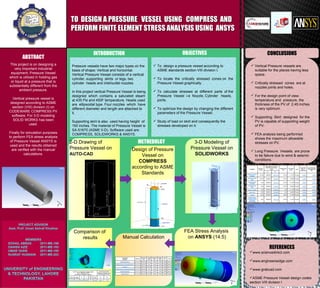
TO DESIGN A PRESSURE VESSEL USING COMPRESS ANDTO DESIGN A PRESSURE VESSEL USING COMPRESS AND
PERFORM FINITE ELEMENT STRESS ANALYSIS USING ANSYSPERFORM FINITE ELEMENT STRESS ANALYSIS USING ANSYS
ABSTRACT
CONTACT
This project is on designing a
very important industrial
equipment; Pressure Vessel
which is utilized in holding gas
or liquid at a pressure that is
substantially different from the
ambient pressure.
Vertical pressure vessel is
designed according to ASME
section (VIII) division (I) on
CODEWARE COMPRESS PV
software. For 3-D modeling
SOLID WORKS has been
used.
Finally for simulation purposes
to perform FEA stress analysis
of Pressure Vessel ANSYS is
used and the results obtained
are verified with the manual
calculations.
Pressure vessels have two major types on the
basis of shape; Vertical and horizontal.
Vertical Pressure Vessel consists of a vertical
cylinder, supporting skirts or legs, two
cylinder heads and inlet/outlet nozzles.
In this project vertical Pressure Vessel is being
designed which contains a saturated steam
at 435 Psi and 450F temperature. Heads used
are ellipsoidal type. Four nozzles which have
different diameter and length are attached to
it.
Supporting skirt is also used having height of
150 inches. The material of Pressure Vessel is
SA-51670 (ASME II-D). Software used are:
COMPRESS, SOLIDWORKS & ANSYS.
REFERENCES
www.sciencedirect.com
www.engineersedge.com
www.grabcad.com
ASME Pressure Vessel design codes
section VIII division I
2-D Drawing of
Pressure Vessel on
AUTO-CAD
Design of Pressure
Vessel on
COMPRESS
according to ASME
Standards
3-D Modeling of
Pressure Vessel on
SOLIDWORKS
Manual Calculation
Comparison of
results
FEA Stress Analysis
on ANSYS (14.5)
METHEDOLGY
INTRODUCTION
 To design a pressure vessel according to
ASME standards section VIII division I.
 To locate the critically stressed zones on the
Pressure Vessel graphically.
 To calculate stresses at different parts of the
Pressure Vessel i-e Nozzle, Cylinder heads,
joints.
 To optimize the design by changing the different
parameters of the Pressure Vessel.
 Study of load on skirt and consequently the
stresses developed on it.
OBJECTIVES CONCLUSIONS
 Vertical Pressure vessels are
suitable for the places having less
space.
 Critically stressed zones are at
nozzles joints and holes.
 For the design point of view;
temperature and pressure, the
thickness of the PV of 2.45 inches
is very optimum.
 Supporting Skirt designed for the
PV is capable of supporting weight
of PV.
 FEA analysis being performed
shows the maximum allowable
stresses on PV.
 Long Pressure Vessels are prone
to be failure due to wind & seismic
conditions.

final year project poster

  • 1.
    TO DESIGN APRESSURE VESSEL USING COMPRESS ANDTO DESIGN A PRESSURE VESSEL USING COMPRESS AND PERFORM FINITE ELEMENT STRESS ANALYSIS USING ANSYSPERFORM FINITE ELEMENT STRESS ANALYSIS USING ANSYS ABSTRACT CONTACT This project is on designing a very important industrial equipment; Pressure Vessel which is utilized in holding gas or liquid at a pressure that is substantially different from the ambient pressure. Vertical pressure vessel is designed according to ASME section (VIII) division (I) on CODEWARE COMPRESS PV software. For 3-D modeling SOLID WORKS has been used. Finally for simulation purposes to perform FEA stress analysis of Pressure Vessel ANSYS is used and the results obtained are verified with the manual calculations. Pressure vessels have two major types on the basis of shape; Vertical and horizontal. Vertical Pressure Vessel consists of a vertical cylinder, supporting skirts or legs, two cylinder heads and inlet/outlet nozzles. In this project vertical Pressure Vessel is being designed which contains a saturated steam at 435 Psi and 450F temperature. Heads used are ellipsoidal type. Four nozzles which have different diameter and length are attached to it. Supporting skirt is also used having height of 150 inches. The material of Pressure Vessel is SA-51670 (ASME II-D). Software used are: COMPRESS, SOLIDWORKS & ANSYS. REFERENCES www.sciencedirect.com www.engineersedge.com www.grabcad.com ASME Pressure Vessel design codes section VIII division I 2-D Drawing of Pressure Vessel on AUTO-CAD Design of Pressure Vessel on COMPRESS according to ASME Standards 3-D Modeling of Pressure Vessel on SOLIDWORKS Manual Calculation Comparison of results FEA Stress Analysis on ANSYS (14.5) METHEDOLGY INTRODUCTION  To design a pressure vessel according to ASME standards section VIII division I.  To locate the critically stressed zones on the Pressure Vessel graphically.  To calculate stresses at different parts of the Pressure Vessel i-e Nozzle, Cylinder heads, joints.  To optimize the design by changing the different parameters of the Pressure Vessel.  Study of load on skirt and consequently the stresses developed on it. OBJECTIVES CONCLUSIONS  Vertical Pressure vessels are suitable for the places having less space.  Critically stressed zones are at nozzles joints and holes.  For the design point of view; temperature and pressure, the thickness of the PV of 2.45 inches is very optimum.  Supporting Skirt designed for the PV is capable of supporting weight of PV.  FEA analysis being performed shows the maximum allowable stresses on PV.  Long Pressure Vessels are prone to be failure due to wind & seismic conditions.