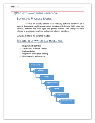
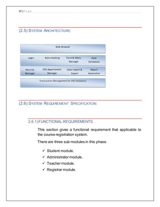
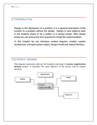
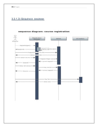
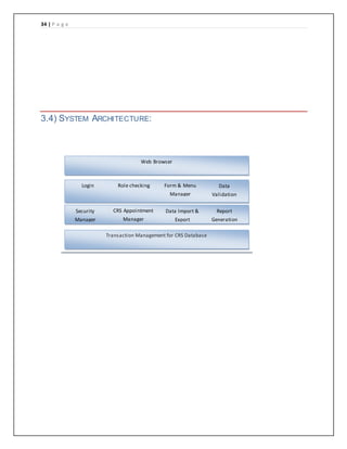
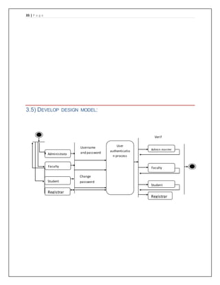
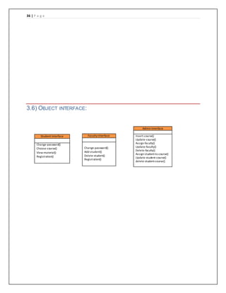
2. 1 | P a g e
ASSIGNMENT SOFTWARE ENGINEERING:
Name:
NADEEM SHAHZAD
HASSAN IQBAL
CLASS:
BS (CS) 4TH
semester
ROLL NO:
BCSM_F14_019
BCSM_F14_021
Submitted to:
SIR Obaidullah
Superior university Sialkot campus:
3. 2 | P a g e
TABLE OF CONTENT
Chapter 1
Projectplan
1.1) Introduction: .........................................................................................................5
1.1.1) Objectives and concentrations: .......................................................................... 5
1.1.2) Scope and limitations: ....................................................................................... 6
1.2) Project Organization (The team): ...................... Error! Bookmark not defined.
1.3) Risk analysis and risk planning: ........................ Error! Bookmark not defined.
1.4) Hardware and software Requirements:...............................................................8
1.5) Work break down:................................................................................................9
1.6) Schedule: ...........................................................................................................10
1.7) Monitoring and reporting mechanisms:.............................................................11
1.9) Project management approach: ........................ Error! Bookmark not defined.
Chapter 2
Software Requirement Specification
(2.1) Preface:............................................................................................................14
(2.2) Introduction: .....................................................................................................14
(2.3) Glossary:..........................................................................................................15
(2.4) User Requirements Definition:.........................................................................15
(2.4.1)The products and process features: ................................................................ 16
(2.5) System Architecture:........................................................................................17
(2.6) System Requirement Specification: ................................................................17
(2.6.1) Functional System Requirement: ........................ Error! Bookmark not defined.
(2.6.2) Non-Functional System Requirements:........................................................... 22
(2.6.3) Software Quality Attributes............................................................................. 23
(2.6.4) System Interfaces: ........................................................................................ 24
(2.7) System Models: ...............................................................................................25
4. 3 | P a g e
Chapter (3)
SystemDesign
3.1) Introduction: .......................................................................................................27
3.2) Context Diagram:...............................................................................................27
3.3) Models:...............................................................................................................29
3.3.1) Interaction model:........................................................................................... 29
3.4) System Architecture:..........................................................................................34
3.5) Principal system objects:................................... Error! Bookmark not defined.
3.6) Develop design model: ......................................................................................35
3.7) Object interface:................................................. Error! Bookmark not defined.
Chapter (4) Error! Bookmark not defined.
Testing Error! Bookmark not defined.
4.1) Testing………………………………………………………………………………………………………………..Error!
Bookmark not defined.
4.2) Testing Information Flow:……………………………………………………………………………………….………Error!
Bookmark not defined.
4.3) ConditionTesting…………………………………………………………………………………………………….………35
4.4) Data flowtesting……………………………………………………………………………………………………………..36
4.5) Loop Testing:-………………………………………………………………………………………………………………....37
4.6) SystemTesting:………………………………………………………………………………………………………………37
4.7) Recovery Testing: ……………………………………………………………………………………………………………………………38
4.8) Security Testing: ………………………………………………………………………………………………………………………………38
6. 5 | P a g e
1.1) INTRODUCTION:
This document will propose all features and procedures to develop the
system.
This document specially containing details about objectives, scope
limitation, process model, primary requirements, team development,
possible project risks, project schedule, and finally monitoring and reporting
mechanisms.
Course registration at the local university is currently done by hand.
Students fill out forms that contain their course selections and return the
forms to the registrar. Clerks then enter the selections into a database and
a process is executed to create student schedules. The registration
process takes from one to two weeks to complete.
The university decided to investigate the use of an online course
registration system. This system would be used by professors to indicate
the courses they would teach, by students to select courses, and by the
registrar to complete the registration process.
1.1.1) OBJECTIVES AND CONCENTRATIONS:
Corporate between the data stored in the server of the
university. To deal with course registration System in an easy
way and an efficientmannered.
Create strong data base that allow for any connection in a
secretway, to prevent any outside or inside attacks.
Specify a privilege for each person to allow each person use
this system to selecthis own course.
7. 6 | P a g e
1.1.2) SCOPE AND LIMITATIONS:
Course registration system is designed foruniversity.
The system handles all the operations, and generates reports.
Allow students to see the list of courses or select his course for
registration.
1.2) PROJECT ORGANIZATION:
Job Title Description
1 Project Manager
NADEEM & Hassan
To manage all processes in the project
2
SW Designer
NADEEM & Hassan
To design the models and diagrams that helps
the programmer in implementation phase.
3
Testers
NADEEM & Hassan
One from outside the team and the other from the
inside the project team.
4
programmers
NADEEM & Hassan
Professional in ASP.NET and SQL
To programming the processes of the project.
5
SW Analyst
NADEEM & Hassan
To analyze the requirements of On-Line Exam
System.
8. 7 | P a g e
1.3) RISK ANALYSIS AND RISK PLANNING:
Project Risks:
Risk Probabili
ty
Effects Risk planning strategy
The experience staff in
the team leave the
project before it is
finish, or someone was
ill
low Serious Use more than one staff for each
section, which might minimize this
risk. Also, manager tries to
increase salary for him.
The methodology to
solve the problem can't
work in a proper
manner.
high Serious Must be study more than one
methodology to minimize this risk.
Budget does not
enough or there is no
budget.
low Catastroph
ic
Put a condition in the contract if
there any more expenses, the
funded side must be pay it. To
avoid this risk.
HW requirement can't
come in the time.
moderate Serious See if there is any more time to
delay the project or not. If there is
no more time work by the team
computers, to minimize this risk.
Product Risks:
Risk Probabili
ty
Effects Risk planning strategy
Packages and
Development tools does
not enough.
high serious Put a condition in the contract to
increase the time of project
delivery depends on the problem
occur. To avoid this risk.
Can't found the suitable
components.
high tolerable Programmer must have
professional programming skills to
write a new code, which minimize
this risk.
Business Risks:
Risk Probabili
ty
Effects Risk planning strategy
Can't found the suitable
place for meeting the
team.
moderate tolerable Monitoring the work by E-mail
every day. To avoid this risk.
Damage the electricity
generator.
high serious There is a spare generator to
avoid this risk.
Marketing the product
system.
low catastrophi
c
Distribution of advertisements,
which minimize this risk.
9. 8 | P a g e
1.4) HARDWARE AND SOFTWARE REQUIREMENTS:
1. SOFTWARE REQUIREMENTS
Configurations of the project
Windows - 9x/ 2000/XP Operating System
Visual Basic 6.0 (Professionaledition)
Oracle 8+ (structured query language 8)
Here Visual Basic will be used as front end software and Oracle
8 will be used as backend (to store database)
2. HARDWARE REQUIREMENTS
IBM Compatible PC
128 MB RAM For Installing Oracle And Visual Basic
10 GB Of Hard Disk
Monochrome 15" Monitor
Writable CD ROM For Backup
132 Character 80 Cps Printer
These are the minimum requirement for working on this project,
higher the hardware and software configuration will give the
bestquality of software.
10. 9 | P a g e
1.5) WORK BREAK DOWN:
2. Project manager contracts with the user who demands the system and
write a project plan. (three days)
3. Deliver the draft of project plan documentation to writer to rewrite the
documentation and rewrite the document. (three days)
4. Then gives documentation of project plan to SW analyzer to do more
analysis to verify the SRS document requirements. Then delivers SRS
documentto writer. (twenty-six days)
5. SW designer gives the SRS document and start to design the diagrams
and models that helps the programmer to implement the project. Then
delivers the draft designdocument to writer. (forty-seven days)
6. The two programmers take a partition of the project to start an
implementation. (sixty days)
7. Throw the implementation the inner tester make validate the system and
delivers his report to writer (sixteen days)
8. After finish the project and throw the implementation phase the outside
tester validate the system and write his document then deliver to writer.
(sixteen days)
9. The final report is ready now. (nine days)
11. 10 | P a g e
1.6) SCHEDULE:
Tasks 20 March 5 Apr 10 Apr 15 Apr 20 Apr
Req. Analysis
Design
Test Cases
Coding
Testing
Build
12. 11 | P a g e
1.7) MONITORING AND REPORTING MECHANISMS:
The manager should monitor all activities in the project via minimize,
avoid the risks or via management control as follows:
1. Put a table for all SW requirements and print in percentage how
much finish.
2. Using software programming to monitor programmer's progress.
3. Using spyware profile to monitor the team.
4. Using software that calculate how many lines written per hour.
5. monitoring the risks as follows:
a. Change the probability and effect.
b. Delete risks or add a new one depends on the working on
project.
13. 12 | P a g e
1.8)PROJECT MANAGEMENT APPROACH:
SOFTWARE PROCESS MODEL:
To solve an actual problems in an industry, software developer or a
team of developers must integrate with a development strategy that include the
process, methods and tools layer and generic phases. This strategy is often
referred to a process model or a software developing paradigm.
Our project follows the waterfall model.
THE STEPS OF WATERFALL MODEL ARE:
Requirement Definition
System and Software Design
Implementation
Integration and System Testing
Operation and Maintenance
14. 13 | P a g e
CHAPTER 2
SOFTWARE REQUIREMENT
SPECIFICATION
15. 14 | P a g e
(2.1) PREFACE:
This document has been written to apply a new version of SRS Software
Requirements Specification depends on IEEE-STD-830-1998 standard. So,
you must compare this documentwith this standard.
This is the first version for course registration system.
This document is the basic intended for any individual user, developer,
tester, project manager or documentation writer that needs to understand
the basic system architecture and its specifications.
(2.2) INTRODUCTION:
The purpose of this SRS document is to write the functional and
nonfunctional user or system requirements that represent the
characteristics of course registration System.
The scope and limitation of this system is:
The course registration System designto university.
Hold all operation and generate reports to student, teachers and
administrator.
Verify a security, authority and safety.
16. 15 | P a g e
(2.3) GLOSSARY:
Short name description
1 CRS On-line Exam System
2 Course registration
system
Course registration system can be used from
any place by entered user name and
password.
3 Administrator Who is responsible to create a new course,
delete course, add member or delete it, i.e.:
the person who control the system
4 Faculty member A teacher in the faculty
(2.4) USER REQUIREMENTS DEFINITION:
The user requirement for this system is to make the system fast, flexible,
less prone to error, reduce expenses and save the time.
Time can be saved by using Course registration system.If it’s needs
to use.
A system can be given a report after checking the user requestfor
Course registration.
The system should have records of students and faculty that can be
access to the system which can be used only for the authorized
person.
The system should be more secure for management user records
and more reliable to work at any conditions.
17. 16 | P a g e
(2.4.1)THE PRODUCTS AND PROCESS FEATURES:
This system must be designed as user required. So, the complete
requirement must be found:
Quick scheduling:
The system helps the faculty member to generate an automatic
report of registration and selectionof course or department.
Immediate report:
When the user finishes his task, the system checks her request
and compared with the system options. Then give the response.
And send a report for student to see where he is fault.
Easy to store and retrieve information:
There is a data base management to store and retrieve the
information needed by the administrator or Faculty member or
student according a report generated by the system.
18. 17 | P a g e
(2.5) SYSTEM ARCHITECTURE:
(2.6) SYSTEM REQUIREMENT SPECIFICATION:
2.6.1)FUNCTIONAL REQUIREMENTS
This section gives a functional requirement that applicable to
the course registration system.
There are three sub modules in this phase.
Student module.
Administrator module.
Teacher module.
Registrar module.
Web Browser
Login Role checking Form & Menu
Manager
Data
Validation
Security
Manager
OES Appointment
Manager
Data Import &
Export
Report
Generation
Transaction Management for OES Database
19. 18 | P a g e
Student module:
The student will logon to the software and check the course list. He can
also check his previous course that is droppedand his details.
ADMINISTRATOR MODULE:
The administrator collects all the reports after processsuccessful
completionof the course registration and sends to the headquarters as and
when required.
TEACHER MODULE:
Teacher checksthe course and student module for selection and
registration to teach.
20. 19 | P a g e
REGISTRAR MODULE:
Registrar can be check the user requirements and given the response.
Registrar also checks the previous grad/result of pre-requisite courses.
THE FEATURES THAT ARE AVAILABLE TO THE ADMINISTRATOR
ARE:
The administrator has the full-fledged rights over the CRS.
Can view the accounts.
Can change the password.
Can hide any kind of features from the users.
Pre-requisites:
Can check Teacher availability for students.
Can view student course Testresults
Can view Student Grade.
Can maintain Security of software.
21. 20 | P a g e
THE FEATURES AVAILABLE TO THE STUDENTS ARE:
Can view the differentcategories of courses available in their
account.
Can change password.
Can view their recent course scope.
Can Adding/ selecting a course
Can view DEPARTMENT CONSENT
Can check Class manual( ADD/SWAP)
Can view Class enrolment
Can check Class timing/ time table
THE FEATURES AVAILABLE TO THE TEACHERS ARE:
Can Adding/ selecting a course
Can change password.
Can check Class timing/ time table
Can check student information
22. 21 | P a g e
THE FEATURES AVAILABLE TO THE REGISTRARS ARE:
Pre-requisites:
Can check Teacher availability for students.
Can view student course Testresults
Can view Student Grade.
Add/drop studentfrom class or course
23. 22 | P a g e
2.6.2) NON-FUNCTIONAL REQUIREMENTS:
PERFORMANCE REQUIREMENTS
Some Performance requirements identified is listed below:
The database shall be able to accommodate a minimum of
10,000 records of students.
The software shall supportuse of multiple users at a time.
There are no other specific performance requirements that
will affectdevelopment.
SAFETY REQUIREMENTS
The database may get crashed at any certain time due to virus or
operating system failure. Therefore, it is required to take the
database backup.
24. 23 | P a g e
SECURITY REQUIREMENTS
Some of the factors that are identified to protect the software from
accidental or malicious access, use, modification, destruction, or
disclosure are described below. Keep specific log or history data
sets
Assigncertain functions to differentmodules
Restrictcommunications betweensome areas of the program
Check data integrity for critical variables
Later version of the software will incorporate encryption
techniques in the user. Communication needs to be restricted
when the application is validating the user or license.
2.7) SOFTWARE QUALITY ATTRIBUTES
The Quality of the System is maintained in such a way so that it can be very
user friendly to all the users.
The software quality attributes are assumed as under:
Accurate and hence reliable.
Secured.
Fast speed.
Compatibility.
25. 24 | P a g e
(2.8) SYSTEM INTERFACES:
This section describes how the software interfaces with other
software products or users for input or output.
2.8.1) USER INTERFACE
Application will be accessed through a Browser Interface. The
interface would be viewed best using 1024 x 768 and 800 x 600
pixels resolution setting. The software would be fully compatible
with Microsoft Internet Explorer for version 6 and above. No
user would be able to access any part of the application without
logging on to the system.
2.8.2) HARDWARE INTERFACES
ServerSide:
Operating System: Windows 9x/xp ,Windows ME
Processor:Pentium 3.0 GHz or higher
RAM: 256 Mb or more
Hard Drive: 10 GB or more
Client side:
Operating System: Windows 9x or above, MAC or UNIX.
Processor:Pentium III or 2.0 GHz or higher.
RAM: 256 Mb or more
26. 25 | P a g e
2.8.3) SOFTWARE INTERFACES
Client Side:.HTML, Web Browser, Windows
XP/2000/Vista
Web Server:.HTML,Windows XP/2000/Vista
2.8.4) COMMUNICATIONS INTERFACES
The Customer must connect to the Internet to access the
Website:
Dialup Modem of 52 kbps
Broadband Internet
Dialup or Broadband Connection with a Internet Provider.
(2.9) SYSTEM MODELS:
In this system we are use waterfall model to apply these ideas. Which
is help us to separate each step and when we finish a one phase the
output of it is the input to the next phase. Also, we can backwards if
there is a new requirement or to apply any update.
28. 27 | P a g e
3.1) INTRODUCTION:
Design is the abstraction of a solution; it is a general description of the
solution to a problem without the details. Design is view patterns seen
in the analysis phase to be a pattern in a design phase. After design
phase we can reduce the time required to create the implementation.
In this chapter we are introduce context diagram, models, system
architecture, principal system object,designmodel and objectinterface.
3.2) CONTEXT DIAGRAM:
This diagram represents what are the bounders and scope of course registration
System project. It describes the main objective of the system and its entities
involved.
Course
registrationSy
stem
Administrator
Student
Faculty
Registrar
29. 28 | P a g e
THE ADMINISTRATOR CAN BE DONE THE FOLLOWING:
Create/delete accounts (add a list of faculty names and list of his
student)
Change password for Faculty/Student
Create/ delete/update courses (subject).
THE FACULTY CAN BE DONE THE FOLLOWING:
Change password.
Selectcourse to teach
View the student information
THE STUDENT CAN BE DONE THE FOLLOWING:
Change password.
Choose course.
Review course Grade.
See his course scope.
View other material.
30. 29 | P a g e
THE REGISTRAR CAN BE DONE THE FOLLOWING:
Change password.
View the student information
Check teacher availability
3.3) MODELS:
3.3.1) INTERACTION MODEL:
Is a dynamic model that shows how the system interacts with its environment?
We use a data flow diagram.
3.3.1)DEFINITION OF ACTORS
The following actors were defined forthe problem:
Student--someone who is registered to take courses at the
University.
Professor--someone who is licensed to teach at the University.
Registrar--someone who is responsible forthe maintenance of
the Registration System.
32. 31 | P a g e
A brief descriptionis created for each use case. The brief descriptionis
entered in the Documentation field of the use case specificationin the
tool. The brief descriptionof each use case follows:
Admin for courses
The use case is started by the student. It provides the
capability to create, review, modify, and delete a course
schedule for a specifiedsemester.All pertinent billing
information is sent to the Billing System.
Requestclass roster
This use case is started by the professor.It provides the
capability to requesta printed list of all students assigned to
a specifiedcourse offering.
Maintain professorinformation
This use case is started by the registrar. It provides the
capability to create, review, modify, and delete professor
information.
Maintain student information
This use case is started by the registrar. It provides the
capability to create, review, modify, and delete student
information.
Maintain curriculum
This use case is started by the registrar. It provides the
capability to create, review, modify, and delete a list of
course offerings fora given semester.
Generate catalogue
This use case is started by the registrar. It provides the
capability to generate a catalogue containing a list of course
offerings fora specifiedsemester.
35. 34 | P a g e
3.4) SYSTEM ARCHITECTURE:
Web Browser
Login Role checking Form & Menu
Manager
Data
Validation
Security
Manager
CRS Appointment
Manager
Data Import &
Export
Report
Generation
Transaction Management for CRS Database
36. 35 | P a g e
3.5) DEVELOP DESIGN MODEL:
Administrato
r
User
authenticatio
n process
Username
and password
Verif
y
Change
password
Admin master
Student
master
Faculty
master
Faculty
Student
Registrar
Registrar
37. 36 | P a g e
3.6) OBJECT INTERFACE:
Student Interface
Change-password()
Choose-course()
View-material()
Registration()
Faculty Interface
Change-password()
Add-student()
Delete-student()
Registration()
Admin Interface
Insert-course()
Update-course()
Assign-faculty()
Update-faculty()
Delete-faculty()
Assign-student-to-course()
Update-student-course()
delete-student-course()
39. 38 | P a g e
4.1) TESTING
In a software development project, errors can be injected at any stage
during development. For each phase, we have discussed different
techniques for detecting and eliminating errors that originate in that phase.
Software testing is an important element of software quality assurance and
represents the ultimate review of specification, design and coding. The
development software involves a series of services activities where
opportunities for injection of human fallibilities are enormous.
Errors may being to occur an every inception of the process where the
objective may be erroneously have imperfectly specified. Because if human
in ability to performed and communicate with perfection, software
development is accompanied by a quality assurance activity. Testing
presents an interesting anomaly for the software engineer.
Earlier in the software process, the developer attempts to build software
from an abstract concept to a tangible implementation. Now comes testing,
the developer creates a series of test cases that are intended to” Demolish”
the software that has been build. In fact testing is the in step in the software
developing process that could be viewed as destructive rather than
constructive. During testing, the program to be tested is executed with a set
of test cases, and the output of the program for the test eases is evaluated
to determine if the program is performing as expected.
Due to this approach, dynamic testing can only ascertain the presence of
errors in the program; the exact nature of the errors is not usually decided
by testing. Testing forms step in determining the errors in program. Clearly,
the success of testing in revealing errors in programs depends critically on
the test cases.
40. 39 | P a g e
4.2) TESTING INFORMATION FLOW:
In this test process to class inputs were taken they are; software
configuration that includes software requirements specification design
specificationand source code.
Test configuration- that includes a test plan and procedures, testing tools
and test cases their expected results.
The test is conducted and all results are evaluated I, e, the test results are
compared with the expected results and concluded that software quality
and reliability and acceptable.
4.3) CONDITION TESTING:
Condition testing is a test case design method that exercises the logical
condition contained in a program module. A simple condition is a Boolean
variable or a relational expression, possibly preceded with one NOT
operator. A relational expression takes the form E 1 (Relational Operator) E
2.
Here E 1 and E2 Arithmetic expression.
41. 40 | P a g e
4.4) DATA FLOW TESTING:
The data flow testing methods selects tests paths of a program according
to the location of definitions and uses of variables in the programs. Data
flow testing strategies are useful for selecting test paths of a program
containing nested if and loop statements.
For Data flow- based criteria, a definition used graph for the program is first
constructed from the control flow graph of the program. A statement in a
node in the flow graph representing a block of code has variable
occurrences in it.
4.5) LOOP TESTING:-
Loops are cornerstone for the vast majority of all algorithms implemented in
software. And yet be often paying them little heed while conducting testing.
Loop testing is a white box testing technique that focuses exclusively on
the validity look constructs.
Four differentclasses of loop tests are defined:
a. simple loop
b. concatenated loop
c. nested loop
d. unstructured loop
42. 41 | P a g e
4.6) SYSTEM TESTING:
System testing series of different tests whose primary purpose is to fully
exercise the computer based system. Although each test has a different
purpose, all the work should verify that all system elements have been
properly integrated and perform allocated functions.
4.7) RECOVERY TESTING:
This is a system testing that force to fail in a variety of ways and verifies
that recovery is prop4erly performed. If recovery is automatic re-
initialization, checking pointing mechanisms, data recovery, and restart
each evaluated for correctness. If recovery requires human intervention,
the mean time to repair evicted to determine whether it is within acceptable
limits.
4.8) SECURITY TESTING:-
During this testing, the tester plays the role of the individual who desires to
penetrate the system. The tester may attempts to acquire password
through external clerical means and may attack the system with custom
software designed to break down and defenses that have been
constructed.
The tester may also over view the system there by denying service to
others and may purposely cause system errors to the pent rate during
recovery and may browse through insecure data, hopping to the find the
key to system entry.
43. 42 | P a g e
4.8.1) VERIFICATION:
Verification is the process to make sure the product satisfies the conditions
imposed at the start of the development phase. In other words, to make
sure the productbehaves the way we want it to.
4.8.2) VALIDATION:
Validation is the process to make sure the product satisfies the specified
requirements at the end of the development phase. In other words, to make
sure the productis built as per customerrequirements.
4.8.3) BASICS OF SOFTWARE TESTING
There are two basics of software testing: black box testing and white box
testing.
BLACK BOX TESTING
Black box testing is a testing technique that ignores the internal mechanism
of the system and focuses on the output generated against any input and
execution of the system. It is also called functional testing.
White box Testing
White box testing is a testing technique that takes into account the internal
mechanism of a system. It is also called structural testing and glass box
testing.
Black box testing is often used for validation and white box testing is often
used for verification
44. 43 | P a g e
TYPES OF TESTING
There are many types of testing like
Unit Testing
Integration Testing
Functional Testing
System Testing
UNIT TESTING
Unit testing is the testing of an individual unit or group of related units. It
falls under the class of white box testing. It is often done by the
programmer to test that the unit he/she has implemented is producing
expected output against given input.
INTEGRATION TESTING
Integration testing is testing in which a group of components are combined
to produce output. Also, the interaction between software and hardware is
tested in integration testing if software and hardware components have any
relation. It may fall under both white box testing and black box testing.
FUNCTIONAL TESTING
Functional testing is the testing to ensure that the specified functionality
required in the system requirements works. It falls under the class of black
box testing.
45. 44 | P a g e
SYSTEM TESTING
System testing is the testing to ensure that by putting the software in
different environments (e.g., Operating Systems) it still works. System
testing is done with full system implementation and environment. It falls
under the class of black box testing.
46. 45 | P a g e
PROJECT SUMMARY
This system will have a short inception phase during which prototyping is
used to select the database. The use case diagram is started in the
inception phase and matured in the elaboration phase. By the end of the
elaboration phase, an architectural iteration is complete. The system is
evolved in the construction phase in two iterations. The process
components of requirements analysis, design, implementation and test are
used in all phases of the projectlifecycle.
47. 46 | P a g e
References:
HTTP://WWW.SCRIBD.COM/DOC/36262790/STUDENT-COURSE-
REGISTRATION-SYSTEM.HTML
http://www.deftinfosystems.com/index.php/application/course-registration-system.html