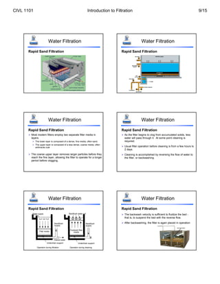
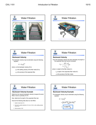
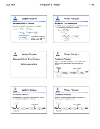
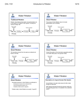
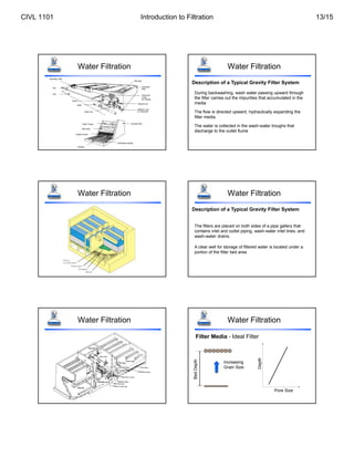
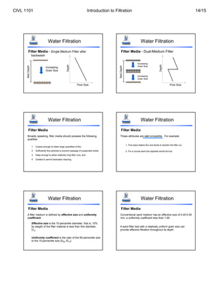
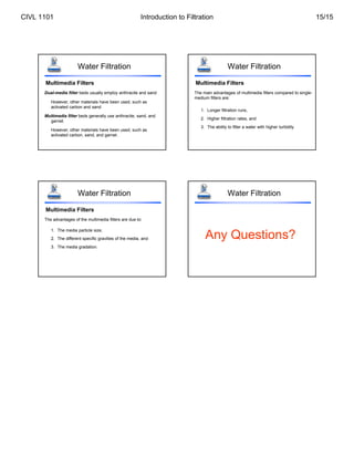
Water Treatment
 Water treatment describes those industrial-scale
processes used to make water more acceptable
for a desired end-use.
 These can include use for drinking water, industry,
medical and many other uses.
Water Treatment
 The goal of all water treatment process is to
remove existing contaminants in the water, or
reduce the concentration of such contaminants so
the water becomes fit for its desired end-use.
 One such use is returning water that has been
used back into the natural environment without
adverse ecological impact.
Water Treatment
Basis water treatment consists
of four processes:
 Coagulation/Flocculation
 Sedimentation
 Filtration
 Disinfection
Water Treatment
Coagulation
 This process helps removes
particles suspended in water.
 Chemicals are added to water
to form tiny sticky particles
called "floc" which attract the
particles.
Flocculation
 Flocculation refers to water
treatment processes that
combine or coagulate small
particles into larger particles,
which settle out of the water
as sediment.
Water Treatment Water Treatment
Sedimentation
 The heavy particles (floc)
settle to the bottom and the
clear water moves to filtration.
CIVL 1101 Introduction to Filtration 1/15
by ce.memphis.edu
Water Treatment
Filtration
 The water passes through
filters, some made of layers of
sand, gravel, and charcoal
that help remove even smaller
particles.
Water Treatment
Disinfection
 A small amount of chlorine is
added or some other
disinfection method is used to
kill any bacteria or
microorganisms that may be
in the water.
Water Treatment
1. Coagulation
2. Flocculation
3. Sedimentation
4. Filtration
5. Disinfection
6. Fluoridation
7. Stabilization
8. Collect and test water
samples
Water Treatment
1. Coagulation - Aluminum or iron salts plus chemicals
called polymers are mixed with the water to make the
particles in the water stick together.
2. Flocculation - The coagulated particles are slowly
mixed so that they can collide and form larger particles,
known as "floc."
3. Sedimentation - Water flows through a large tank
which allows the "floc" to settle to the bottom of the tank
and be removed.
4. Filtration - Water is passed through filters made of
sand and anthracite coal to filter out remaining
particles.
Water Treatment
5. Disinfection - Chlorine is added to reduce risks from
remaining bacteria and other disease-causing
organisms and to maintain water quality through the
distribution pipe system.
6. Fluoridation - Fluoride is added to provide dental
benefits.
7. Stabilization - Small amounts of lime (calcium
hydroxide) or sodium hydroxide are added to make the
water less corrosive to pipes and plumbing.
8. Collect and test water samples
Water Filtration
 Filtration is used to separate nonsettleable
solids from water and wastewater by passing it
through a porous medium
 The most common system is filtration through a
layered bed of granular media, usually a coarse
anthracite coal underlain by a finer sand.
CIVL 1101 Introduction to Filtration 2/15
Water Filtration
Filters may be classified according to the types of
media used as follows:
Single-media filters: These have one type of media,
usually sand or crushed anthracite coal.
Dual-media filters: These have two types of media,
usually crushed anthracite coal and sand.
Multi-media filters: These have three types of
media, usually crushed anthracite coal, sand, and
garnet.
Water Filtration
Filters may be classified according to the types of
media used as follows:
Water Filtration
 In water treatment all three types are used;
however, the dual- and multi-media filters are
becoming increasingly popular.
 Particle removal is accomplished only when the
particles make physical contact with the surface
of the filter medium.
Water Filtration
 Filtration was actually developed prior to the discovery of
the germ theory by Louis Pasteur in France.
 Louis Pasteur (1822 - 1895) was a
French chemist and microbiologist.
 He is remembered for his remarkable
breakthroughs in the causes and
preventions of diseases.
Water Filtration
 In the 1700s the first water filters for domestic application
were applied. These were made of wool, sponge and
charcoal.
 In 1804 the first actual municipal water treatment plant
designed by Robert Thom, was built in Paisley, Scotland.
 The water treatment was based on slow sand filtration, and
horse and cart distributed the water.
 Some three years later, the first water pipes were installed.
Water Filtration
 In 1854 it was discovered that a cholera epidemic spread
through water.
 The outbreak seemed less severe in areas where sand
filters were installed.
 British scientist John Snow found that the direct cause of
the outbreak was water pump contamination by sewage
water.
 He applied chlorine to purify the water, and this paved the
way for water disinfection.
CIVL 1101 Introduction to Filtration 3/15
Water Filtration
 John Snow (1813 - 1858) was an
English physician and a leader in the
adoption of anaesthesia and medical
hygiene.
 He is considered to be one of the
fathers of epidemiology, because of his
work in tracing the source of a cholera
outbreak in Soho, England, in 1854.
Water Filtration
Water Filtration Water Filtration
How does filtration work?
Let’s examine the physical and chemical mechanisms
of filtration
Water Filtration
Filter Media
Sedimentation
Straining
Interception
Floc Particles
Flocculation
Water Filtration
 Larger particles may be removed by straining
 Particles may also be removed by sedimentation
 Others may be intercepted by and adhere to the surface
of the medium due to inertia
 Filtration efficiency is greatly increased by destabilization
or coagulation of the particles prior to filtration
CIVL 1101 Introduction to Filtration 4/15
Water Filtration
 Gravity filtration through beds of granular media is the
most common method removing colloidal impurities in
water processing
 Initially, surface straining and interstitial removal results
in accumulation of deposits in the upper portion of the
filter media
Gravity Granular-Media Filtration
Water Filtration
 Because of the reduction in pore area, the velocity of
water through the remaining voids increases, shearing
off pieces of capture floc and carrying impurities deeper
into the filter bed
 The effective zone of removal passes deeper and
deeper into the filter
Gravity Granular-Media Filtration
Water Filtration
 Eventually, clean bed depth is no longer available and
breakthrough occurs, carrying solids out in the underflow
and causing termination of the filter run
Gravity Granular-Media Filtration
Water Filtration
Gravity Granular-Media Filtration
Water Filtration
 Turbidity is a measurement of the clarity of water run
 Clouded water is caused by suspended particles
scattering or absorbing the light
 Turbidity is an indirect measurement of the amount of
suspended matter in the water
Turbidity
Water Filtration
Turbidity
CIVL 1101 Introduction to Filtration 5/15
Water Filtration
 However, since solids of different sizes, shapes, and
surfaces reflect light differently, turbidity and suspended
solids do not correlate well.
 Turbidity is normally gauged with an instrument that
measures the amount of light scattered at an angle of 90°
from a source beam.
 The units of turbidity are usually in Nephelometric Turbidity
Units (NTU).
Turbidity
Water Filtration
 The early filtration units developed in Great Britain used a
process in which the hydraulic loading rate is relatively low.
 Typical slow sand filtration velocities are only
about 0.4 m/hr.
 At these low rates, the filtered contaminants do not
penetrate to an appreciable depth within the filtration
medium.
Slow Sand Filtration
Water Filtration
 The filter builds up a layer of filtered contaminants on the
surface, which becomes the active filtering medium
 Slow sand filters are cleaned by taking them off line and
draining them. The organic or contaminant layer is then
scraped off.
 The filter can then be restarted. After water quality reaches
an acceptable level, the filter can then be put back on line.
Slow Sand Filtration
Water Filtration
Slow Sand Filtration
Water Filtration
Slow Sand Filtration
Water Filtration
Rapid Sand Filtration
Filtration Type Application Rate
m/hr gal/ft2
-day
Slow Sand 0.04 to 0.4 340 to 3400
Rapid Sand 0.4 to 3.1 3400 to 26,000
 In rapid sand filtration much higher application velocities are
used
 Filtration occurs through the depth of the filter
 A comparison of rapid and slow sand filtration is shown in
the table below
CIVL 1101 Introduction to Filtration 6/15
Water Filtration
Rapid Sand Filtration
Filtration Type Application Rate
m/hr gal/ft2
-day
Slow Sand 0.04 to 0.4 340 to 3400
Rapid Sand 0.4 to 3.1 3400 to 26,000
 In the United States, filter application rates are often
expressed as volumetric flowrate per area, or
gal/min-ft2, which is actually a velocity with atypical units.
Hydraulic Loading Rate
Let’s compute the hydraulic loading rate on our filters in
lab:
Flowrate: 1,000 ml/min
Area of filter: 3.5 in. diameter filter
Flowrate
Loading Rate
Area

2
2
2
(3.5in.)
4
ml
1,000 1 144in.
min
3,785ml ft.
gallon

   2
gpm
3.954
ft

Water Filtration
Hydraulic Loading Rate
Let’s compute the hydraulic loading rate on our filters in
lab:
Flowrate: The one you used in lab last week.
Area of filter: 3.5 in. diameter filter
Flowrate
Loading Rate
Area


  
2
2
2
(3.5in.)
4
ml
1 144in.
min
3,785ml ft.
Flowrate gallon
Water Filtration
Hydraulic Loading Rate
Let’s compute the hydraulic loading rate on our filters in
lab:
Water Filtration
Flowrate (ml/min) Loading Rate (gpm/ft2)
1,000 3.954
1,250 4.943
1,500 5.932
Water Filtration
A hydraulic loading rate of 3.954 gpm/ft.2 could be
classified as:
1. A high-end direct filtration (1-6 gpm/ft.2)
2. A mid-range rapid filter (range of 2-10 gpm/ft.2
with 5 gpm/ft.2 normally the maximum design
rate)
Hydraulic Loading Rate Hydraulic Loading Rate
To convert the hydraulic loading rate to the U.S.
standard of gpd/ft.2, convert minutes to days
Flowrate
Loading Rate
Area

2
gpm min hr
3.954 60 24
hr day
ft.
  
2
gpd
5,694
ft.

Water Filtration
CIVL 1101 Introduction to Filtration 7/15
Water Filtration
A hydraulic loading rate of 5,694 gpd/ft.2 could be
qualifies as a rapid sand filter
Hydraulic Loading Rate
Filtration Type Application Rate
m/hr gal/ft2
-day
Slow Sand 0.04 to 0.4 340 to 3,400
Rapid Sand 0.4 to 3.1 3,400 to 26,000
Hydraulic Loading Rate
Let’s compute the hydraulic loading rate for flowrates in
class:
Flowrate: 1,250 and 1,500 ml/min
Area of filter: 3.5 in. diameter filter
Flowrate
Loading Rate
Area

 
2
2
2
(3.5in.)
4
ml
1 144in.
min
3,785m ft.
Flowrate gallon
l

  
Water Filtration
Hydraulic Loading Rate
Let’s compute the hydraulic loading rate for flowrates in
class:
Flowrate: 1,250 and 1,500 ml/min
Area of filter: 3.5 in. diameter filter
Flowrate of 1,250 ml/min  4.943 gpm/ft.2
Flowrate of 1,500 ml/min  5.932 gpm/ft.2
Water Filtration
Hydraulic Loading Rate
To convert the hydraulic loading rate to the U.S.
standard of gpd/ft.2, convert minutes to days
Flowrate
Loading Rate
Area

  
2
gpm min hr
4.943 60 24
hr day
ft.
 2
gpd
7,118
ft.
Water Filtration
Hydraulic Loading Rate
Let’s compute the hydraulic loading rate for flowrates in
class:
Flowrate: 1,250 and 1,500 ml/min
Area of filter: 3.5 in. diameter filter
Flowrate of 1,250 ml/min  7,118 gpd/ft.2
Flowrate of 1,500 ml/min  8,541 gpd/ft.2
Water Filtration Water Filtration
Rapid Sand Filtration
 The water above the filter provides the hydraulic pressure
(head) for the process.
 The filter medium is above a larger gravel, rock, or other
media for support.
 Below the rock is usually an underdrain support of some
type.
 The water flows through the filter and support media,
exiting from a pipe below.
CIVL 1101 Introduction to Filtration 8/15
Water Filtration
Rapid Sand Filtration
Water Filtration
Rapid Sand Filtration
Water Filtration
Rapid Sand Filtration
 Most modern filters employ two separate filter media in
layers:
 The lower layer is composed of a dense, fine media, often sand
 The upper layer is composed of a less dense, coarse media, often
anthracite coal
 The coarse upper layer removes larger particles before they
reach the fine layer, allowing the filter to operate for a longer
period before clogging.
Water Filtration
Rapid Sand Filtration
 As the filter begins to clog from accumulated solids, less
water will pass through it. At some point cleaning is
required.
 Usual filter operation before cleaning is from a few hours to
2 days.
 Cleaning is accomplished by reversing the flow of water to
the filter, or backwashing.
Water Filtration
Rapid Sand Filtration
Underdrain support Underdrain support
Filtered water
Backflush
supply
Backflush
supply
Backflush water out
Water supply
Filter media
Fluidized filter
media
Operation during filtration Operation during cleaning
Water Filtration
Rapid Sand Filtration
 The backwash velocity is sufficient to fluidize the bed -
that is, to suspend the bed with the reverse flow.
 After backwashing, the filter is again placed in operation
CIVL 1101 Introduction to Filtration 9/15
Water Filtration Water Filtration
http://www.fbleopold.com/flash/media.swf
Water Filtration
Backwash Velocity
The backwash velocity may be estimated using the following
equation
4.5
s e
v v 

where v is the backwash velocity (ft./s)
vs is the settling velocity of the filter media (ft./s)
e is the porosity of the expanded filter
Water Filtration
Backwash Velocity
Once the backwash velocity has been estimated, the depth of
the expanded filter bed may be computed
0.22
(1 )
1
e
s
L
L
v
v



 
  
 
where L is depth of the filter media (ft.)
Le is depth of the expanded filter media (ft.)
 is the porosity of the filter media
Water Filtration
Backwash Velocity Example
Determine the required backwash velocity to expand the sand
filters in lab to a porosity of 0.70.
Also, determine the depth of the expanded filter bed.
Assume the following data about our lab filters:
1. Depth of sand bed 0.5 ft.
2. Sand with a particle diameter of 0.5 mm or 0.02 in. with a settling velocity
of 0.27 ft./s
3. Sand porosity is 0.35
The backwash velocity may be estimated using the following
equation
4.5
s e
v v 

Water Filtration
Backwash Velocity Example
  
4.5
ft.
0.27 0.70
s

ft.
0.054
s

CIVL 1101 Introduction to Filtration 10/15
Determine the hydraulic loading rate of the backwash
Water Filtration
Backwash Velocity Example
ft.
0.054
s
Velocity 
3
2
ft.
0.054
ft. s

3
2 3
7.48gallons 86,400s
ft.
0.054 × ×
ft. s ft. day

2
gpd
34,900
ft.

The backwash loading rate
is about 7 times larger than
the filter loading rate
Water Filtration
Backwash Velocity Example
Once the backwash velocity has been estimated, the depth of
the expanded filter bed may be computed
0.22
(1 )
1
e
s
L
L
v
v



 
  
 
0.22
ft.
0.054
s
ft.
0.27
s
0.5ft.(1-0.35)
1-

 
 
 
 
1.09 ft.

Water Filtration
Backwash Velocity Group Problems
Switch presentations
Water Filtration
Traditional Filtration
A typical scheme for water filtration consists of flocculation
with a chemical coagulant and sedimentation prior to
filtration.
Influent Effluent
Polymer coagulant
Rapid mixing
t = 30 minutes
Alum or other
coagulant
Flocculation
t = 15-30 minutes
Sedimentation
t = 1-4 hours
Filtration
t = 1-10 gpm/ft.2
Water Filtration
Traditional Filtration
Under the force of gravity water passes downward through
the media that collect the floc and particles.
Influent Effluent
Polymer coagulant
Rapid mixing
t = 30 minutes
Alum or other
coagulant
Flocculation
t = 15-30 minutes
Sedimentation
t = 1-4 hours
Filtration
t = 1-10 gpm/ft.2
Water Filtration
Traditional Filtration
When the media become filled or solids break through, a
filter bed is cleaned by backwashing.
Influent Effluent
Polymer coagulant
Rapid mixing
t = 30 minutes
Alum or other
coagulant
Flocculation
t = 15-30 minutes
Sedimentation
t = 1-4 hours
Filtration
t = 1-10 gpm/ft.2
CIVL 1101 Introduction to Filtration 11/15
Water Filtration
Traditional Filtration
Filtration rates following flocculation and sedimentation are
in the range of 2-10 gpm/ft.2 with 5 gpm/ft.2 normally the
maximum design rate.
Influent Effluent
Polymer coagulant
Rapid mixing
t = 30 minutes
Alum or other
coagulant
Flocculation
t = 15-30 minutes
Sedimentation
t = 1-4 hours
Filtration
t = 1-10 gpm/ft.2
Water Filtration
Direct Filtration
The process of direct filtration does not include
sedimentation prior to filtration.
Filtration
R = 1 - 10 gpm/ft.2
Influent Effluent
Polymer coagulant
Rapid mixing
t = 30 minutes
Alum or other
coagulant
Optional mixing
T > 30 minutes
Water Filtration
Direct Filtration
The impurities removed from the water are collected and
stored in the filter.
Filtration
R = 1 - 10 gpm/ft.2
Influent Effluent
Polymer coagulant
Rapid mixing
t = 30 minutes
Alum or other
coagulant
Optional mixing
T > 30 minutes
Water Filtration
Direct Filtration
Contact flocculation of the chemically coagulated particles
in the water takes place in the granular media.
Filtration
R = 1 - 10 gpm/ft.2
Influent Effluent
Polymer coagulant
Rapid mixing
t = 30 minutes
Alum or other
coagulant
Optional mixing
T > 30 minutes
Water Filtration
Direct Filtration
Successful advances in direct filtration are attributed to:
Development of coarse-to-fine multimedia filters
Improved backwashing systems, and
Availability of better polymer coagulants
Filtration rates in direct filtration are usually 1-6 gpm/ft.2
Water Filtration
Description of a Typical Gravity Filter System
During filtration, the water enters above the filter media
through an inlet flume.
After passing downward through the granular media and
the supporting gravel bed, it is collected in the underdrain
system
CIVL 1101 Introduction to Filtration 12/15
Water Filtration
Drain
Waste
Wash Line
Wash Trough
Filter Sand
Graded Gravel
Manifold
Perforated Laterals
Concrete Wall
Effluent Line
to Clearwell
Influent Line
Hydraulic
Lines
for Values
Concrete
Wall
Filter Bed
Operating Table
Floor
Floor
Water Filtration
During backwashing, wash water passing upward through
the filter carries out the impurities that accumulated in the
media
The flow is directed upward, hydraulically expanding the
filter media
The water is collected in the wash-water troughs that
discharge to the outlet flume
Description of a Typical Gravity Filter System
Water Filtration Water Filtration
The filters are placed on both sides of a pipe gallery that
contains inlet and outlet piping, wash-water inlet lines, and
wash-water drains.
A clear well for storage of filtered water is located under a
portion of the filter bed area
Description of a Typical Gravity Filter System
Water Filtration Water Filtration
Filter Media - Ideal Filter
Increasing
Grain Size
Bed
Depth
Pore Size
Depth
CIVL 1101 Introduction to Filtration 13/15
Water Filtration
Filter Media - Single Medium Filter after
backwash
Increasing
Grain Size
Bed
Depth
Pore Size
Depth
Water Filtration
Filter Media - Dual-Medium Filter
Increasing
Grain Size
Bed
Depth
Increasing
Grain Size
Pore Size
Depth
Water Filtration
Filter Media
Broadly speaking, filter media should possess the following
qualities:
1. Coarse enough to retain large quantities of floc,
2. Sufficiently fine particles to prevent passage of suspended solids,
3. Deep enough to allow relatively long filter runs, and
4. Graded to permit backwash cleaning.
Water Filtration
Filter Media
These attributes are not compatible. For example:
1. Fine sand retains floc and tends to shorten the filter run
2. For a course sand the opposite would be true
Water Filtration
Filter Media
A filter medium is defined by effective size and uniformity
coefficient.
Effective size is the 10-percentile diameter; that is, 10%
by weight of the filter material is less than this diameter,
D10
Uniformity coefficient is the ratio of the 60-percentile size
to the 10-percentile size (D60 /D10)
Water Filtration
Filter Media
Conventional sand medium has an effective size of 0.45-0.55
mm, a uniformity coefficient less than 1.65
A sand filter bed with a relatively uniform grain size can
provide effective filtration throughout its depth
CIVL 1101 Introduction to Filtration 14/15
Water Filtration
Multimedia Filters
Dual-media filter beds usually employ anthracite and sand
However, other materials have been used, such as
activated carbon and sand
Multimedia filter beds generally use anthracite, sand, and
garnet.
However, other materials have been used, such as
activated carbon, sand, and garnet.
Water Filtration
Multimedia Filters
The main advantages of multimedia filters compared to single-
medium filters are:
1. Longer filtration runs,
2. Higher filtration rates, and
3. The ability to filter a water with higher turbidity
Water Filtration
Multimedia Filters
The advantages of the multimedia filters are due to:
1. The media particle size,
2. The different specific gravities of the media, and
3. The media gradation.
Water Filtration
Any Questions?
CIVL 1101 Introduction to Filtration 15/15

Filtration_introduction.pdf

  • 1.
    Water Treatment  Watertreatment describes those industrial-scale processes used to make water more acceptable for a desired end-use.  These can include use for drinking water, industry, medical and many other uses. Water Treatment  The goal of all water treatment process is to remove existing contaminants in the water, or reduce the concentration of such contaminants so the water becomes fit for its desired end-use.  One such use is returning water that has been used back into the natural environment without adverse ecological impact. Water Treatment Basis water treatment consists of four processes:  Coagulation/Flocculation  Sedimentation  Filtration  Disinfection Water Treatment Coagulation  This process helps removes particles suspended in water.  Chemicals are added to water to form tiny sticky particles called "floc" which attract the particles. Flocculation  Flocculation refers to water treatment processes that combine or coagulate small particles into larger particles, which settle out of the water as sediment. Water Treatment Water Treatment Sedimentation  The heavy particles (floc) settle to the bottom and the clear water moves to filtration. CIVL 1101 Introduction to Filtration 1/15 by ce.memphis.edu
  • 2.
    Water Treatment Filtration  Thewater passes through filters, some made of layers of sand, gravel, and charcoal that help remove even smaller particles. Water Treatment Disinfection  A small amount of chlorine is added or some other disinfection method is used to kill any bacteria or microorganisms that may be in the water. Water Treatment 1. Coagulation 2. Flocculation 3. Sedimentation 4. Filtration 5. Disinfection 6. Fluoridation 7. Stabilization 8. Collect and test water samples Water Treatment 1. Coagulation - Aluminum or iron salts plus chemicals called polymers are mixed with the water to make the particles in the water stick together. 2. Flocculation - The coagulated particles are slowly mixed so that they can collide and form larger particles, known as "floc." 3. Sedimentation - Water flows through a large tank which allows the "floc" to settle to the bottom of the tank and be removed. 4. Filtration - Water is passed through filters made of sand and anthracite coal to filter out remaining particles. Water Treatment 5. Disinfection - Chlorine is added to reduce risks from remaining bacteria and other disease-causing organisms and to maintain water quality through the distribution pipe system. 6. Fluoridation - Fluoride is added to provide dental benefits. 7. Stabilization - Small amounts of lime (calcium hydroxide) or sodium hydroxide are added to make the water less corrosive to pipes and plumbing. 8. Collect and test water samples Water Filtration  Filtration is used to separate nonsettleable solids from water and wastewater by passing it through a porous medium  The most common system is filtration through a layered bed of granular media, usually a coarse anthracite coal underlain by a finer sand. CIVL 1101 Introduction to Filtration 2/15
  • 3.
    Water Filtration Filters maybe classified according to the types of media used as follows: Single-media filters: These have one type of media, usually sand or crushed anthracite coal. Dual-media filters: These have two types of media, usually crushed anthracite coal and sand. Multi-media filters: These have three types of media, usually crushed anthracite coal, sand, and garnet. Water Filtration Filters may be classified according to the types of media used as follows: Water Filtration  In water treatment all three types are used; however, the dual- and multi-media filters are becoming increasingly popular.  Particle removal is accomplished only when the particles make physical contact with the surface of the filter medium. Water Filtration  Filtration was actually developed prior to the discovery of the germ theory by Louis Pasteur in France.  Louis Pasteur (1822 - 1895) was a French chemist and microbiologist.  He is remembered for his remarkable breakthroughs in the causes and preventions of diseases. Water Filtration  In the 1700s the first water filters for domestic application were applied. These were made of wool, sponge and charcoal.  In 1804 the first actual municipal water treatment plant designed by Robert Thom, was built in Paisley, Scotland.  The water treatment was based on slow sand filtration, and horse and cart distributed the water.  Some three years later, the first water pipes were installed. Water Filtration  In 1854 it was discovered that a cholera epidemic spread through water.  The outbreak seemed less severe in areas where sand filters were installed.  British scientist John Snow found that the direct cause of the outbreak was water pump contamination by sewage water.  He applied chlorine to purify the water, and this paved the way for water disinfection. CIVL 1101 Introduction to Filtration 3/15
  • 4.
    Water Filtration  JohnSnow (1813 - 1858) was an English physician and a leader in the adoption of anaesthesia and medical hygiene.  He is considered to be one of the fathers of epidemiology, because of his work in tracing the source of a cholera outbreak in Soho, England, in 1854. Water Filtration Water Filtration Water Filtration How does filtration work? Let’s examine the physical and chemical mechanisms of filtration Water Filtration Filter Media Sedimentation Straining Interception Floc Particles Flocculation Water Filtration  Larger particles may be removed by straining  Particles may also be removed by sedimentation  Others may be intercepted by and adhere to the surface of the medium due to inertia  Filtration efficiency is greatly increased by destabilization or coagulation of the particles prior to filtration CIVL 1101 Introduction to Filtration 4/15
  • 5.
    Water Filtration  Gravityfiltration through beds of granular media is the most common method removing colloidal impurities in water processing  Initially, surface straining and interstitial removal results in accumulation of deposits in the upper portion of the filter media Gravity Granular-Media Filtration Water Filtration  Because of the reduction in pore area, the velocity of water through the remaining voids increases, shearing off pieces of capture floc and carrying impurities deeper into the filter bed  The effective zone of removal passes deeper and deeper into the filter Gravity Granular-Media Filtration Water Filtration  Eventually, clean bed depth is no longer available and breakthrough occurs, carrying solids out in the underflow and causing termination of the filter run Gravity Granular-Media Filtration Water Filtration Gravity Granular-Media Filtration Water Filtration  Turbidity is a measurement of the clarity of water run  Clouded water is caused by suspended particles scattering or absorbing the light  Turbidity is an indirect measurement of the amount of suspended matter in the water Turbidity Water Filtration Turbidity CIVL 1101 Introduction to Filtration 5/15
  • 6.
    Water Filtration  However,since solids of different sizes, shapes, and surfaces reflect light differently, turbidity and suspended solids do not correlate well.  Turbidity is normally gauged with an instrument that measures the amount of light scattered at an angle of 90° from a source beam.  The units of turbidity are usually in Nephelometric Turbidity Units (NTU). Turbidity Water Filtration  The early filtration units developed in Great Britain used a process in which the hydraulic loading rate is relatively low.  Typical slow sand filtration velocities are only about 0.4 m/hr.  At these low rates, the filtered contaminants do not penetrate to an appreciable depth within the filtration medium. Slow Sand Filtration Water Filtration  The filter builds up a layer of filtered contaminants on the surface, which becomes the active filtering medium  Slow sand filters are cleaned by taking them off line and draining them. The organic or contaminant layer is then scraped off.  The filter can then be restarted. After water quality reaches an acceptable level, the filter can then be put back on line. Slow Sand Filtration Water Filtration Slow Sand Filtration Water Filtration Slow Sand Filtration Water Filtration Rapid Sand Filtration Filtration Type Application Rate m/hr gal/ft2 -day Slow Sand 0.04 to 0.4 340 to 3400 Rapid Sand 0.4 to 3.1 3400 to 26,000  In rapid sand filtration much higher application velocities are used  Filtration occurs through the depth of the filter  A comparison of rapid and slow sand filtration is shown in the table below CIVL 1101 Introduction to Filtration 6/15
  • 7.
    Water Filtration Rapid SandFiltration Filtration Type Application Rate m/hr gal/ft2 -day Slow Sand 0.04 to 0.4 340 to 3400 Rapid Sand 0.4 to 3.1 3400 to 26,000  In the United States, filter application rates are often expressed as volumetric flowrate per area, or gal/min-ft2, which is actually a velocity with atypical units. Hydraulic Loading Rate Let’s compute the hydraulic loading rate on our filters in lab: Flowrate: 1,000 ml/min Area of filter: 3.5 in. diameter filter Flowrate Loading Rate Area  2 2 2 (3.5in.) 4 ml 1,000 1 144in. min 3,785ml ft. gallon     2 gpm 3.954 ft  Water Filtration Hydraulic Loading Rate Let’s compute the hydraulic loading rate on our filters in lab: Flowrate: The one you used in lab last week. Area of filter: 3.5 in. diameter filter Flowrate Loading Rate Area      2 2 2 (3.5in.) 4 ml 1 144in. min 3,785ml ft. Flowrate gallon Water Filtration Hydraulic Loading Rate Let’s compute the hydraulic loading rate on our filters in lab: Water Filtration Flowrate (ml/min) Loading Rate (gpm/ft2) 1,000 3.954 1,250 4.943 1,500 5.932 Water Filtration A hydraulic loading rate of 3.954 gpm/ft.2 could be classified as: 1. A high-end direct filtration (1-6 gpm/ft.2) 2. A mid-range rapid filter (range of 2-10 gpm/ft.2 with 5 gpm/ft.2 normally the maximum design rate) Hydraulic Loading Rate Hydraulic Loading Rate To convert the hydraulic loading rate to the U.S. standard of gpd/ft.2, convert minutes to days Flowrate Loading Rate Area  2 gpm min hr 3.954 60 24 hr day ft.    2 gpd 5,694 ft.  Water Filtration CIVL 1101 Introduction to Filtration 7/15
  • 8.
    Water Filtration A hydraulicloading rate of 5,694 gpd/ft.2 could be qualifies as a rapid sand filter Hydraulic Loading Rate Filtration Type Application Rate m/hr gal/ft2 -day Slow Sand 0.04 to 0.4 340 to 3,400 Rapid Sand 0.4 to 3.1 3,400 to 26,000 Hydraulic Loading Rate Let’s compute the hydraulic loading rate for flowrates in class: Flowrate: 1,250 and 1,500 ml/min Area of filter: 3.5 in. diameter filter Flowrate Loading Rate Area    2 2 2 (3.5in.) 4 ml 1 144in. min 3,785m ft. Flowrate gallon l     Water Filtration Hydraulic Loading Rate Let’s compute the hydraulic loading rate for flowrates in class: Flowrate: 1,250 and 1,500 ml/min Area of filter: 3.5 in. diameter filter Flowrate of 1,250 ml/min  4.943 gpm/ft.2 Flowrate of 1,500 ml/min  5.932 gpm/ft.2 Water Filtration Hydraulic Loading Rate To convert the hydraulic loading rate to the U.S. standard of gpd/ft.2, convert minutes to days Flowrate Loading Rate Area     2 gpm min hr 4.943 60 24 hr day ft.  2 gpd 7,118 ft. Water Filtration Hydraulic Loading Rate Let’s compute the hydraulic loading rate for flowrates in class: Flowrate: 1,250 and 1,500 ml/min Area of filter: 3.5 in. diameter filter Flowrate of 1,250 ml/min  7,118 gpd/ft.2 Flowrate of 1,500 ml/min  8,541 gpd/ft.2 Water Filtration Water Filtration Rapid Sand Filtration  The water above the filter provides the hydraulic pressure (head) for the process.  The filter medium is above a larger gravel, rock, or other media for support.  Below the rock is usually an underdrain support of some type.  The water flows through the filter and support media, exiting from a pipe below. CIVL 1101 Introduction to Filtration 8/15
  • 9.
    Water Filtration Rapid SandFiltration Water Filtration Rapid Sand Filtration Water Filtration Rapid Sand Filtration  Most modern filters employ two separate filter media in layers:  The lower layer is composed of a dense, fine media, often sand  The upper layer is composed of a less dense, coarse media, often anthracite coal  The coarse upper layer removes larger particles before they reach the fine layer, allowing the filter to operate for a longer period before clogging. Water Filtration Rapid Sand Filtration  As the filter begins to clog from accumulated solids, less water will pass through it. At some point cleaning is required.  Usual filter operation before cleaning is from a few hours to 2 days.  Cleaning is accomplished by reversing the flow of water to the filter, or backwashing. Water Filtration Rapid Sand Filtration Underdrain support Underdrain support Filtered water Backflush supply Backflush supply Backflush water out Water supply Filter media Fluidized filter media Operation during filtration Operation during cleaning Water Filtration Rapid Sand Filtration  The backwash velocity is sufficient to fluidize the bed - that is, to suspend the bed with the reverse flow.  After backwashing, the filter is again placed in operation CIVL 1101 Introduction to Filtration 9/15
  • 10.
    Water Filtration WaterFiltration http://www.fbleopold.com/flash/media.swf Water Filtration Backwash Velocity The backwash velocity may be estimated using the following equation 4.5 s e v v   where v is the backwash velocity (ft./s) vs is the settling velocity of the filter media (ft./s) e is the porosity of the expanded filter Water Filtration Backwash Velocity Once the backwash velocity has been estimated, the depth of the expanded filter bed may be computed 0.22 (1 ) 1 e s L L v v           where L is depth of the filter media (ft.) Le is depth of the expanded filter media (ft.)  is the porosity of the filter media Water Filtration Backwash Velocity Example Determine the required backwash velocity to expand the sand filters in lab to a porosity of 0.70. Also, determine the depth of the expanded filter bed. Assume the following data about our lab filters: 1. Depth of sand bed 0.5 ft. 2. Sand with a particle diameter of 0.5 mm or 0.02 in. with a settling velocity of 0.27 ft./s 3. Sand porosity is 0.35 The backwash velocity may be estimated using the following equation 4.5 s e v v   Water Filtration Backwash Velocity Example    4.5 ft. 0.27 0.70 s  ft. 0.054 s  CIVL 1101 Introduction to Filtration 10/15
  • 11.
    Determine the hydraulicloading rate of the backwash Water Filtration Backwash Velocity Example ft. 0.054 s Velocity  3 2 ft. 0.054 ft. s  3 2 3 7.48gallons 86,400s ft. 0.054 × × ft. s ft. day  2 gpd 34,900 ft.  The backwash loading rate is about 7 times larger than the filter loading rate Water Filtration Backwash Velocity Example Once the backwash velocity has been estimated, the depth of the expanded filter bed may be computed 0.22 (1 ) 1 e s L L v v           0.22 ft. 0.054 s ft. 0.27 s 0.5ft.(1-0.35) 1-          1.09 ft.  Water Filtration Backwash Velocity Group Problems Switch presentations Water Filtration Traditional Filtration A typical scheme for water filtration consists of flocculation with a chemical coagulant and sedimentation prior to filtration. Influent Effluent Polymer coagulant Rapid mixing t = 30 minutes Alum or other coagulant Flocculation t = 15-30 minutes Sedimentation t = 1-4 hours Filtration t = 1-10 gpm/ft.2 Water Filtration Traditional Filtration Under the force of gravity water passes downward through the media that collect the floc and particles. Influent Effluent Polymer coagulant Rapid mixing t = 30 minutes Alum or other coagulant Flocculation t = 15-30 minutes Sedimentation t = 1-4 hours Filtration t = 1-10 gpm/ft.2 Water Filtration Traditional Filtration When the media become filled or solids break through, a filter bed is cleaned by backwashing. Influent Effluent Polymer coagulant Rapid mixing t = 30 minutes Alum or other coagulant Flocculation t = 15-30 minutes Sedimentation t = 1-4 hours Filtration t = 1-10 gpm/ft.2 CIVL 1101 Introduction to Filtration 11/15
  • 12.
    Water Filtration Traditional Filtration Filtrationrates following flocculation and sedimentation are in the range of 2-10 gpm/ft.2 with 5 gpm/ft.2 normally the maximum design rate. Influent Effluent Polymer coagulant Rapid mixing t = 30 minutes Alum or other coagulant Flocculation t = 15-30 minutes Sedimentation t = 1-4 hours Filtration t = 1-10 gpm/ft.2 Water Filtration Direct Filtration The process of direct filtration does not include sedimentation prior to filtration. Filtration R = 1 - 10 gpm/ft.2 Influent Effluent Polymer coagulant Rapid mixing t = 30 minutes Alum or other coagulant Optional mixing T > 30 minutes Water Filtration Direct Filtration The impurities removed from the water are collected and stored in the filter. Filtration R = 1 - 10 gpm/ft.2 Influent Effluent Polymer coagulant Rapid mixing t = 30 minutes Alum or other coagulant Optional mixing T > 30 minutes Water Filtration Direct Filtration Contact flocculation of the chemically coagulated particles in the water takes place in the granular media. Filtration R = 1 - 10 gpm/ft.2 Influent Effluent Polymer coagulant Rapid mixing t = 30 minutes Alum or other coagulant Optional mixing T > 30 minutes Water Filtration Direct Filtration Successful advances in direct filtration are attributed to: Development of coarse-to-fine multimedia filters Improved backwashing systems, and Availability of better polymer coagulants Filtration rates in direct filtration are usually 1-6 gpm/ft.2 Water Filtration Description of a Typical Gravity Filter System During filtration, the water enters above the filter media through an inlet flume. After passing downward through the granular media and the supporting gravel bed, it is collected in the underdrain system CIVL 1101 Introduction to Filtration 12/15
  • 13.
    Water Filtration Drain Waste Wash Line WashTrough Filter Sand Graded Gravel Manifold Perforated Laterals Concrete Wall Effluent Line to Clearwell Influent Line Hydraulic Lines for Values Concrete Wall Filter Bed Operating Table Floor Floor Water Filtration During backwashing, wash water passing upward through the filter carries out the impurities that accumulated in the media The flow is directed upward, hydraulically expanding the filter media The water is collected in the wash-water troughs that discharge to the outlet flume Description of a Typical Gravity Filter System Water Filtration Water Filtration The filters are placed on both sides of a pipe gallery that contains inlet and outlet piping, wash-water inlet lines, and wash-water drains. A clear well for storage of filtered water is located under a portion of the filter bed area Description of a Typical Gravity Filter System Water Filtration Water Filtration Filter Media - Ideal Filter Increasing Grain Size Bed Depth Pore Size Depth CIVL 1101 Introduction to Filtration 13/15
  • 14.
    Water Filtration Filter Media- Single Medium Filter after backwash Increasing Grain Size Bed Depth Pore Size Depth Water Filtration Filter Media - Dual-Medium Filter Increasing Grain Size Bed Depth Increasing Grain Size Pore Size Depth Water Filtration Filter Media Broadly speaking, filter media should possess the following qualities: 1. Coarse enough to retain large quantities of floc, 2. Sufficiently fine particles to prevent passage of suspended solids, 3. Deep enough to allow relatively long filter runs, and 4. Graded to permit backwash cleaning. Water Filtration Filter Media These attributes are not compatible. For example: 1. Fine sand retains floc and tends to shorten the filter run 2. For a course sand the opposite would be true Water Filtration Filter Media A filter medium is defined by effective size and uniformity coefficient. Effective size is the 10-percentile diameter; that is, 10% by weight of the filter material is less than this diameter, D10 Uniformity coefficient is the ratio of the 60-percentile size to the 10-percentile size (D60 /D10) Water Filtration Filter Media Conventional sand medium has an effective size of 0.45-0.55 mm, a uniformity coefficient less than 1.65 A sand filter bed with a relatively uniform grain size can provide effective filtration throughout its depth CIVL 1101 Introduction to Filtration 14/15
  • 15.
    Water Filtration Multimedia Filters Dual-mediafilter beds usually employ anthracite and sand However, other materials have been used, such as activated carbon and sand Multimedia filter beds generally use anthracite, sand, and garnet. However, other materials have been used, such as activated carbon, sand, and garnet. Water Filtration Multimedia Filters The main advantages of multimedia filters compared to single- medium filters are: 1. Longer filtration runs, 2. Higher filtration rates, and 3. The ability to filter a water with higher turbidity Water Filtration Multimedia Filters The advantages of the multimedia filters are due to: 1. The media particle size, 2. The different specific gravities of the media, and 3. The media gradation. Water Filtration Any Questions? CIVL 1101 Introduction to Filtration 15/15