Production of Ferroalloys
FerrochromeProduction
Department of Metallurgical and Materials Engineering
National Institute of Technology
Durgapur-713209
Satadal Ghorai
MME613: SG, MME NIT Durgapur
3.
DISCLAIMER
The study materials/presentationsare solely
meant for academic purposes and they can be
reused, reproduced, modified, and distributed
by others for academic purposes only with
proper acknowledgements
MME613: SG, MME NIT Durgapur
4.
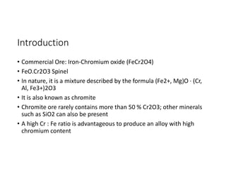
Introduction
• Commercial Ore:Iron-Chromium oxide (FeCr2O4)
• FeO.Cr2O3 Spinel
• In nature, it is a mixture described by the formula (Fe2+, Mg)O · (Cr,
Al, Fe3+)2O3
• It is also known as chromite
• Chromite ore rarely contains more than 50 % Cr2O3; other minerals
such as SiO2 can also be present
• A high Cr : Fe ratio is advantageous to produce an alloy with high
chromium content
5.
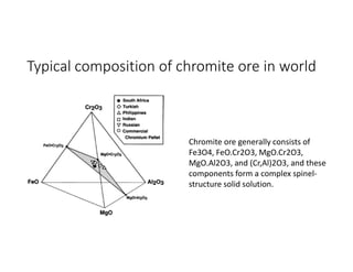
Typical composition ofchromite ore in world
Chromite ore generally consists of
Fe3O4, FeO.Cr2O3, MgO.Cr2O3,
MgO.Al2O3, and (Cr,Al)2O3, and these
components form a complex spinel-
structure solid solution.
6.
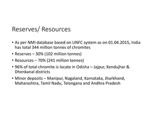
Reserves/ Resources
• Asper NMI database based on UNFC system as on 01.04.2015, India
has total 344 million tonnes of chromites
• Reserves – 30% (102 million tonnes)
• Resources – 70% (241 million tonnes)
• 96% of total chromite is locate in Odisha – Jajpur, Kendujhar &
Dhenkanal districts
• Minor deposits – Manipur, Nagaland, Karnataka, Jharkhand,
Maharashtra, Tamil Nadu, Telangana and Andhra Pradesh
7.
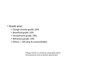
• Grade wise:
•Charge chrome grade: 31%
• Beneficial grade: 25%
• Ferrochrome grade: 18%
• Refractory grade: 14%
• Others – 12% (low & unclassifiable)
Charge chrome is a relatively cheap high carbon
ferrochromium with no definite specification
Environmental issue
• Hexavalentchromium – contaminate water bodies, it is carcinogenic
• Remedy : ferrous sulphate solution converts the hexavalent to
trivalent form which is non-carcinogenic
10.
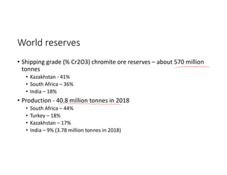
World reserves
• Shippinggrade (% Cr2O3) chromite ore reserves – about 570 million
tonnes
• Kazakhstan - 41%
• South Africa – 36%
• India – 18%
• Production - 40.8 million tonnes in 2018
• South Africa – 44%
• Turkey – 18%
• Kazakhstan – 17%
• India – 9% (3.78 million tonnes in 2018)
11.
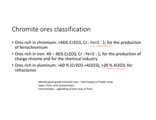
Chromite ores classification
•Ores rich in chromium: >46% Cr2O3, Cr : Fe>2 : 1; for the production
of ferrochromium
• Ores rich in iron: 40 – 46% Cr2O3, Cr : Fe<2 : 1; for the production of
charge chrome and for the chemical industry
• Ores rich in aluminum: >60 % (Cr2O3 +Al2O3), >20 % Al2O3; for
refractories
Metallurgical-grade chromite ores - hard lumpy or friable lump
types, fines, and concentrates.
Concentrates - upgrading of lean ores or fines
12.
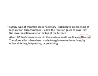
• Lumpy typeof chromite ore is necessary - submerged arc smelting of
high-carbon ferrochromium – allow the reaction gases to pass from
the lower reaction zone to the top of the furnace
• About 80 % of chromite ores in the western world are fines (<10 mm).
Therefore, efforts have been made to agglomerate these fines, by
either sintering, briquetting, or pelletizing
13.
Phase equilibria
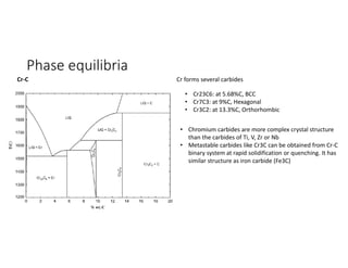
Cr-C Crforms several carbides
• Cr23C6: at 5.68%C, BCC
• Cr7C3: at 9%C, Hexagonal
• Cr3C2: at 13.3%C, Orthorhombic
• Chromium carbides are more complex crystal structure
than the carbides of Ti, V, Zr or Nb
• Metastable carbides like Cr3C can be obtained from Cr-C
binary system at rapid solidification or quenching. It has
similar structure as iron carbide (Fe3C)
14.
Cr-O
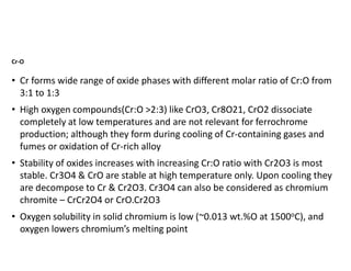
• Cr formswide range of oxide phases with different molar ratio of Cr:O from
3:1 to 1:3
• High oxygen compounds(Cr:O >2:3) like CrO3, Cr8O21, CrO2 dissociate
completely at low temperatures and are not relevant for ferrochrome
production; although they form during cooling of Cr-containing gases and
fumes or oxidation of Cr-rich alloy
• Stability of oxides increases with increasing Cr:O ratio with Cr2O3 is most
stable. Cr3O4 & CrO are stable at high temperature only. Upon cooling they
are decompose to Cr & Cr2O3. Cr3O4 can also be considered as chromium
chromite – CrCr2O4 or CrO.Cr2O3
• Oxygen solubility in solid chromium is low (~0.013 wt.%O at 1500oC), and
oxygen lowers chromium’s melting point
15.
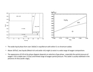
• The oxideliquid phase form over 1663oC in equilibrium with either Cr or chromium oxides
• Above 1875oC, two liquids (Metal-rich and oxide rich) might co-exist in a wide range of oxygen compositions
• The appearance of CrO at the phase diagram depends on selection of gas phase , especially the partial pressure of
oxygen. CrO is stable over 1715oC and limited range of oxygen partial pressure. This oxide is usually stabilized in the
presence of silica (acidic slags),
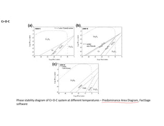
• +++ markson the diagram (previous slide) indicate isobar line of 1 atm total pressure
• If these marks exist anywhere in the phase stability field, it means that
thermodynamically there is a possibility of obtaining that phase in the system under a
particular combination of temperature and partial pressures of CO an CO2
• At 1800K, it is not possible to get metallic Cr in Cr-C-O system; only oxide Cr2O3 (at high
CO2 fraction) or carbides Cr23C6 & Cr3C2 (at high CO fraction) are possible if total
system pressure is maintained at 1 atm.
• With increasing temperature to 2000K leads to appearance and extension of Cr3O4 &
CrO phase field
• At 2200K, metallic Cr phase field appears; but, very limited range CO2 partial pressure.
Eventhough Cr-oxide might be reduced by C at high temperature, it is unlikely to be
practically feasible to produce pure Cr due to difficulties in controlling the local gas
atmosphere
• Thermodynamics of the Cr-C-O equilibria implies that the most practical method of Cr-
oxide reduction by carbon to produce Cr is realized by decreasing the activity of Cr in the
melt with the addition of Fe or Si
18.
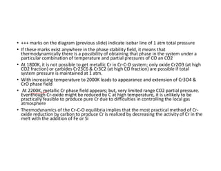
Thermodynamics - Reductionby CO
• At 1873K, ∆Go = 91295J, reaction is not feasible
• Equilibrium constant, K at 1873, is 2.84 x 10-3 = pCO2/pCO assuming
activity of Cr2O3 and Cr are unity
• The CO utilisation efficiency(%)= [pCO2 /( pCO+ pCO2 )]eqbm x 100
=0.284%
• Similarly, at 1923K, CO utilization efficiency = 0.33%
• So CO is not an efficient reducing agent for Cr2O3 in reduction of
chromite
19.
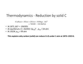
Thermodynamics - Reductionby solid C
• At 1873, ∆Go = -194305J
• At equilibrium, K = 262433 =(pCO)3 , pCO = 64 atm
• At 1923K, pCO = 99 atm
This explains why carbon (solid) can reduce Cr2O3 under 1 atm at 1873–1923 K.
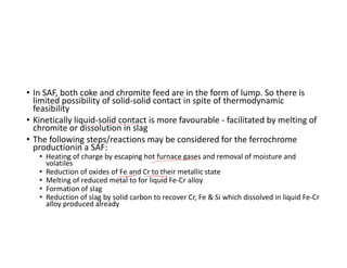
• In SAF,both coke and chromite feed are in the form of lump. So there is
limited possibility of solid-solid contact in spite of thermodynamic
feasibility
• Kinetically liquid-solid contact is more favourable - facilitated by melting of
chromite or dissolution in slag
• The following steps/reactions may be considered for the ferrochrome
productionin a SAF:
• Heating of charge by escaping hot furnace gases and removal of moisture and
volatiles
• Reduction of oxides of Fe and Cr to their metallic state
• Melting of reduced metal to for liquid Fe-Cr alloy
• Formation of slag
• Reduction of slag by solid carbon to recover Cr, Fe & Si which dissolved in liquid Fe-Cr
alloy produced already
22.
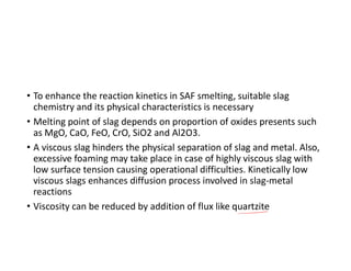
• To enhancethe reaction kinetics in SAF smelting, suitable slag
chemistry and its physical characteristics is necessary
• Melting point of slag depends on proportion of oxides presents such
as MgO, CaO, FeO, CrO, SiO2 and Al2O3.
• A viscous slag hinders the physical separation of slag and metal. Also,
excessive foaming may take place in case of highly viscous slag with
low surface tension causing operational difficulties. Kinetically low
viscous slags enhances diffusion process involved in slag-metal
reactions
• Viscosity can be reduced by addition of flux like quartzite
23.
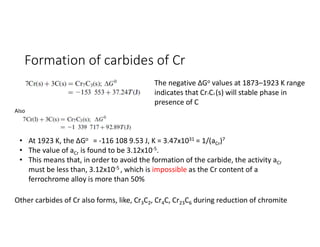
Formation of carbidesof Cr
The negative ∆Go values at 1873–1923 K range
indicates that Cr7C3 (s) will stable phase in
presence of C
Also
• At 1923 K, the ∆Go = -116 108 9.53 J, K = 3.47x1031 = 1/(aCr)7
• The value of aCr is found to be 3.12x10⁻⁵.
• This means that, in order to avoid the formation of the carbide, the activity aCr
must be less than, 3.12x10⁻⁵ , which is impossible as the Cr content of a
ferrochrome alloy is more than 50%
Other carbides of Cr also forms, like, Cr3C2, Cr4C, Cr23C6 during reduction of chromite
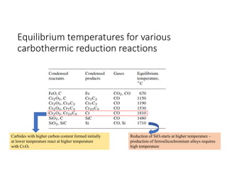
Equilibrium temperatures forvarious
carbothermic reduction reactions
Carbides with higher carbon content formed initially
at lower temperature react at higher temperature
with Cr2O3
Reduction of SiO2 starts at higher temperature –
production of ferrosilicochromium alloys requires
high temperature
26.
Raw materials
• Ore+ Flux + Reductant
• Ore - lump, pellet, briquette or sinter
• Reductant – Coke, anthracite, char or coal
• Fluxes – quartzite, dolomite and lime
27.
Production
• The oxidesof iron and chromium present in the chromite can be
readily reduced at high temperature with carbon
• High tendency of chromium to form carbides - a carbon containing
alloy is always obtained
• Silicon, aluminum, or magnesium can also be used to reduce
• Commercially, carbothermic and silicothermic reductions are used
28.
HC FeCr production
•Reduction of chromite ores with carbon (coke, coal, or charcoal) - 10 to
50MVA – Capacity 15 000 – 60 000 t/a
• Elkem in Sweden – largest, 105MVA for HCFeCr
• Carbon requirement is calculated on the basis of the stoichiometric
requirement of the oxides and on the amount of dissolved carbon in the
alloy; allowance is made for some combustion at the top of the furnace
and for reaction with moisture
• Reducibility of ore is important. It related to porosity which is however
inversely related to strength. Low reducibility of the ore require more time
to reduce - Cr2O3 loss in slag
• In case of hard and dense ore, dust loss will be less but Cr2O3 content in
slag increases
• Good reduction in solid state helps in utilization of exit CO gas
29.
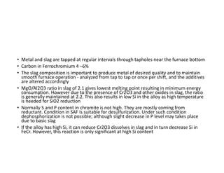
• Metal andslag are tapped at regular intervals through tapholes near the furnace bottom
• Carbon in Ferrochromium 4 –6%
• The slag composition is important to produce metal of desired quality and to maintain
smooth furnace operation - analyzed from tap to tap or once per shift, and the additives
are altered accordingly
• MgO/Al2O3 ratio in slag of 2.1 gives lowest melting point resulting in minimum energy
consumption. However due to the presence of Cr2O3 and other oxides in slag, the ratio
is generally maintained at 2.2. This also results in low Si in the alloy as high temperature
is needed for SiO2 reduction
• Normally S and P content in chromite is not high. They are mostly coming from
reductant. Condition in SAF is suitable for desulfurization. Under such condition
dephosphorization is not possible; although slight decrease in P level may takes place
due to basic slag
• If the alloy has high Si, it can reduce Cr2O3 dissolves in slag and in turn decrease Si in
FeCr. However, this reaction is only significant at high Si content
30.
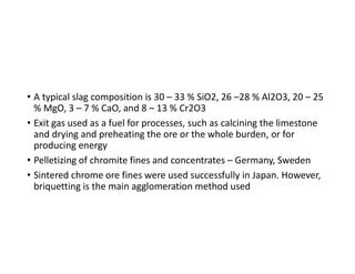
• A typicalslag composition is 30 – 33 % SiO2, 26 –28 % Al2O3, 20 – 25
% MgO, 3 – 7 % CaO, and 8 – 13 % Cr2O3
• Exit gas used as a fuel for processes, such as calcining the limestone
and drying and preheating the ore or the whole burden, or for
producing energy
• Pelletizing of chromite fines and concentrates – Germany, Sweden
• Sintered chrome ore fines were used successfully in Japan. However,
briquetting is the main agglomeration method used
31.
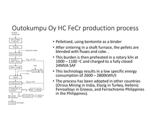
Outokumpu Oy HCFeCr production process
• Pelletized, using bentonite as a binder
• After sintering in a shaft furnace, the pellets are
blended with fluxes and coke. .
• This burden is then preheated in a rotary kiln at
1000 – 1100 ◦C and charged to a fully closed
24MVA SAF
• This technology results in a low specific energy
consumption of 2600 – 2800kWh/t
• The process has been adopted in other countries
(Orissa Mining in India, Elazig in Turkey, Hellenic
Ferroalloys in Greece, and Ferrochrome Philippines
in the Philippines).
32.
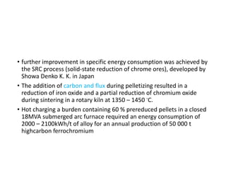
• further improvementin specific energy consumption was achieved by
the SRC process (solid-state reduction of chrome ores), developed by
Showa Denko K. K. in Japan
• The addition of carbon and flux during pelletizing resulted in a
reduction of iron oxide and a partial reduction of chromium oxide
during sintering in a rotary kiln at 1350 – 1450 ◦C.
• Hot charging a burden containing 60 % prereduced pellets in a closed
18MVA submerged arc furnace required an energy consumption of
2000 – 2100kWh/t of alloy for an annual production of 50 000 t
highcarbon ferrochromium
33.
• A newprocess for producing ferrochromium with 5 % C and <1 % Si
from unagglomerated chromite fines in a transferred arc plasma
furnace - developed by Tetronics Research & Development
• Commercialization of this process has been accomplished in South
Africa, where a 10.8MVA plasma furnace has been built
34.
MC FeCr production
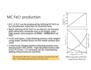
•0.5 – 4 % C can be produced by refining HC FeCr or
by silicothermic reduction of chromite ores
• Batch refining of HC FeCr in an electric arc furnace
with refractory chromite ores is no longer used -
high power consumption of 8000 – 9000kWh/t of
FeCr
• In US and Japan, a top-blowing process with oxygen
using water-cooled lances to the metal surface was
used
• In Germany, Oxygen bottom-blowing process was
introduced in the 1970s - high decarburization rate
of 0.3 % C/min – Cr recovery can be improved by
adding silicochromium and lime
OBM-oxygen blow of HC FeCr
oxygen bottom Maxh¨utte
The demand for MC FeCr is small compared to demand for the HC
FeCr , the decarburization processes are rarely used
35.
Low C FeCrproduction
• LC- or MC- FeCr can be produced by using HC-FeCr as rawmaterial
• Chromite addition: [Fe-Cr-C] + (FeO.Cr2O3) [Fe-Cr] + CO
• By oxygen: [Fe-Cr-C] + O2 [Fe-Cr] + CO
• LC-FeCr can also be produced
• by oxidation of FeCrSi melt with chromite: [Fe-Cr-Si] + (FeO.Cr2O3) [Fe-Cr] + SiO2
• As well as reduction of chromite with Si (FeSi):
[Fe+Si] + (FeO.Cr2O3) [Fe-Cr] + SiO2
• LC-FeCr is also produced by Al reduction
• However, reduction by Al and Si results in production of Al2O3 and SiO2.
They dissolves slag and reduces the activity of Cr2O3 in slag and making
reduction of Cr2O3 more difficult. To compensate this lime must be added
36.
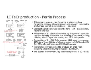
LC FeCr production- Perrin Process
• This process requires two furnaces: a submerged arc
furnace to produce silicochromium and an open-top electric
arc furnace to melt a chromite ore – lime slag
• Segregating ladle allowed to settle for 1 – 2 h - dissolved SiC
floats to the top
• Production of 1 t of silicochromium by this process typically
requires 1450 kg of chrome ore, 1500 kg of quartzite, 870 kg
of coke, 32 – 35 kg of electrodes, and 7700 kWh power
• Production of 1 t of LC FeCr requires 1440 kg of chrome ore,
1250 kg of lime, 660 kg of silicochromium (45 % Si and 40 %
Cr), 22 kg of electrodes, and 3200kW h power
• the total energy consumed to produce 1 t of LC FeCr,
including silicochromium production - 8200kWh.
• The overall recovery of Cr by the Perrin process is 90 – 92 %
20 – 25 % Si, 60 – 55 %
Cr, and 0.05 – 0.03%C
40 – 45% Si, 45 – 40%
Cr, & 0.05 – 0.02%C
8 – 10 % Cr2O3
25 – 27 % Cr2O3, 7 – 8 % FeO, 2 – 3 %
SiO2, & 45 – 48 % CaO
~70 % Cr, <1.5 % Si,
and 0.02 – 0.05 % C)
37.
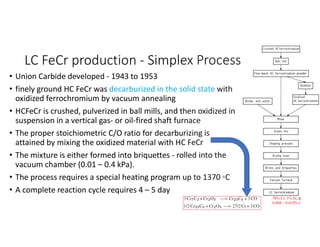
LC FeCr production- Simplex Process
• Union Carbide developed - 1943 to 1953
• finely ground HC FeCr was decarburized in the solid state with
oxidized ferrochromium by vacuum annealing
• HCFeCr is crushed, pulverized in ball mills, and then oxidized in
suspension in a vertical gas- or oil-fired shaft furnace
• The proper stoichiometric C/O ratio for decarburizing is
attained by mixing the oxidized material with HC FeCr
• The mixture is either formed into briquettes - rolled into the
vacuum chamber (0.01 – 0.4 kPa).
• The process requires a special heating program up to 1370 ◦C
• A complete reaction cycle requires 4 – 5 day
70% Cr, 1% Si, &
0.008 – 0.010% C


![Thermodynamics - Reduction by CO
• At 1873K, ∆Go = 91295J, reaction is not feasible
• Equilibrium constant, K at 1873, is 2.84 x 10-3 = pCO2/pCO assuming
activity of Cr2O3 and Cr are unity
• The CO utilisation efficiency(%)= [pCO2 /( pCO+ pCO2 )]eqbm x 100
=0.284%
• Similarly, at 1923K, CO utilization efficiency = 0.33%
• So CO is not an efficient reducing agent for Cr2O3 in reduction of
chromite](https://image.slidesharecdn.com/ferrochromeproduction-250519064350-1392f6d9/85/Ferrochrome-Production-Ferrochrome-Production-18-320.jpg)
![Low C FeCr production
• LC- or MC- FeCr can be produced by using HC-FeCr as rawmaterial
• Chromite addition: [Fe-Cr-C] + (FeO.Cr2O3) [Fe-Cr] + CO
• By oxygen: [Fe-Cr-C] + O2 [Fe-Cr] + CO
• LC-FeCr can also be produced
• by oxidation of FeCrSi melt with chromite: [Fe-Cr-Si] + (FeO.Cr2O3) [Fe-Cr] + SiO2
• As well as reduction of chromite with Si (FeSi):
[Fe+Si] + (FeO.Cr2O3) [Fe-Cr] + SiO2
• LC-FeCr is also produced by Al reduction
• However, reduction by Al and Si results in production of Al2O3 and SiO2.
They dissolves slag and reduces the activity of Cr2O3 in slag and making
reduction of Cr2O3 more difficult. To compensate this lime must be added](https://image.slidesharecdn.com/ferrochromeproduction-250519064350-1392f6d9/85/Ferrochrome-Production-Ferrochrome-Production-35-320.jpg)