Download to read offline
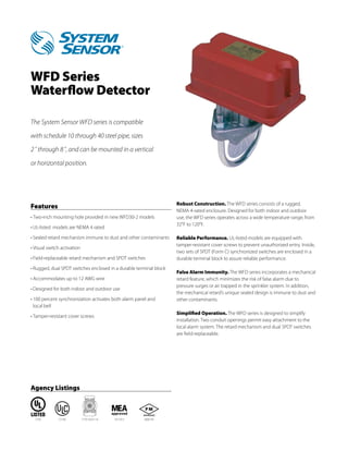


The WFD series waterflow detector from System Sensor can be installed on steel pipe from 2-8 inches in diameter and detects waterflow between 4-10 gallons per minute, featuring a field-adjustable mechanical retard mechanism, dual tamper-resistant switches, and a rugged NEMA 4-rated enclosure suitable for both indoor and outdoor use.


