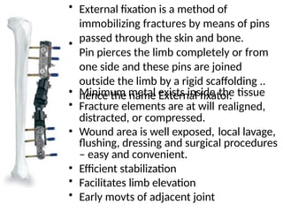
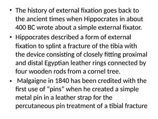
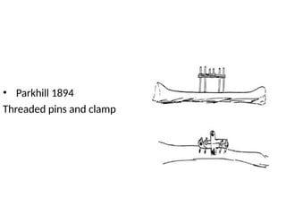
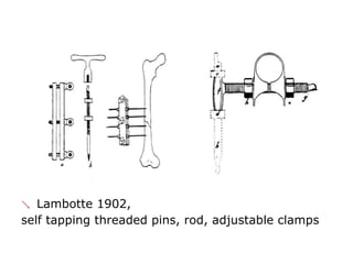
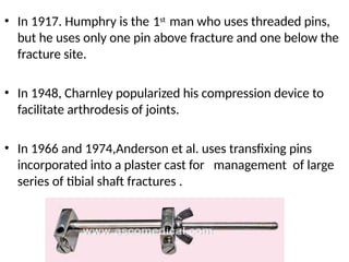
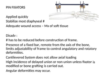
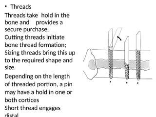
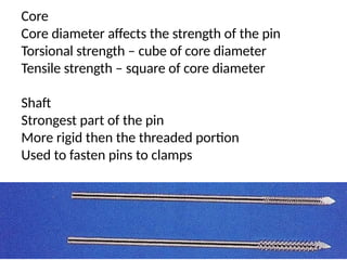
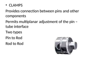
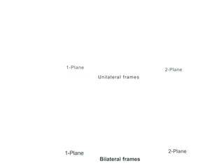
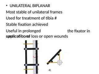
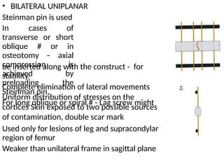
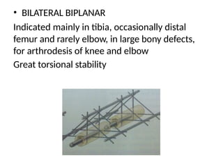
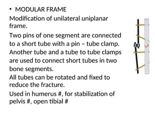
EXTERNAL
FIXATORS
• External fixation is a method of
immobilizing fractures by means of pins
passed through the skin and bone.
Pin pierces the limb completely or from
one side and these pins are joined
outside the limb by a rigid scaffolding ..
hence the name External fixator.
•
•
•
Minimum metal exists inside
Fracture elements are at will
distracted, or compressed.
the tissue
realigned,
• Wound area is well exposed, local lavage,
flushing, dressing and surgical procedures
– easy and convenient.
Efficient stabilization
Facilitates limb elevation
Early movts of adjacent joint
•
•
•
• The history of external fixation goes back to
the ancient times when Hippocrates in about
400 BC wrote about a simple external fixator.
Hippocrates described a form of external
fixation to splint a fracture of the tibia with
the device consisting of closely fitting proximal
and distal Egyptian leather rings connected by
four wooden rods from a cornel tree.
Malgaigne in 1840 has been credited with the
first use of “pins” when he created a simple
metal pin in a leather strap for the
percutaneous pin treatment of a tibial fracture
•
•
• Parkhill 1894
Threaded pins and clamp
 Lambotte 1902,
self tapping threaded pins, rod, adjustable clamps
• 1st
In 1917. Humphry is the man who uses threaded pins,
but he uses only one pin above fracture and one below the
fracture site.
• In 1948, Charnley popularized his compression device to
facilitate arthrodesis of joints.
• In 1966 and 1974,Anderson et al. uses transfixing pins
incorporated into a plaster cast for
series of tibial shaft fractures .
management of large
Aim of application
of External Fixator
is to achieve an
environment
conducive to
fracture and soft
tissue healing
Two main types
Pin fixators and
Ring fixators
,
PIN FIXATORS
Applied quickly
Stabilize most diaphyseal #
Adequate wound access – Mx of soft tissue
Disadv :
# has to be reduced before construction of frame.
Presence of a fixed bar, remote from the axis of the bone,
limits adjustability of frame to control angulatory and rotatory
deformities.
Cantilevered System does
High incidence of delayed
modified or bone grafting
not allow axial loading
union or non union unless fixator
is carried out.
is
Angular deformities may occur.
• RING FIXATORS
– Used in treatment of problems requiring complex
reconstruction
These frames replicate structure of long tubular bone like
exoskeleton.
Bone is stabilized by tensioned wires acting like elastic
band
Provides sufficient stability for most complicated
diaphyseal
fractures
Multiplane deformity correction can be achieved
Excellent for Progressive deformity correction, limb
lengthening and Mx of non union
–
–
–
–
–
–
–
–
–
–
Disadvantages :
Heavy, cumbersome
Time consuming procedure to plan and construct
Poor access to soft tissues
Risk of neurovascular damage
• Components of Pin fixator
Bone screws or pins
Clamps
Connecting rods or tubes
Half pin
�
j
j
lSteinmann pin
• Pin – Schanz screw or half pin
It has threads at one end and a rounded
3 mm to 6 mm diameter
Stabilizing hold on bone segment
Does not pass much beyond far cortex
tip at the other.
Modified cortical screw but the core diameter is slightly larger
than the corresponding cortical screw (3.4 mm instead of
3mm for a 4.5mm screw)
Torsional and bending strength increases
Steinman Pin. Available in 3, 4 and 5mm
Pin is described under 4 heading
Tip, Thread, Core and Shaft
Tip
Triangular tip cuts its own threads in the bone.
Pilot hole is drilled before inserting the pin.
A variety of pin tips are in use
• Threads
Threads take hold in the
bone and provides a
secure purchase.
Cutting threads initiate
bone thread formation;
Sizing threads bring this up
to the required shape and
size.
Depending on the length
of threaded portion, a pin
may have a hold in one or
both cortices
Short thread engages
Core
Core diameter affects the strength of the pin
Torsional strength – cube of core diameter
Tensile strength – square of core diameter
Shaft
Strongest part of the pin
More rigid then the threaded portion
Used to fasten pins to clamps
• CLAMPS
Provides connection between pins
components
and other
Permits multiplanar
tube interface
Two types
Pin to Rod
Rod to Rod
adjustment of the pin –
1-Plane 2-Plane
Unilateral frames
2-Plane
1-Plane
Biiaterai frames
• UNILATERAL UNIPLANAR
Simple to construct
Stiffness in sagittal plane is higher
Fewer skin entry holes – less
chances of infection, less scars
Pins applied in safe corridors
Sufficient stability is achieved
Reduction has to be done before
frame is complete
• UNILATERAL BIPLANAR
Most stable of unilateral frames
Used for treatment of tibia #
Stable fixation achieved
Useful in prolonged
application of
the fixator in
cases of bone loss or open wounds
• BILATERAL UNIPLANAR
Steinman pin is used
In cases of
transverse or short
oblique # or in
osteotomy – axial
compression is
achieved by
preloading the
Steinman pin.
For long oblique or spiral # - Lag screw might
be inserted along with the construct -
stability.
for
Complete elimination of lateral movements
Uniform distribution of stresses on the
cortices Skin exposed to two possible sources
of contamination, double scar mark
Used only for lesions of leg and supracondylar
region of femur
Weaker than unilateral frame in sagittal plane
• BILATERAL BIPLANAR
Indicated mainly in tibia, occasionally distal
femur and rarely elbow, in large bony defects,
for arthrodesis of knee and elbow
Great torsional stability
• MODULAR FRAME
Modification of unilateral uniplanar
frame.
Two pins of one segment are connected
to a short tube with a pin – tube clamp.
Another tube and a tube to tube clamps
are used to connect short tubes in two
bone segments.
All tubes can be rotated and fixed to
reduce the fracture.
Used in humerus #, for stabilization of
pelvis #, open tibial #
Modular frames - advantages
•
•
Total pin placement freedom.
Increased fracture reduction
possibility.
•
•
•
Secure fixation.
Easy dynarnizati n.
Quick pin
rernova l.
Applicable
addition or
• in segmental
fracture and joint injuries. ·
• Stable for bone segment
transportation.
• Important factors affecting stiffness :
Number of pins used
more number of pins – more stability
2 pin / segment for tibia and 3 for femur
pins closer to # - more rigid
more pin to pin distance in a segment – more
is the bending stiffness
pin angled at 90 degree – increases torsional stiffness
Pin diameter
4.5mm
3.5mm
2.5mm
to 5.5mm for tibia and femur,
for radius ulna and
for metacarpals or metatarsals
More the diameter – more is the stiffness
Distance between the bone and the connecting
rod
Closer the pin clamps can be to the pin –
bone interface – more rigid fixation
Optimal distance – 4 cms
2 rods increases the stiffness (Instead
Stiffness of the connecting rod
of 1)
Pin clamp interface
Slippage of clamp decreases stiffness
Periodic tightening
Number
and
orientation
of sidebars Clamp
type
Clamp
P
.in
separati
.
.
Sidebar/
bone
separatio
n
distance
Type
and
number
Span on Pin
within fracture
com onent of pins
Bone Bone
Pin separation
component
across
fracture
• Pin – Bone Interface
There is a race between increasing load carrying capacity
of a healing bone and failure of pin bone interface
Stress reducing factors at Pin Bone
Pin
Large diameter
High modulus material
Multiple pin cluster
Reduced Span
Preloading
Fixator
2 plane fixation construct
Patient
Reduced weight bearing
interface :
• Preloading :
Preload is a static force of sufficient magnitude applied
an implant to overcome all dynamic and muscular
contracture forces and to maintain uninterrupted pin
bone contact.
Lack of tension – leads to micro motion – leads to pin
loosening-
Osteoclast initiate bone resorption at periosteal and
endosteal surfaces
to
Radial preloading – best method of preloading, achieved
by inserting a pin which is larger in diameter than the pre-
drilled hole – a designed misfit
Optimal misfit is 0.1 mm. Not more than 0.3mm
Preseot status
• E,..ernal fixator not a 'F.. irst and final' (PDFC) technique in
a rure treatment
LX ellent short-term stabilizer in open vound, poor soft
tissue
condition and infection
Replaced by definitive implant when situation improves
Concentric limb segments poorly tolerate fixator pins:
early removal recommended
Eccentric limb segments fairly tolerate fixator pins: potential
for long term retention
B
-ilateral uni and biplanar arrangements are seldom used
•
•
•
•
•
•
•
•
Unilateral uni and biplanar constructs are occasionally
used
Modular frames are practical and preferred
r
-
fa
-
ce
-
is
-
the
-
w
-
ea
-
k l
-
ink
-
: deterrent for long
term
P
-in-bone
�in
-
te
- tion
-
ica
appl
• Pin fixator exceptionally used for segment
PROF. GABRIEL ABRAMOVITCH ILIZAROV
(1921-1992)
History
Professor Gavril Abramovich
Ilizarov was born in the
Caucasus, in the Soviet Union in 1921.
•
• He was sent, without much orthopedic training, to look
after injured Russian soldiers in Kurgan,Siberia in the
1950s. With no equipment he was confronted with
crippling conditions of unhealed, infected, and malaligned
fractures.
• With the help of the local bicycle shop he devised ring
external fixators tensioned like the spokes of a bicycle.
this equipment he achieved healing, realignment and
lengthening to a degree unheard of elsewhere.
With
• His Ilizarov apparatus is still used today as one of the
distraction osteogenesis methods.
RING FIXATORS
Main components
Rings
Wires
Bolts and buckles
Pins
Pin clamps
: Standard elements used to correct skeletal deformity
Secondary
Rods
Plates
Supports
Posts
Hinges
Washer
Sockets
Bolts
Nuts
components : necessary for assembly of fixator
RINGS
Flat surface and
multiple holes –
principal component
Provides strong support
for the frame, designed
to bear high stresses of
the tensioned wire
Internal diameter of
ring measures from 80
to
240 mm
Complete set has 12
•
•
It has half ring and full rings
Full ring has more holes than
rings
Half ring has 18 to 28 holes –
of 8mm diameter
two connected half
• 4mm apart and are
•
•
•
Five-eighths ring facilitates joint motion
Deployed near knee and elbow joint
Used in middle of regular frame to provide
for soft tissue
Weaker than full ring
access
•
Half ring with
curved ends
• It is modified 5/8
ring with ends
curved outwards
Configuration
fits deltoid area
of the shoulder
•
Arches
• Used in femoral
trochanteric
area and
shoulder joint
Available as 90
and 120 degree
•
Bolts and Nuts
•
•
Used to fasten various parts together
Bolt has hexagonal head of 10 mm and a
threaded
shaft of 6mmdiameter , pitch is 1mm
10, 16 and 30 mm long
Nuts have a diameter of 6mm and comes in 6mm,
5mm and 3mm height
1mm pitch of inside thread
Turn of a nut is used as a driving force in Ilizarov
1/4th turn 4 times a day is the rate of distraction –
compression
•
•
•
•
•
Rods
• 6mm thick stainless steel
threaded rod is the main
connector
Four equidistant rods connecting
2 neighbouring rings
More bending stiffness in a 4
rod construct
Can withstand high axial loading
Available in 10 lengths ranging
from 60 to 400mm
Pitch of the thread is 1mm
•
•
•
•
•
• A slotted cannulated
has 2x2mm slot
extending the length
20 threads acts as a
connecting rod and a
pulling device
rod
of
• K wires can be attached
by locking nuts
Partially threaded rods
along with telescopic
rods provides a more
stable assembly.
•
• Connection plates used to
reinforce ring fixator
Used to construct
oval rings for foot
and large frames for
correction of
angulation
•
• Threaded sockets are used
reinforced a threaded rod
Hollow and threaded from
inside
to
•
Supports, Posts and Half
hinges
Facilitate creation of construct
Placed at any location and
fixed at any angle
Support and posts bear
tremendous load
Half hinges have a supporting
base with 2 flat surfaces
matching 10mm wrench
Wire fixation bolts are of 2
types cannulated and slotted
• Washers fill space between
a part and the ring
Thickness ranges from
1.5mm to 4mm
•
• Wrenches used for
constructing frame
• Two methods
Complete frame construction before the
surgery or assemble frame piece by piece
Ring Position
Stationary ring is located on the
strongest widest part of the bone –
proximal end
5cms distal to the joint
Distal supporting ring located at distal
and
epimetaphysis 3- 5 cms away from joint line
Pusher puller ring is movable and is used for
distraction – compression, located 3 – 5 cms
distal to Fracture/Osteotomy/Non union
Reference Ring used as reference,
determines
the distribution of translating forces,
• Ring inclination is
perpendicular to the
bony segment
Space between skin
and ring : 3cms
•
• Closer the ring to the
bone fragment, more
stable is the fragment
during all movements
Wire and Schanz screw
•
•
•
•
•
Trocar Tip
Bayonet pointed
Olive
Interupted threaded
Full threaded
• 1.8mm for adults and
1.5mm for children
Wires are inserted
atleast 3 cms apart
Olive wires prevents
side to side shift
•
•
• Two wires crisscrossing at 90 degree has best
stability
Less angle permits displacement and parallel
wires allows free movement
•
Indications…
Limb lengthening
Deformity Correction.
Infected Non-unions.
Congenital Pseudarthrosis.
•
•
•
•
• Treatment of Joint Contractures e.g. resistant
congenital talipes euino varus, post burns
contractures, post-traumatic stiffness
Fixation of complex fractures
•
• Bone transport & Osteomyelitis (treatment of
missing bone in the limb, due to various causes)
Arthrodesis (fusion or joining of two bones
across
joint)
• a
THANK YOU

External fixator like pin fixators etc .pptx

  • 1.
  • 2.
    • External fixationis a method of immobilizing fractures by means of pins passed through the skin and bone. Pin pierces the limb completely or from one side and these pins are joined outside the limb by a rigid scaffolding .. hence the name External fixator. • • • Minimum metal exists inside Fracture elements are at will distracted, or compressed. the tissue realigned, • Wound area is well exposed, local lavage, flushing, dressing and surgical procedures – easy and convenient. Efficient stabilization Facilitates limb elevation Early movts of adjacent joint • • •
  • 3.
    • The historyof external fixation goes back to the ancient times when Hippocrates in about 400 BC wrote about a simple external fixator. Hippocrates described a form of external fixation to splint a fracture of the tibia with the device consisting of closely fitting proximal and distal Egyptian leather rings connected by four wooden rods from a cornel tree. Malgaigne in 1840 has been credited with the first use of “pins” when he created a simple metal pin in a leather strap for the percutaneous pin treatment of a tibial fracture • •
  • 4.
  • 5.
     Lambotte 1902, selftapping threaded pins, rod, adjustable clamps
  • 6.
    • 1st In 1917.Humphry is the man who uses threaded pins, but he uses only one pin above fracture and one below the fracture site. • In 1948, Charnley popularized his compression device to facilitate arthrodesis of joints. • In 1966 and 1974,Anderson et al. uses transfixing pins incorporated into a plaster cast for series of tibial shaft fractures . management of large
  • 7.
    Aim of application ofExternal Fixator is to achieve an environment conducive to fracture and soft tissue healing Two main types Pin fixators and Ring fixators ,
  • 8.
    PIN FIXATORS Applied quickly Stabilizemost diaphyseal # Adequate wound access – Mx of soft tissue Disadv : # has to be reduced before construction of frame. Presence of a fixed bar, remote from the axis of the bone, limits adjustability of frame to control angulatory and rotatory deformities. Cantilevered System does High incidence of delayed modified or bone grafting not allow axial loading union or non union unless fixator is carried out. is Angular deformities may occur.
  • 9.
    • RING FIXATORS –Used in treatment of problems requiring complex reconstruction These frames replicate structure of long tubular bone like exoskeleton. Bone is stabilized by tensioned wires acting like elastic band Provides sufficient stability for most complicated diaphyseal fractures Multiplane deformity correction can be achieved Excellent for Progressive deformity correction, limb lengthening and Mx of non union – – – – – – – – – – Disadvantages : Heavy, cumbersome Time consuming procedure to plan and construct Poor access to soft tissues Risk of neurovascular damage
  • 10.
    • Components ofPin fixator Bone screws or pins Clamps Connecting rods or tubes Half pin � j j lSteinmann pin
  • 11.
    • Pin –Schanz screw or half pin It has threads at one end and a rounded 3 mm to 6 mm diameter Stabilizing hold on bone segment Does not pass much beyond far cortex tip at the other. Modified cortical screw but the core diameter is slightly larger than the corresponding cortical screw (3.4 mm instead of 3mm for a 4.5mm screw) Torsional and bending strength increases Steinman Pin. Available in 3, 4 and 5mm
  • 12.
    Pin is describedunder 4 heading Tip, Thread, Core and Shaft Tip Triangular tip cuts its own threads in the bone. Pilot hole is drilled before inserting the pin. A variety of pin tips are in use
  • 13.
    • Threads Threads takehold in the bone and provides a secure purchase. Cutting threads initiate bone thread formation; Sizing threads bring this up to the required shape and size. Depending on the length of threaded portion, a pin may have a hold in one or both cortices Short thread engages
  • 14.
    Core Core diameter affectsthe strength of the pin Torsional strength – cube of core diameter Tensile strength – square of core diameter Shaft Strongest part of the pin More rigid then the threaded portion Used to fasten pins to clamps
  • 15.
    • CLAMPS Provides connectionbetween pins components and other Permits multiplanar tube interface Two types Pin to Rod Rod to Rod adjustment of the pin –
  • 16.
  • 17.
    • UNILATERAL UNIPLANAR Simpleto construct Stiffness in sagittal plane is higher Fewer skin entry holes – less chances of infection, less scars Pins applied in safe corridors Sufficient stability is achieved Reduction has to be done before frame is complete
  • 18.
    • UNILATERAL BIPLANAR Moststable of unilateral frames Used for treatment of tibia # Stable fixation achieved Useful in prolonged application of the fixator in cases of bone loss or open wounds
  • 19.
    • BILATERAL UNIPLANAR Steinmanpin is used In cases of transverse or short oblique # or in osteotomy – axial compression is achieved by preloading the Steinman pin. For long oblique or spiral # - Lag screw might be inserted along with the construct - stability. for Complete elimination of lateral movements Uniform distribution of stresses on the cortices Skin exposed to two possible sources of contamination, double scar mark Used only for lesions of leg and supracondylar region of femur Weaker than unilateral frame in sagittal plane
  • 20.
    • BILATERAL BIPLANAR Indicatedmainly in tibia, occasionally distal femur and rarely elbow, in large bony defects, for arthrodesis of knee and elbow Great torsional stability
  • 21.
    • MODULAR FRAME Modificationof unilateral uniplanar frame. Two pins of one segment are connected to a short tube with a pin – tube clamp. Another tube and a tube to tube clamps are used to connect short tubes in two bone segments. All tubes can be rotated and fixed to reduce the fracture. Used in humerus #, for stabilization of pelvis #, open tibial #
  • 22.
    Modular frames -advantages • • Total pin placement freedom. Increased fracture reduction possibility. • • • Secure fixation. Easy dynarnizati n. Quick pin rernova l. Applicable addition or • in segmental fracture and joint injuries. · • Stable for bone segment transportation.
  • 23.
    • Important factorsaffecting stiffness : Number of pins used more number of pins – more stability 2 pin / segment for tibia and 3 for femur pins closer to # - more rigid more pin to pin distance in a segment – more is the bending stiffness pin angled at 90 degree – increases torsional stiffness Pin diameter 4.5mm 3.5mm 2.5mm to 5.5mm for tibia and femur, for radius ulna and for metacarpals or metatarsals More the diameter – more is the stiffness
  • 24.
    Distance between thebone and the connecting rod Closer the pin clamps can be to the pin – bone interface – more rigid fixation Optimal distance – 4 cms 2 rods increases the stiffness (Instead Stiffness of the connecting rod of 1) Pin clamp interface Slippage of clamp decreases stiffness Periodic tightening
  • 25.
    Number and orientation of sidebars Clamp type Clamp P .in separati . . Sidebar/ bone separatio n distance Type and number Spanon Pin within fracture com onent of pins Bone Bone Pin separation component across fracture
  • 26.
    • Pin –Bone Interface There is a race between increasing load carrying capacity of a healing bone and failure of pin bone interface Stress reducing factors at Pin Bone Pin Large diameter High modulus material Multiple pin cluster Reduced Span Preloading Fixator 2 plane fixation construct Patient Reduced weight bearing interface :
  • 27.
    • Preloading : Preloadis a static force of sufficient magnitude applied an implant to overcome all dynamic and muscular contracture forces and to maintain uninterrupted pin bone contact. Lack of tension – leads to micro motion – leads to pin loosening- Osteoclast initiate bone resorption at periosteal and endosteal surfaces to Radial preloading – best method of preloading, achieved by inserting a pin which is larger in diameter than the pre- drilled hole – a designed misfit Optimal misfit is 0.1 mm. Not more than 0.3mm
  • 29.
    Preseot status • E,..ernalfixator not a 'F.. irst and final' (PDFC) technique in a rure treatment LX ellent short-term stabilizer in open vound, poor soft tissue condition and infection Replaced by definitive implant when situation improves Concentric limb segments poorly tolerate fixator pins: early removal recommended Eccentric limb segments fairly tolerate fixator pins: potential for long term retention B -ilateral uni and biplanar arrangements are seldom used • • • • • • • • Unilateral uni and biplanar constructs are occasionally used Modular frames are practical and preferred r - fa - ce - is - the - w - ea - k l - ink - : deterrent for long term P -in-bone �in - te - tion - ica appl • Pin fixator exceptionally used for segment
  • 30.
    PROF. GABRIEL ABRAMOVITCHILIZAROV (1921-1992)
  • 31.
    History Professor Gavril Abramovich Ilizarovwas born in the Caucasus, in the Soviet Union in 1921. • • He was sent, without much orthopedic training, to look after injured Russian soldiers in Kurgan,Siberia in the 1950s. With no equipment he was confronted with crippling conditions of unhealed, infected, and malaligned fractures. • With the help of the local bicycle shop he devised ring external fixators tensioned like the spokes of a bicycle. this equipment he achieved healing, realignment and lengthening to a degree unheard of elsewhere. With • His Ilizarov apparatus is still used today as one of the distraction osteogenesis methods.
  • 32.
    RING FIXATORS Main components Rings Wires Boltsand buckles Pins Pin clamps : Standard elements used to correct skeletal deformity Secondary Rods Plates Supports Posts Hinges Washer Sockets Bolts Nuts components : necessary for assembly of fixator
  • 33.
    RINGS Flat surface and multipleholes – principal component Provides strong support for the frame, designed to bear high stresses of the tensioned wire Internal diameter of ring measures from 80 to 240 mm Complete set has 12
  • 34.
    • • It has halfring and full rings Full ring has more holes than rings Half ring has 18 to 28 holes – of 8mm diameter two connected half • 4mm apart and are
  • 35.
    • • • Five-eighths ring facilitatesjoint motion Deployed near knee and elbow joint Used in middle of regular frame to provide for soft tissue Weaker than full ring access •
  • 36.
    Half ring with curvedends • It is modified 5/8 ring with ends curved outwards Configuration fits deltoid area of the shoulder • Arches • Used in femoral trochanteric area and shoulder joint Available as 90 and 120 degree •
  • 37.
    Bolts and Nuts • • Usedto fasten various parts together Bolt has hexagonal head of 10 mm and a threaded shaft of 6mmdiameter , pitch is 1mm 10, 16 and 30 mm long Nuts have a diameter of 6mm and comes in 6mm, 5mm and 3mm height 1mm pitch of inside thread Turn of a nut is used as a driving force in Ilizarov 1/4th turn 4 times a day is the rate of distraction – compression • • • • •
  • 38.
    Rods • 6mm thickstainless steel threaded rod is the main connector Four equidistant rods connecting 2 neighbouring rings More bending stiffness in a 4 rod construct Can withstand high axial loading Available in 10 lengths ranging from 60 to 400mm Pitch of the thread is 1mm • • • • •
  • 39.
    • A slottedcannulated has 2x2mm slot extending the length 20 threads acts as a connecting rod and a pulling device rod of • K wires can be attached by locking nuts Partially threaded rods along with telescopic rods provides a more stable assembly. •
  • 40.
    • Connection platesused to reinforce ring fixator Used to construct oval rings for foot and large frames for correction of angulation • • Threaded sockets are used reinforced a threaded rod Hollow and threaded from inside to •
  • 41.
    Supports, Posts andHalf hinges Facilitate creation of construct Placed at any location and fixed at any angle Support and posts bear tremendous load Half hinges have a supporting base with 2 flat surfaces matching 10mm wrench Wire fixation bolts are of 2 types cannulated and slotted
  • 42.
    • Washers fillspace between a part and the ring Thickness ranges from 1.5mm to 4mm • • Wrenches used for constructing frame
  • 43.
    • Two methods Completeframe construction before the surgery or assemble frame piece by piece Ring Position Stationary ring is located on the strongest widest part of the bone – proximal end 5cms distal to the joint Distal supporting ring located at distal and epimetaphysis 3- 5 cms away from joint line Pusher puller ring is movable and is used for distraction – compression, located 3 – 5 cms distal to Fracture/Osteotomy/Non union Reference Ring used as reference, determines the distribution of translating forces,
  • 44.
    • Ring inclinationis perpendicular to the bony segment Space between skin and ring : 3cms • • Closer the ring to the bone fragment, more stable is the fragment during all movements
  • 45.
    Wire and Schanzscrew • • • • • Trocar Tip Bayonet pointed Olive Interupted threaded Full threaded • 1.8mm for adults and 1.5mm for children Wires are inserted atleast 3 cms apart Olive wires prevents side to side shift • •
  • 46.
    • Two wirescrisscrossing at 90 degree has best stability Less angle permits displacement and parallel wires allows free movement •
  • 48.
    Indications… Limb lengthening Deformity Correction. InfectedNon-unions. Congenital Pseudarthrosis. • • • • • Treatment of Joint Contractures e.g. resistant congenital talipes euino varus, post burns contractures, post-traumatic stiffness Fixation of complex fractures • • Bone transport & Osteomyelitis (treatment of missing bone in the limb, due to various causes) Arthrodesis (fusion or joining of two bones across joint) • a
  • 49.