Download to read offline

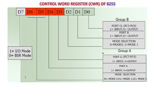
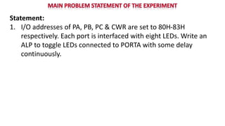
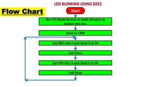
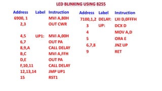
The document describes an experiment using an 8255 chip to blink LEDs connected to port A with a delay. The flow chart shows the program flow which initializes the I/O ports as outputs, writes 00H to port A, calls a delay subroutine, writes FFH to port A, calls the delay subroutine again, and loops continuously toggling the LEDs. The assembly language listing provides the code to initialize the I/O addresses, toggle the LEDs on port A, and implement a delay subroutine using a decrementing counter.