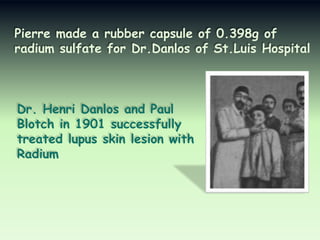
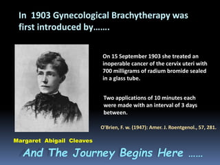
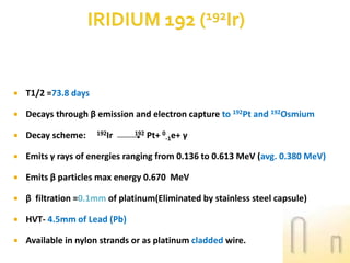
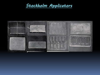
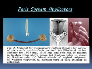
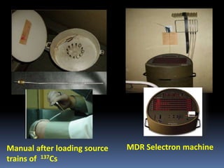
2. Down the memory lane……
1895: Discovery of
X-ray by Röntgen
1896: Discovery of Radioactivity by Becquerel
1898 : Discovery of Radium & Polonium by
Marie Curie and Pierre Curie
3. Pierre made a rubber capsule of 0.398g of
radium sulfate for Dr.Danlos of St.Luis Hospital
Dr. Henri Danlos and Paul
Blotch in 1901 successfully
treated lupus skin lesion with
Radium
4. “… there is no reason
why a tiny fragment of
radium sealed up in a
glass tube should not
be inserted into the
very heart of the
cancer; thus acting
directly upon the
diseased material.
A.G. Bell
Letter to Science, 1903
5. In 1903 Gynecological Brachytherapy was
first introduced by…….
On 15 September 1903 she treated an
inoperable cancer of the cervix uteri with
700 milligrams of radium bromide sealed
in a glass tube.
Two applications of 10 minutes each
were made with an interval of 3 days
between.
O'Brien, F. w. (1947): Amer. J. Roentgenol., 57, 281.
Margaret Abigail Cleaves
And The Journey Begins Here ……
6. The dose prescription was entirely empirical
Due to lack of –
Knowledge about the biological effects of radiation
on the normal tissues and the tumor
Understanding about the dose, dose distribution
and the duration of treatment
The Concept of Dosimetric system was introduced
Dosimetric systems denotes a set of rules taking into
account the source strengths ,geometry and method
of application in order to obtain suitable dose
distributions over the volume(s) to be treated.
8. Intracavitary systems
Interstitial systems
Edith Quimby
Quimby System
Gosta Forssell
Stockholm System
R. Paterson &
H.M Parker
Manchester
System
Claude
Regaud
Paris
System
M.C.Todd
Manchester
System
B .Pierquin &
A. Dutreix
Paris System
9. Stockholm system
Developed by Gosta Forssell by 1913 in Radiumhemmet , Stockholm
Later perfected by James Heyman and Hans Kottmeier
Fractionated (2--3 applications) delivered within about a month
Each application 20--30 hours
The amount of Radium was unequal in uterus (30--90 mg, in linear
tube) and in vagina (60--80 mg, in shielded silver or lead boxes)
Vaginal and uterine applicators were not fixed together
Total mg--hrs were usually 6500 to 7100 out of which 4500 mg were
in vagina.
10. Paris system
Developed by Claude Regaud by 1922 in Institute du Radium , Paris
2 applicators were used
a) Uterine applicator containing 13·33 + 13·33 + 6·66 mg. tubes of
radium loaded in tandem fashion.
b) Vaginal colpostat and cork together containing 33·32 mg. of radium.
Single application of 120 hrs.
Vaginal and uterine applicators were not fixed together.
Total dose given to both uterus and vagina was 30 m.c.d (4000 mg-hr)
11. When compared……
Uterine sources in both systems were arranged in a line
extending from the external os to nearly the top of the
uterine cavity.
Both systems preferred the longest possible intrauterine
tube to increase the dose to paracervical region and pelvic
region lymph nodes.
There was a limited use of external beam therapy in
Stockholm system, whereas Paris system used external
beam therapy before the implant.
12. Manchester system
Developed by M.C.Todd & W.J.Meredith in 1938 in Holt Radium
Institute ,Manchester
Later revised in 1953
Normal Tissue Tolerance :
“ paracervical triangle," ……… as roughly pyramidal in shape,
with its base resting on the lateral fornix and the apex curving
round with the anteverted uterus ”
13. Manchester system
“ point A is 2 cm. lateral to the central
canal of the uterus and 2 cm. from the
mucous membrane of the lateral fornix in
the axis of the uterus”
“ a secondary point, designated B, five
centimetres from the mid-line and on the
same level as Point A, is either in or near
enough the node to be used to give a
measure of the dose received by it.”
14. Initially used radium units were 6.66mg but later
changed to 2.5 mg each.
Two application 72hrs apart with 4 days in between
Dose of 8000R was delivered at pt A when radium used
alone for stage I/II ds
When radium was used along with deep-X ray therapy
for stage III or IV ds radium dose to pt A reduced to 6500R.
17. Single Plane Implant :
Rule 1: A fraction of the total activity is placed on the periphery of the
target volume with the remainder spread uniformly over the interior.
Implant Area Fraction on Periphery
< 25 cm2
2/3
25 – 100
1/2
> 100
1/3
Rule 2: The needles should be arranged in parallel rows 1 cm apart
with the ends crossed.
Rule 3: If the ends of the implant are uncrossed, the area should
reduced by 10 % for each uncrossed end for table reading purposes.
18. Cylindrical volume Implant :
1.
Total amount of Ra-226 is divided into 8 parts: 4 parts in the
belt, 2 parts for core, and each end 1 part.
2.
Needles should be parallel, spaced uniformly and not more
than 1 cm apart.
3.
7.5% is reduced from the volume for uncross end for table
reading purpose.
4.
The stated dose in 10% higher than min dose in the volume.
19. Quimby system
Developed at Memorial Hospital, NYC in 1930s and 1940s
by Edith Quimby for Ra sources
spaced R26 needles
• The Quimby system is characterized by a uniform distribution of
activity.
• Leads to higher dose in the central portion of the implant.
• Designed for interstitial implants using radium needles.
• Implantation Rules:
Lookup tables give number of mg-hr/1000 R in the center of the treatment
plane (top or bottom of a planar implant).
Stated dose is the maximum dose in the treatment plane.
Sources are spaced 1 cm apart and of same strength.
Ends are crossed.
20. Quimby based systems using
Ir-192 seeds in ribbon
• Kwan System ( Kwan et al. 1983)
• Tufts System ( Zwicker et al. 1985)
• Memorial System ( Anderson et al. 1986)
• Saw System ( Saw et al. 1988)
22. What is an Ideal Radionuclide?
• Easily available & Cost effective
• Gamma ray energy high enough to avoid increased energy
deposition in bone by PEE & low enough to minimise radiation
protection requirements
• Preferably monoenergetic: Optimum 300 KeV to 400 KeV
(max=600 kev)
• Absence of charged particle emission or it should be easily
screened (Beta energy as low as possible: filtration)
• Half life such that correction for decay during treatment is minimal
• Moderate gamma ray constant (determines activity & output) &
Godden ,1988
also determine shielding required.
23. What is an Ideal Radionuclide?
• No radioactive daughter
product; No gaseous disintegration
product to prevent physical damage to source and to avoid source
contamination
• High Specific Activity (Ci/gm) to allow fabrication of smaller
sources & to achieve higher output (adequate photon yield)
• Material available is insoluble & non-toxic form
• Sources can be made in different shapes & sizes
• Disposable without radiation hazard to environment
• Isotropic: same magnitude in all directions around the source
• No self attenuation
Godden ,1988
24. Radium
•
•
•
•
•
•
•
•
•
Earliest & once the most commonly used isotope
Naturally occuring ,extracted from Pitchblend ore
T ½ =1622 yrs
Disintegrates very slowly to hazardous radioactive gas Radon (Rn222)
Energy- ranging from 0.184 MeV - 2.45 MeV (avg.0.83Mev)
Some high energy β rays (max.3.26 Mev)
β filtration : 0.5 mm of platinum
Has been widely used for intracavitary,interstitial & mould applications
Radium sulfate/Ra chloride mixed with inert filler & loaded in cell(1cm
long &1mm in dia.made of 0.1-0.2 mm thick Gold foil).
Uranium
T1/2
Ra
1620Yrs
α
Rn
3.83days
α
RaA
3.05min
• Exposure rate constant : 8.25 R cm² /mg-h
α
RaB
26.8min
βγ
βγ
RaC
Pb
19.7min
Stable
25. TYPES OF RADIUM SOURCES
Shapes :
Uniform
o.33mg/cm
0.66mg/cm
Indian Club
0.66mg/cm
0.33mg/cm
0.66mg/cm
Dumb bell
Tube
Physical characters :
Wall thickness:
0.5mm of Pt+Ir alloy
Gold foil
:
0.1 mm thick
Cells
:
used for loading
Outer case(Pt+10%Ir)
Space for Ra+filler mixture
Eyelet hole
cells
26. Why Radium is not used now?
•Spectrum has > 8 photon energies ranging from 0.047- 2.45 MeV :
gives heterogeneous beam & non uniform dose distribution
• Low specific activity : 1 Ci/gm : requiring large diameter needles
• High gamma ray constant: requires more protection
• High energy: High radiation shielding will be required
• Rn 222 being the gaseous daughter product - threat of leaks from
long bent needles
• Storage & disposal of leaked sources a big problem
•Costly Ra source
27. CESIUM 137: ( Cs137)
• Recovered from fission products of U-235 made in Nuclear Reactor
• T1/2 : 30 yrs
1.8
• Relatively cheaper, extraction simple,
• Decay system :
137 Cs
55
137 Ba
56
+ 0-1e + γ
• No gaseous decay product, safer than Ra
• γ ray energy = 0.662 MeV
5mm
Active bead
(1.1mm dia.)
• β filtration – 0.5 mm stainless steel
• Available in tubes, needles, pellets.
• Replaced Ra in t/t of gynecologic cancers.
•
Exposure rate constant : 3.26 Rcm² /mCi-h
Stainless steel
Miniature cylindrical source
28. Manual afterloading system of Cs
Spiral spring
Source train consist of
flexible stainless steel holder
containing miniature source
separated by spherical steel spacers
1.8 mm in diameter. Sources and
spacers retained by a steel spring.
Min.cyl.sources
Spacer beads
Screw thread
Retaining spring
Source train
29.
T1/2 =73.8 days
Decays through β emission and electron capture to 192Pt and 192Osmium
Decay scheme:
Emits γ rays of energies ranging from 0.136 to 0.613 MeV (avg. 0.380 MeV)
Emits β particles max energy 0.670 MeV
β filtration =0.1mm of platinum(Eliminated by stainless steel capsule)
HVT- 4.5mm of Lead (Pb)
Available in nylon strands or as platinum cladded wire.
192Ir
192
Pt+ 0-1e+ γ
30. •Seeds are 3mm long & 0.5 mm in dia.
spaced with their centre 1cm apart.
•Internal core of 30%Ir +70%Pt
surrounded by 0.2 mm thick stainless
wall
Single Pin
192 Ir wire( coil form)
Hair Pin
Core diam: 0.1mm- 0.4mm
Sheath thickness : 0.1mm-0.4mm
Overall thickness: 0.3mm- 0.6mm
31.
Produced by neutron activation of stable isotope 59Co
Decay scheme: 6027Co
T1/2 = 5.26 yrs
Each disintegration produces 2 y rays of energy 1.33 & 1.17 MeV
(avg energy 1.25 MeV)
β energy= 0.318 MeV ;
HVL in Lead = 11 mm
High specific activity , miniaturized source can be made and used
in brachytherapy.
60 Ni+
0
28
-1 e
+y
32.
Modern techniques → Sources of higher Sp Activity →
Decreased source size compatible with remote
afterloading stepping source machines for HDR.
No need for frequent replacements
Cost effective
Low operating cost.
33. Ir-192 : A near ideal radioisotope
Compatible with after loading techniques
Ideal energy (0.3-0.4 MeV) – monoenergetic – more
radiobiological effect
Flexible & malleable – can be used in form of wires of any size
Energy is low – thinner shields required for radiation safety
β-energy is low – so lesser filtration required
Product (Pt192) not radioactive
Easily available , less costly
x Limitation
Short half life (73.8 days) so source has to be replaced every 3 months
36. Radium applicators for surface and intracavitary
applications, used by Danlos and later by Wickham.
37. Applicators
Applicators used to insert intracavitary sources in the
uterus and vagina included
Rubber catheters and ovoids developed by French researchers.
Metallic tandems and plaques designed in Sweden.
Thin rubber tandems and ovoids of the Manchester system.
Fletcher (1953) designed a preloadable colpostat, which
Suit et al. (1963) modified and made after loading.
38.
39. Types of Brachytherapy……
• Depending on source loading pattern:
– Preloaded: Inserting needles/tubes containing
radioactive material directly into the tumor
– After loaded: First, the non-radioactive
tubes inserted into tumor
• Manual afterloading: Sources manipulated into
applicator by means of forceps & hand-held tools
• Remote after
loading: consists of pneumatically
or motor-driven source transport system
42. Manchester System Applicators
Intrauterine applicator :
A thin rubber tube with a flange at the end, which is held by the spacer and packing
Intravaginal applicator :
Vaginal applicators are essentially modification of corks described by Regaud , in the
Paris technique.
Made of hard rubber, and bored along the axis to take 1 or more radium tubes of
actual length 2.2 cm., active length 1.5 cm.
The shape of the ovoid follows the distribution in three-dimensional space of the
isodose curves round a radium tube of 1 -5 cm. active length
Large ovoid : 3cm , Medium : 2.5 cm, Small : 2cm in shortest diameter
The ovoid pairs are separated at 1cm by a rubber made “Spacer” Or Kept in contact
by means of a “Washer”
43. Loose preloaded
system with
chances of slipping
of ovoids and hence
disturbed geometry
and creation of cold
and hot spots
leading to high
failure or increased
morbidity.
44. Photographs of original preloadable
Fletcher applicators
Pair of cylindrical “small”
ovoids (2 cm in diameter) with
inter-locking handles.
Plastic jackets of two
thicknesses are added to made
medium (‘2.5 cm in diameter)
and large (3 cm in diameter)
sizes.
The applicators have the same diameter as the Manchester ovoids but not the
shape of an isodose
Fletcher et al. Radiology 60:77-84, 1953
45. •In 1960-Ulrich K Henschke first described Manual afterloading
•In 1962-Walstram first described remote afterloading
(Based on ALARA principle – As Low As Reasonably Achievable)
•In 1964- First developed Remote afterloading device
Curietron prototype (1965)
Initial single channel remote
Afterloading machine 1962
Cobalt Ralston 1970
46. Fletcher afterloading colpostats
In 1958, Suit et al. developed the first afterloadable Fletcher colpostat
In 1978, Delclos et al. improved design of the afterloadable Fletcher colpostats
Fletcher
Suit
a. Fletcher-Suit
rectangular-handle model
b. Round-handle,
lighter model.
Delclos
48. Modern HDR Brachytherapy Machine
MicroSelectron
(Nucletron)
VariSource & GammaMed
(Varian).
HDR plus
(IBt Bebig)
49. PDR Brachytherapy
Series of short HDR
treatments ( 10 minute
pulse repeated at 1 hr
intervals)replacing the
Continuous LDR treatment
lasting several days.
Overall time remains same as LDR
Source strength : 1 Ci
ADVANTAGE:
•Radiobiologically nearer to LDR
•optimization possible
•Nursing care possible without radiation hazards
Nucletron
PDR
afterloader