Download to read offline


![CUSTOmER
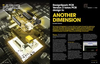
PROfIlE Power over Ethernet started
Q
out as a proprietary
technology developed
by network equipment POWER
uick OVER
vendors such as Cisco, to
deliver power to VoIP (Voice
EThERNET
over Internet Protocol)
phones without using
separate power supplies.
uestions
SImPlIfyING
Other manufacturers soon
realised the advantages
of sending DC power over
ThE EQUaTION
Key facts the network: especially,
Company Name Bytec Group cheaper cabling and higher
Year established 2007 data rates than alternative
Location Redhill. Surrey USb and aC powerline
Number of employees 30
technologies.
Key market Medical and rugged keyboards,
Displays and HMI
Website
Interviewee name
www.bytecmedical.co.uk
James Barr These are benefits not
only for IP
telephones, but also for security
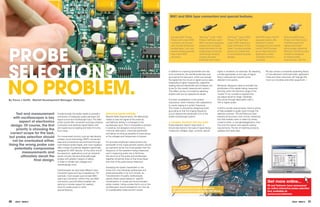
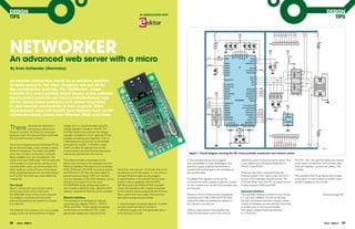
IEEE 802.3at
Updated in 2009, IEEE 802.3at uses phantom
power techniques to allow powered pairs
Interviewee position Senior Product Designer cameras with pan/ tilt/ zoom functions, to also carry data. This extends its use to
embedded computers, Ethernet 1000BASE-T, which uses all four cable pairs
switches, thin clients and even LCD for Gigabit/s data. In real-life applications, PoE
displays. Such diversity also brought the Plus or PoE+ is able to deliver 25.5W at 44V
What is your latest product? how do you gain new skills? need for standardisation. and up to 350mA down a standard Category
MediKey Mk2 Infection control keyboard Seminars and webcasts offer good opportunities for training 5 Cable using two twisted pairs. [Midspan
on specific activities (mostly relating to software), but also the IEEE 802.3af-2003 manufacturers such as Phihong have extended
What differentiates your products? everyday activity of ‘design’ uncovers new challenges which The original IEEE 802.3af-2003 standard this capability by delivering power through
High level of water ingress protection, rugged enclosure push us all to explore all avenues of reference media to solve defined the implementation of sending unused data pairs as well as the network
and multipoint gesture touchpad. a problem. power as well as data over Ethernet cabling. cables in use.]
Category 5 cables contain four twisted pairs,
What new technologies does your product employ? What RS service do you find most useful in your but only two are used for data transfer in either PoE support from RS
Anti-Microbial silver ion additive is included in the plastic and job and why? 10BASE-T or 100BASE-TX. This leaves two RS stocks many components to support PoE
rubber covers. Brand new ‘widescreen’ format touchpad. The fast delivery of goods is essential. When you discover you pairs available to carry DC current. Power is designs including ICs from Texas Instruments,
need something specific to complete a prototype you can most delivered to the end device (PD) either by PoE National Semiconductor, Linear Technology
how did you equip yourselves with knowledge often find it in RS online and have it the next day. enabled Ethernet switches (endspans) or by and STM Electronics. In addition, our range
of this new technology? figure 2. Typical PoE powered access point: injection from a midspan power supply. includes off-the-shelf solutions such as
We have a dedicated team of electronics engineers who What technology do you foresee having the biggest the access point’s PSU needs are supplied via
powered device (PD) interfaces from Murata,
routinely investigate new technologies to keep well impact on your next product? the Ethernet cable using the PoE splitter seen
PoE enabled microcontrollers from Olimex
informed on new innovations. There is always evolution within our designs, sourcing of on the side of the Ethernet wall socket
and Phihong’s range of midspan injectors
electronic and mechanical components and having access to a and splitters.
Give an example of the impact one of your products wide selection to choose from in one place is very important.
has on, or the benefits it provides to, the end user. For example new switches which have better functionality or a RJ-45 Input RJ-45 Output
Sold predominantly to the healthcare industry our Medi-Key smaller form factor than previously help to give our designers the (Data Only) (Data & Power)
keyboard takes on board years of research gained through sales freedom to explore new options.
into the medical sector. As a HMI (Human Machine Interface) Pin Symbol Description Symbol Description To learn more about PoE see the
solution it incorporates a touchpad and full size keyboard but What is the biggest threat to your business? 1 RX+ Data Receive(+) RX+ Data Receive(+) Design Tips section in this issue
with the crucial advantage of being able to be ‘deep cleaned’ Many sales are into funded organisations. There is always the 2 RX- Data Receive(-) RX- Data Receive(-) on Pages (28,29 and 30) for an
(submerged in soapy water), essential to help prevent cross worry that budget cuts will affect our customers’ spending power. 3 TX+ Data Transmit(+) TX+ Data Transmit(+) Elektor reference design.
contamination between different users and spread of 4 NC No Connection +Vdc DC power(+)
contagious diseases. Where do you see your industry in 5 years?
5 NC No Connection +Vdc DC power(+)
The medical industry on the whole tends to be fairly
how do you learn about new technologies? constant. It is in the most part an industry (alongside military) 6 TX- Data Transmit(-) TX- Data Transmit(-)
We regularly monitor trade press, websites and have a network of which weathers recessions well and has good opportunities 7 NC No Connection -Vdc DC power(-) Get more online...
industry contacts who offer advice and keep us updated on new to grow as technology becomes less expensive or more 8 NC No Connection -Vdc DC power(-)
Simply go to rswww.com
technologies. mature over time.
and search for “PoE”.
figure 1. Example configuration with an original data-only versus a PoE solution
18 eTech - ISSUE 6 eTech - ISSUE 6 19](https://image.slidesharecdn.com/uketech6-110421043601-phpapp02/85/eTech-Magazine-Issue-6-11-320.jpg)

![DESIGN DESIGN
REVIEW REVIEW
CONNECTING
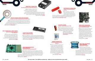
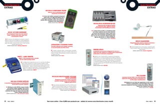
Design considerations for the Programming the Digital Potentiometers Resources
anti-aliasing filter The potentiometers are programmed from an [1] Software drivers for the AN16 module
The frequency plots in Fig.1 provide a I2C serial bus with two allocated to each filter together with full code listings of sample
ThE aNalOGUE
graphical representation of aliasing. In this controlling the resistive components which set programs can be downloaded from the EDP
example we are going to sample a signal the cut-off frequency. [1] Advantage is taken Design Centre on the DesignSpark website at:
which has a maximum frequency component of a simplification of the Sallen-Key filter which http://www.designspark.com/design-centre.
of fmax (the band in green) using a sampling occurs when the two resistances and two
WORlD TO
frequency of fs. The plot on the left shows capacitances are in the ratio 2 to 1. [2] [2] Analysis of the Sallen-Key Architecture, TI
all the new frequencies present in the non- Application Report, SLOA024B.
aliased sampled signal. Note that we now
RS EDP
have new bands of frequencies (in blue) each
with a width of 2 x fmax and centred on the Share your views on this article
sampling frequency ƒs and its harmonics. This at www.designspark.com
is a correctly sampled signal because fs > 2 x
fmax. By contrast the plot on the right shows
extensive aliasing where the various bands
overlap leading to the production of erroneous
frequencies in the green baseband. dB
analogue Input module: Setting up the anti-aliasing filter 0 2-Pole Filters, AN0 or AN1
The practical problem is that few ‘raw’ signals Roll-off = -40dB/decade
have a nice, clean fmax. In order to avoid
aliased components being produced, a low- -
Get the Specification pass anti-aliasing filter needs to be placed in 20
4-Pole Filter, AN0 + AN1
circuit before the ADC. Roll-off = -80dB/decade
Before the considering the analogue input f > 2f : No aliasing f < 2f : aliasing
S max S max
to a digital system, the designer must have -
available a certain amount of numerical data: Fig.2 shows the trade-off between sampling 40
Signal Power Signal Power rate and the order of the low-pass filter. The
• The maximum frequency component of Aliased Frequencies designer can massively over-sample and then -
the analogue signal use a simple low-order filter or select a lower 60
rate and then be faced with the need for a
• The Dynamic Range of the analogue complex multi-pole type. However the ability
signal (ratio of the maximum to the of the DSP device to process the algorithm
minimum input signal level) between consecutive samples must be 100 1000 10000 100000 1000000 f Hz
• The required Signal-to-Noise ratio of the considered before the sampling rate is set. Filter cut-off range
digitized signal It can save a lot of trouble later if the DSP AN0 or AN1
program is tested and timed on a suitable
fig. 3 frequency response of digitally-controlled filters on aN0 and aN1
development system before the sampling rate
The first point is what concerns us here when is fixed and the filter designed.
deciding on the cut-off frequency of the input fig.1 aliasing
analogue low-pass-filter. anti-aliasing filters on the analogue
Input module (EDP-am-aN16)
Signal Power
Decide on the sampling rate Sampling rate mUCh greater than Nyquist Sallen-Key filters are used on the Analogue
The sampling rate is set according to the Input module which provides filter circuits for
Nyquist criterion which states that it must be up to 16 input channels. Eight have simple
Lower Order, shallow roll-off LPF required Rf = 6772556u/Fcut_off; /* Calculate filter R2 resistor value */
at least twice that of the maximum frequency passive 1-pole filters, six have fixed cut-off R2_Pot = 12000u*Rf/(12000u-Rf); /* Digital pot in parallel with 12k resistor */
component present in the analogue signal. This (12kHz) 2-pole Sallen-Key filters with a roll-off R1_Pot = R2_Pot/2u; /* R1 resistor value = R2/2 */
ensures accurate reproduction of the signal, of -40dB/decade and two have 2-pole filters
but a much higher rate will ease the design whose cut-off frequency can be set by digital Set_resistance(1u,R1_Pot); /* Call AN16 driver and set Pot channel 1 */
of a vital circuit that precedes the ADC: potentiometers. These two filters on channels Set_resistance(2u,R2_Pot); /* Call AN16 driver and set Pot channel 2 */
the Anti-Aliasing filter. AN0 and AN1 can be cascaded by means of
Signal Power a solder-link to provide a single 4-pole filter on
AN0 with -80dB/decade roll-off. listing 1. C code for calculating the aN0 filter resistance values
Sampling rate JUST greater than Nyquist
High Order, steep roll-off LPF required
Get more online...
fig.2 Designing the anti-aliasing filter: Cut-off and Roll-off See the latest on EDP at www.designspark.com/theme/rs-edp
24 eTech - ISSUE 6 eTech - ISSUE 6 25](https://image.slidesharecdn.com/uketech6-110421043601-phpapp02/85/eTech-Magazine-Issue-6-14-320.jpg)

![DESIGN knitter-switch Multi-Function
TIPS number one in switches Tact Switches
Switches for all Applications
< Continued from page 29 5 Million Switches in Stock
Worldwide Support rswww.com/knitter-switch
Communications be extended and modified as long as it is Using the module
Pins TX and RX are connected to a UART that only used in Microchip devices. It contains a A simple way to find out what IP address has
can support speeds of up to 115200 baud. rich collection of hardware drivers, low-level been acquired is to use Bonjour, a program
An SPI interface is available on the pins with protocol implementations (ARP IP TCP and so
, , developed by Apple which is now also available Toggle Switches Tact Switches
labels starting ‘SPI’. The interface can operate on) and a couple of important application-level for Windows (most simply installed as a
in master mode or in slave. protocol implementations such as DHCP and
HTTP The simple MPFS file system is also
.
browser plug-in, for example for Firefox [2]).
Rotary Coded Dual-in-line
Software library
A ‘stack’ is a collection of software
included to allow storage of web page source
data. Example applications, a bootloader, tools
Serial modes
When a suitable network connection is
Switches Switches
Slide Switches Micro Switches
implementations of protocols and drivers, and comprehensive documentation of all stack established with the serial server data can
usually arranged in a hierarchy of layers. At functions complete the package. be sent using TCP/IP to the unit. Further
the bottom end of the stack are the hardware details on the additional protocols required
drivers which are responsible for getting data application software for operation in this mode can be found in a
bits transferred onto the network wires. At the The module has an integrated bootloader that supplementary document downloadable knitter-switch
top end of the stack is a simple interface for
data exchange.
allows a new version of its firmware to be
uploaded over the Ethernet connection for
from the Elektor website.
Pushbutton knitter-switch UK Limited
Switches
Grove House, Lutyens Close,
installation at any time: suitable hex files are
Chineham Court, Basingstoke,
In theory, the layered protocol model makes available on the project’s web pages [1]. The
RG24 8AG, United Kingdom
it relatively easy to make modifications to one author developed the application software
layer (such as the hardware driver) without for the module using the MPLAB IDE. It is Rotary Switches Tel: +44 (0) 1256 338670
affecting the others. In practice however, written entirely in ANSI C and can be Fax: +44 (0) 1256 338671
Encoders
when implemented on a microcontroller, the compiled using the free version of the Email: ksuk@knitter-switch.com
hardware and the stack are very closely tied Microchip C18 compiler. www.knitter-switch.com
together, and lots of tricks need to be used to
keep memory usage low. Nevertheless, TCP/IP The application consists of three modules,
stack implementations are available for a wide called Main, Web and Appl. The bootloader
range of microcontroller families, often for free jumps directly to Main, where the TCP/IP stack,
and direct from the manufacturer. the EEPROM driver and the Appl module are
Microchip offers a TCP/IP stack for its PIC18, initialised. Then Appl and the TCP/IP stack Internet Links
PIC24, dsPIC and PIC32 microcontroller receive processing time alternately in an [1] www.elektor.com/100552
families written in ANSI C. It is free and can infinite loop. [2] www.bonjourfoxy.net
DesignSparkPCB
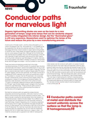
Component list
Resistors (SmD 0603) RS Stock No. Semiconductors RS Stock No
R101 = 1MΩ 678-9932 IC1= PIC18F67J60 (TQFP64), 400-766
R102 = 4.7kΩ 679-0484 IC2= 11AA02E48 (SOT23) 667-8034
R103 = 1kΩ 678-9875 TR1= 10/100Base-TX transformer,
NeW 3d vieWer
R104 = 2.26kΩ 679-0128
Halo N5 (SMD), PoE to IEEE 802.3af 615-4406 or 615-4434
R105,R106 = 560Ω 679-0541
R107–R110 = 49.9Ω (1%) 679-0459
miscellaneous RS Stock No.
reLeaSeS your
J1= 8+2+2 pin RJ45 socket, w. 2 integrated LEDs
(use integrated TR1)
Capacitors (SmD 0603): RS Stock No. JP1,JP2 = 10-pin SIL pinheader (lead pitch 0.1 in.) 681-3004
C101–C109= 100nF 391-246 Q101 = 25 MHz SMD quartz crystal, HC49UP case 671-9280
C110,C111= 33pF 616-9161 PCB, Elektor # 100552-11 [1]
CreaTiviTy
C112= 10µF 698-3239 http://be.eurocircuits.com/Offtheshelf/Offtheshelfdefault.aspxw
Inductors (SmD 0603): RS Stock No.
FE101 = 1k @ 100 MHz 367-4856
The World’s Most Powerful Free Schematic and
PCB Layout Tool is yours to download now
Get more online...
www.designspark.com Download your free copy at
www.designspark.com/pcb WIrED BY
30 eTech - ISSUE 6](https://image.slidesharecdn.com/uketech6-110421043601-phpapp02/85/eTech-Magazine-Issue-6-17-320.jpg)


The document discusses connectivity technologies and how they enable new functionality. It introduces several connectivity topics that are featured in the issue, including USB 3.0, ZigBee mesh networking, Power over Ethernet, and human-machine interfaces. The goal of RS Components is to help customers find the right connectivity solutions for their projects and provide components to support prototyping and production. An interactive iPad app has been created to deliver enhanced content for eTech magazine.


