Downloaded 39 times


!['i{ii;r-."
: : ;
laughinga t me". So no apologiesf or the useo f a light
bulb'in this design-
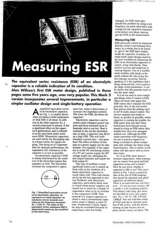
Operotion of the Oscillofor
Fig. 3 shows the Wien,bridge netwoik oscillator as
you probably won't have seen it drawn before. It.illus-trates
the situation at the peak of the positive-going
half cycle. The positive feedback network consists of
the series-paralleRl C (lead;lag) network: the negative
feedback loop consists of the preset Rf and'bulb Rin.
We'll consider the RC network first. At very high
frequencies the shunt capacitor in the lower arm of the
bridge will appear to be a short-circuit and there will
be no signal at the op-amp's + input. At very low fre-quencies
the series capacitor will appear to be open-circuit
and again there will be no input from the feed-back
network. At some point in between there will be
maximum output from the network. The frequency at
which this occurs is equal to ll(2nRC), which is called
the resonant frequency (fr) of the bridge network. At
' this point there is no phase shift across the bridge, and
the upper arm of the network has twice the impedance
of the lower arm, giving a transmission lgss of 1/3. To
overcome this loss and achieve the required stage gain
of unity, the closed-loop voltage gain (ACL), which is
set by thc ratio of Rf to Rin, must be three. The for-mula
for the closed-loop gain of a non-inverting
amplifieris ACL = M/Rin + 1, so Rf/Rin must be two
in order for ACL to equal three. , ....
At power up the negative feedback is low, because
the bulb is at its lowest resistance, and.the gain is
high. As,a rcsult oscillation begins immediately, aud
' the bulb is warmed by the current current flow. Within
a fraction of a second the resultant increase in its
resistance reduces the oscillator's output. It settles at
the level at which the bulb's resistance is half that of
the feedback resistor Rf. So the value.of Rf sets the
amplitude,of ,the"output.,Notet hat the bulb's thermal
delay means that it cannot follow oscillations at rela-tively
high frequencies. It.responds to the RMS.cur-
. rent,gnly, and phus lehavps,F a.n ordinary resistor. . i ;g
y. " { " '
- - b r ' . , i ] ; , t . r , f + ' i , . ' . . + , j r , ' , j : .
The Bulb ,: ' .:'.
. Although the Wien bridge oscillator is the accepted
statrdard'at frequencies up to say lMHz, the use of a
bulb for gain control, popular in the USA, has never
found favour on this side of the Atlantic. I think I.
know thc rcason for this., In most textbooks things
begin to get a bit vague iwhen it comes to the actual
type of light bulb to use.
It is often said that any low-yoltage, low-current
bulb can be used. This is not so. I have seen the fol-lowing
flawed reasoning in some books. Take a l2V,
50mA bulb-which has a resistance of l2Vl50mA =
240Q. The feedback resistor must be twice this, i.e.
480Q or a lk() preset. There's nothing wrong with
this value for the feedback resistor, but it won't work
with such a bulb. The point that's been missed is this:
the bulb must be operated at a current level that gives
a large change of resistance.
This occurs when the current is only a few mil-.
liamperes,a nd nowheren earb ulb incandescenceW. hat
we requirei s a bulb that hasa resistanceo f about 200f1
when cold. When the type of bulb normally specified is
used, the result is overloading of the op-amp, distor-tion,
heavyc urrentd rain and dependenceo n the supply
voltage for regulation rather than correct bulb opera-tion.
I didn't do what Hewlett did, which was to plot the
1/ characteristicos f variousb ulbs carefully. I simply
TELEVISIONM arch 1999
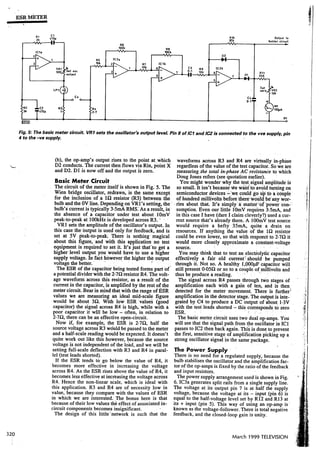
Fig. 1: Pr*ision rectifier circuit, (al with positive input, bl with negative
input. In (aJ the op-amp's orrtPttt goas as low as required to overcome the
forward voltage drop acrosli D'| and still satisfy Ohm's law as far as Bf and
R|n are concerned. D2.is off as the voltage at its anode is 2'6V le*s than
that at iE cathode. In (b) D.l is off, its cathode voftage being 0'6V higher
than its anode voltage. The conduction of D2 limits the positive o,ftptlt 8t
0.6V. This limiting factor speeds up the recovery of the op'amp when the
input goes positive again.
I ; : ' r . ; l ; : : i . . ' '
measured the resistauce of pulbs that I thought might
be'iuitable, and found that the cold resistance of a
28Y,24r.A hulb is l70Q-. fitis soemed to be about
right. When I tried it -,bingo! So when, in this con-nection,
you see "any low-voltage, 50mA or so bulb"
you can in future read "a28Y,24mA bulb". The oscil-lator,
will work a treat.
The Prbcision Rectifier
The final stage of the basic meteruses an op-amp as a
precision rectifier..Keeping to the type ofrepresenta-tion
we've used before, Fig. 4 shows its method of
operation.
With a conventional rectifier there's the drawback
that the signal must rise above the diode's forward-voltage
drop before conduction begins. This can be
overcome by the use of an op-amp in the circuit. At (a)
in Fig. 4 the input is positive and the output reduces
the voltage at the cathode of Dl. This enables the
input to carry on via Rf to the amplifier's output. As
in the case of the inverting amplifier circuit, the out-put
is again Vin x Rf/Rin. The diode's forward volt-age
drop, which is 0.6V with a silicon diode, is over-come
becauseth e op-amp'so utputg oesl ower by this
amount, satisfying Ohm's law as far as Rf and Rin are
concerned.
Point X is still held at earth potential by feedback
action from the output. D2 is off at this time, as the
voltage at its anode is lower than that at its cathode.
When the input goes negative however, as shown at
Yflt - 0v
D5UO
Vioa -lY
3 1 9](https://image.slidesharecdn.com/esr-capacitor-meter-project-141209080954-conversion-gate02/85/Esr-capacitor-meter-project-4-320.jpg)
![ESR METER
-
. . r . : : i i . i + r , . . . .
_:{:f '
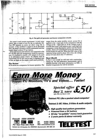
than it needs to be to.dccdmmodate the components.
There arc two reasons ifor this: First, so that it will slot
into the case that was selected, and secondly to allow
space for future upgrades. With this in mind the set-zero
control is offset to the right, allowing space for a modu-lar
preset shaft.
The batteries are securcd with self-adhesive Velcro.
It's a simple solution, and the Vrlcro will transfer sev-eral
times.
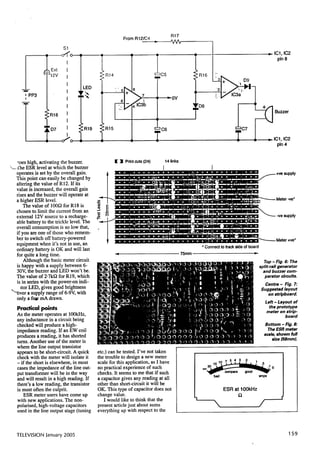
witli theWizard this meterdoes not dif-feientidte
between a $hort4ircuit capac.
itor and a really good one (with an ESR :
arc-und 0.050). Now although we all
kiiow ' that a short+ircuit electrolytic
capacitor is quite rare, it ciio'occur and
has caught me and others out. Allot of
time can be wasted when it occurs and is
missed. So I've been testing an addition
that gives an audible indication when a
short-circuit is present. A further refine-ment
is an auto power-off facility.
I've not included these extras at pre-sent
because I feel it best to present as
simple and economic a pdect as possi-ble
initially. But space has been left for
these additions.
Gomponenl Sources
I obtained most of the pans used in the
prototype from Maplin Electronics and
have included this company's part num-bers
in the componentsli st. The buzzer
and meter movement were obtained
from CPC. For correct operation of the
oscillator it's vital that Cl and C2 are
good-quality polystyrene capacitors.
TELEVISIOANp r i l 1999
: . ' . , .
Apart from the bulb, the sp&ifrcation 6f ttre other com-ponents
is not critical.
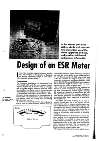
The Mefer Scole
The geometry of the meterls scale (see'Fig. 7) is dictar
ed by the relative values of R3 and R4. If the value of
R4 was'inbreased to say 10O, this would be the mid-scale
reading and R3, being low in comparison, would
hav,e less effecl Say a capacitorwith -aerESR iriil!
of l0O is
connected. Half the signal ai.ross R3
.be passed on,
andrtittb'6f ,its curreni will,be' diverteidt6,.reduce R3's
voltage;.rvhich is the result of i6i ibtii.Ent . ' l * i r * , - . through ' . the
. .1 . . ! , . . . i r . . ;
" ' :
X - lrocl cut!
Fig.8: Meiel.
circuit layovt
on stipboard.
Board size is 3
x 2in. lo allow
for upgrudes.
See jex].
continued on Page 436
. 4,27
:
',nl
ffi
lnlernal view oJ ihe meter.](https://image.slidesharecdn.com/esr-capacitor-meter-project-141209080954-conversion-gate02/85/Esr-capacitor-meter-project-8-320.jpg)
![ESR METER
continued from page 427
bulb' A mid-scale reading of this order may be more Leave the set-zero control at minimum appropriatef or testing and observe surface-mountede lectrolytic the-operationo f the bulb uy ttit.ting capacitors,w hich seem on with to the have higher ESR va.luei. qrgbei shorted together. vou *iir have no data on see this the pointer type of ! capacitor at the time of deflectrrlcrrtrren"lil;;ir";;;ui"iy.;".pdownrothe
writing however. stabilised"position.
Anyway, the value of R4 used here,2'7{1, doesa ffect Once the oscillator's output has the sourcev ciltaget beens et, o adjust an extent vR2 that has to be consid- for full-scale oenectionw -iirri ;;;.;;, ered.T he currentt hat shortedt ogeth- -flows through the bulb is con- er. ninaity, centret he controlk trolled_ nob. by the setting of VRl. R3, being only le, does
not af-fect$ e operationo f the oscillatoi. Using the Meter
scale calibration with an 0-100 dial ideally follows nxperi-encew ith the meter provides the rule the bestg uide as to wh;t ESR value to "ip""t oi ;;;; capaciror. Some
Read=in( Rg3 +R 4v(R+R 34 + E SRx r)0 0. ffiT*iJ,iff:il#t,::tiT'l#Y"""",T#"J,".TTi';
Inp ractitchees ignabre comse9rs o ray th ighE SRva r- ;#i%:!E:X'r?l3lY"'[119,1*ft,:"d:d#ti":il"#
uest hat somen on-linearityin the cjrcuitis apparent, electrolyticc apacitor_.otf0 the resultb 0pF einga oi-over -slightd value, lparnrre you from this rbrmura. a Becausoef readingc lose this,to i t's this and bettert o usee itherf ixed resistors below0 itgtJ^"Id cerrainly .5h.
to calibrateth e scaleo r copyF ig. 7. If a standard9 0' There * ,orn" moYemenotf exceptionsh owever.a differents I ,ll iif mention is usedi,t is easye nough trremt rerea s they toreduce.olenlargb-thqscalebyphotocopyinE. cani uur" "ooruri;;. A^irih*;lsR- valuei s to be eipectedy rth ltF, ligh-vorh;;ei;-
letrlnSU n .::'',-
The first consideratioins .t he oscillator's-outpulet vel. rtutt-up" o.pon"ni. n"iog pc with the 6p"raiJin specifiedl a amp, the context, oscillatorw il its wbrk down Fsi iJil;ilp"rr-r to JV peak-to-qeakB an e-xamplae ut new4 beari 50v.rype n mind that the oscilla- "tlt ;*;;;Uuce 4t a tor's readingo outputs etringi f theb s rdero not importantg f:30f,I ilryt{ At the deflectionissimplyadjustedby-vR2.w.i tt_ruh-.-tshceallee s, toletnaiqd esq:royi rq grhire;;.qonrtgnert.9r iua.oE "e*tir:nppr"pri,ooJo.buprr.,adingof0.le
sho{9!together'I,owsetting]ofthebircilIator:soutput<iireisiisau}f--:-:.i---:'.l1tr+-.lI
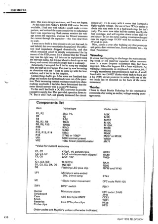
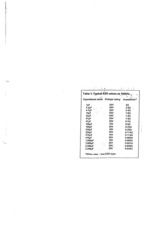
providesa longer battery-life,'iiedugintgh e livel it Table l, from whicht Dubilier,p rwides he bulb ceasest9 a functiona usefulg uide, l.1 in qery[tor. tests ignalc anh oweverb e so low at highEsR values Stre addition,i r ytu ar" unsurew hat readingto expecitt ,s "ury "nougtiio thata *ut"'u ccuracsyu "o-f*iro" ffersI.practicea *iiri",i-iili;; n no scillatoro utputo about5 V peak-to-peaisk -
f rr9- yoor?"il-stockedl uy-J"r""t oiyti"r. a goodc om-promise.
The-meterh as good rf an oscilloscopies protectiona gainstp not availablet,lacingt he h e followings im- probe, u"ros ple u .f,.g"d methodc .upu"it-, anb eu But sed.this C onnect shouldo a 1o f resistorb eiw""n "ourr" u" uuoia"a.thet r fr" estI onryi eadsa eui ndt Juut" urn thes for ^uie",concernis jiiig;:
et-zeroco ntrolV R2 (shown . the. 'mains mootfrinbgl ock,,i .". u *an,
incorrectlya s a preseti ri ric, .s*f as1-,g -.tql wise.A dvancbth es cttingo f wil slowly. [ti"r*t: "i;t il*]l'ii-""paciior. we att tnow tr,atn is capacitor. half wayp ointt heo scillatorw ill start Iust:aftetrh e. can abtlnb;" .rrif1f pun.l *n"o " piLr-suppty has,: up andt he meter's faibd l; siilt up. If you are-oft he typew ith a tendency pointerw ill deflect.c 1rry oq.yntil th-e-buzzeior unds ro sucha cciJent,i iwour,l ue steadilyA. r thisp oint the oscillator'so utputs hould fruiiiito wke a couple: be E F"fy ;F;; 6ack-to-babakc rossth e merer,sin pur.,, cloqet o 5v.peak+o-peakN. ote that with eacha dj.ust- rrris stiouta mentt he pointerw ill twitch briefly liotect the meter,b ut it won,t help your as the bulb se[des, heart- ot yo'otp robes- in the evento f sucha misfor- givingt hei mpressiotnh att hep otentiometeisr no5r, tune.rt's gLoJpracticet" al*rr*ga irtit capacitor with
Table 1: Typical ESR values at 100kH2...
I
Capacitance value Voltage rating lmpedance*
ltrF
2.21tF
4.7pF
10pF
221tF
471tF
471tF
100pF
100pF
2201tF
2201tF
4701tY
4701tF
1,000pF
1,000pF
2,2001tF
2,2001tF
63V
50v
2 5 V '
50v
16V
35V
16V
35V
16V
35V
16V
25V
25V,
35V
4Q
2.8A
2.4A
1.9c)
1.3c)
1.3cr
o.7a
0.scr
0.2scr
0.25fi
0.1 14Q
0.114c)
0.065fi
0.0650
0.041c)
0.036ct
0.034f)
50v
50v
50v
*When new - low-ESR type.
a mains-type bulb - it is always reassurine to have a
visual indication that little charge remains. See warning
note later.
Inductonce
As the meter operatesa t l00kHz, any inductancein the
circuit under test becomes significani. The loudspeaker
that reads.8C)o n your coqventionalo hmmetera pp"*s
to be nearly open-circuit wittr ttre ESR meter.
This propert_yc an be quite useful. When testinga line
oxtput stage for example you might find that there,s a
short-circuit across the hansistor. In this event there are
in general three possibilities, (a) the transistor is short-circuit,
(b) the line output transformer has a primary-to-secondary
short, or (c) the HT line has a short-circuit
across it. If the short-circuit is still present when the
ESR meter is used, the transistor is almost certainly the
culprit: in the other two cases the ESR meter will give
an open-circuitr eadingb ecauseo f the inductanceo f the
transformer's primaly winding.
. Video headt esterso perateb y measuring,in effect, the
inductanceo f the head.I ts impedancef alls as the gap
deteriorates with wear. Althou;h this meter operates at
a frequency that's inappropriate for a video heid, it can
436
April 1999 TELEVTSTON](https://image.slidesharecdn.com/esr-capacitor-meter-project-141209080954-conversion-gate02/85/Esr-capacitor-meter-project-9-320.jpg)


The document discusses the design of a practical ESR meter circuit that measures the equivalent series resistance of electrolytic capacitors. It begins by providing background on ESR and its importance in determining capacitor quality. The circuit uses an operational amplifier configured as an oscillator, amplifier, and comparator to measure capacitor ESR. The document provides details on the op-amp design and precision inverting amplifier circuit to explain how the ESR meter works and measures capacitor ESR without regard for other circuit components.