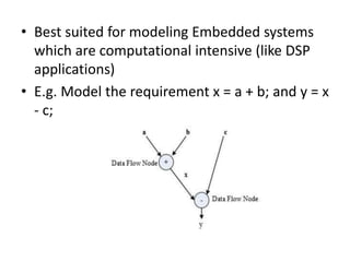
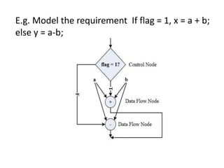
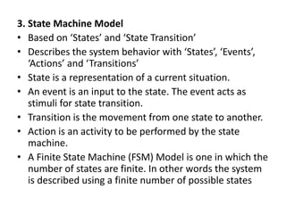
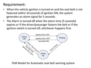
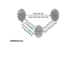
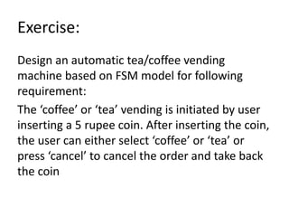
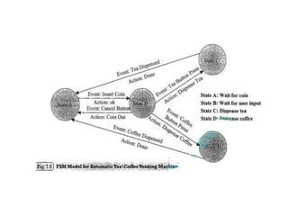
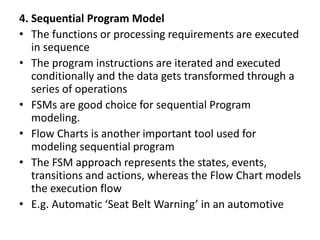
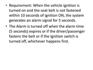
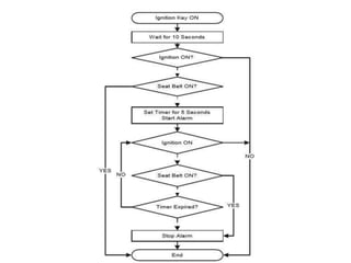
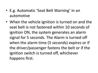
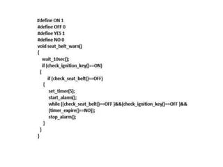
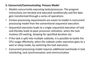
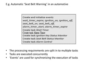
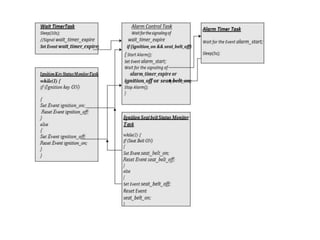
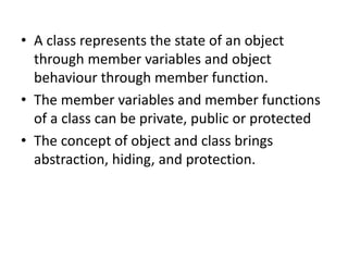
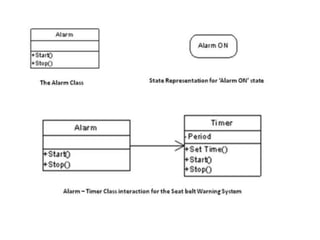
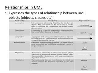
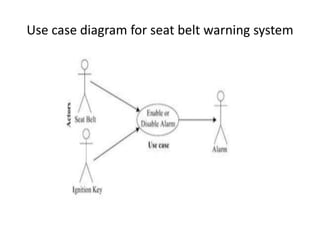
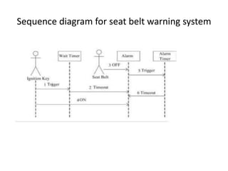
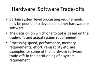
ES Module 2
Hardware Software Co-Design and
Program Modelling
Traditional Embedded System
Development Approach
• The hardware software partitioning is done at an
early stage
• Engineers from the software group take care of
the software architecture development and
implementation, and engineers from the
hardware group are responsible for building the
hardware required for the product
• There is less interaction between the two teams
and the development happens either serially or
in parallel and once the hardware and software
are ready, the integration is performed
Fundamental issues in H/w S/w Co-
design
1. Model Selection
• A Model captures and describes the system
characteristics
• A model is a formal system consisting of objects and
composition rules
• It is hard to make a decision on which model should be
followed in a particular system design.
• Most often designers switch between a variety of
models from the requirements specification to the
implementation aspect of the system design
• The objectives vary with each phase
2. Architecture Selection
• A model only captures the system characteristics and
does not provide information on ‘how the system can
be manufactured?’
• The architecture specifies how a system is going to
implement in terms of the number and types of
different components and the interconnection among
them
• Controller architecture, Datapath Architecture,
Complex Instruction Set Computing (CISC), Reduced
Instruction Set Computing (RISC), Very long Instruction
Word Computing (VLIW), Single Instruction Multiple
Data (SIMD), Multiple Instruction Multiple Data
(MIMD) etc are the commonly used architectures in
system design
3. Language Selection
• A programming Language captures a ‘Computational
Model’ and maps it into architecture
• A model can be captured using multiple programming
languages like C, C++, C#, Java etc for software
implementations and languages like VHDL, System C,
Verilog etc for hardware implementations
• Certain languages are good in capturing certain
computational model. For example, C++ is a good
candidate for capturing an object oriented model.
• The only pre-requisite in selecting a programming
language for capturing a model is that the language
should capture the model easily
4. Partitioning of System Requirements into H/w
and S/w
• Implementation aspect of a System level
Requirement
• It may be possible to implement the system
requirements in either hardware or software
(firmware)
• Various hardware software trade-offs like
performance, re-usability, effort etc are used
for making a decision on the hardware-
software partitioning
Computational Models in Embedded
Design
1. Data Flow Graph/Diagram (DFG) Model
• Translates the data processing requirements into a data
flow graph
• A data driven model in which the program execution is
determined by data.
• Emphasizes on the data and operations on the data which
transforms the input data to output data.
• A visual model in which the operation on the data (process)
is represented using a block (circle) and data flow is
represented using arrows. An inward arrow to the process
(circle) represents input data and an outward arrow from
the process (circle) represents output data in DFG notation
• Best suited for modeling Embedded systems
which are computational intensive (like DSP
applications)
• E.g. Model the requirement x = a + b; and y = x
- c;
• Data path: The data flow path from input to
output
• A DFG model is said to be acyclic DFG (ADFG)
if it doesn’t contain multiple values for the
input variable and multiple output values for a
given set of input(s). Feedback inputs (Output
is feed back to Input), events etc are examples
for non-acyclic inputs. A DFG model translates
the program as a single sequential process
execution.
2. Control Data Flow Graph/Diagram (CDFG) Model
• Translates the data processing requirements into a data flow
graph
• Model applications involving conditional program execution
• Contains both data operations and control operations
• Uses Data Flow Graph (DFG) as element and conditional
(constructs) as decision makers.
• contains both data flow nodes and decision nodes, whereas
DFG contains only data flow nodes
• A visual model in which the operation on the data (process) is
represented using a block (circle) and data flow is represented
using arrows. An inward arrow to the process (circle)
represents input data and an outward arrow from the process
(circle) represents output data in DFG notation.
• The control node is represented by a
‘Diamond’ block which is the decision making
element in a normal flow chart based design
• Translates the requirement, which is modeled
to a concurrent process model
• The decision on which process is to be
executed is determined by the control node
• Capturing of image and storing it in the format
selected (bmp, jpg, tiff, etc.) in a digital
camera is a typical example of an application
that can be modeled with CDFG
E.g. Model the requirement If flag = 1, x = a + b;
else y = a-b;
3. State Machine Model
• Based on ‘States’ and ‘State Transition’
• Describes the system behavior with ‘States’, ‘Events’,
‘Actions’ and ‘Transitions’
• State is a representation of a current situation.
• An event is an input to the state. The event acts as
stimuli for state transition.
• Transition is the movement from one state to another.
• Action is an activity to be performed by the state
machine.
• A Finite State Machine (FSM) Model is one in which the
number of states are finite. In other words the system
is described using a finite number of possible states
• Most of the time State Machine model translates the
requirements into sequence driven program
• The Hierarchical/Concurrent Finite State Machine Model
(HCFSM) is an extension of the FSM for supporting
concurrency and hierarchy
• HCFSM extends the conventional state diagrams by the
AND, OR decomposition of States together with inter
level transitions and a broadcast mechanism for
communicating between concurrent processes
• HCFSM uses statecharts for capturing the states,
transitions, events and actions. The Harel Statechart,
UML State diagram etc are examples for popular
statecharts used for the HCFSM modeling of embedded
systems
• E.g. Automatic ‘Seat Belt Warning’ in an automotive
Requirement:
• When the vehicle ignition is turned on and the seat belt is not
fastened within 10 seconds of ignition ON, the system
generates an alarm signal for 5 seconds.
• The Alarm is turned off when the alarm time (5 seconds)
expires or if the driver/passenger fastens the belt or if the
ignition switch is turned off, whichever happens first.
FSM Model for Automatic seat belt warning system
Exercise:
Design an automatic tea/coffee vending
machine based on FSM model for following
requirement:
The ‘coffee’ or ‘tea’ vending is initiated by user
inserting a 5 rupee coin. After inserting the coin,
the user can either select ‘coffee’ or ‘tea’ or
press ‘cancel’ to cancel the order and take back
the coin
4. Sequential Program Model
• The functions or processing requirements are executed
in sequence
• The program instructions are iterated and executed
conditionally and the data gets transformed through a
series of operations
• FSMs are good choice for sequential Program
modeling.
• Flow Charts is another important tool used for
modeling sequential program
• The FSM approach represents the states, events,
transitions and actions, whereas the Flow Chart models
the execution flow
• E.g. Automatic ‘Seat Belt Warning’ in an automotive
• Requirement: When the vehicle ignition is
turned on and the seat belt is not fastened
within 10 seconds of ignition ON, the system
generates an alarm signal for 5 seconds.
• The Alarm is turned off when the alarm time
(5 seconds) expires or if the driver/passenger
fastens the belt or if the ignition switch is
turned off, whichever happens first.
• E.g. Automatic ‘Seat Belt Warning’ in an
automotive
• When the vehicle ignition is turned on and the
seat belt is not fastened within 10 seconds of
ignition ON, the system generates an alarm
signal for 5 seconds. The Alarm is turned off
when the alarm time (5 seconds) expires or if
the driver/passenger fastens the belt or if the
ignition switch is turned off, whichever
happens first.
5. Concurrent/Communicating Process Model
• Models concurrently executing tasks/processes. The program
instructions are iterated and executed conditionally and the data
gets transformed through a series of operations
• Certain processing requirements are easier to model in concurrent
processing model than the conventional sequential execution.
• Sequential execution leads to a single sequential execution of task
and thereby leads to poor processor utilization, when the task
involves I/O waiting, sleeping for specified duration etc.
• If the task is split into multiple subtasks, it is possible to tackle the
CPU usage effectively, when the subtask under execution goes to a
wait or sleep mode, by switching the task execution.
• Concurrent processing model requires additional overheads in task
scheduling, task synchronization and communication
E.g. Automatic ‘Seat Belt Warning’ in an automotive
• The processing requirements are split in to multiple tasks
• Tasks are executed concurrently
• ‘Events’ are used for synchronizing the execution of tasks
6. Object-Oriented Model
• The Object-Oriented Model is an object based
model for modelling system requirement.
• Object-Oriented Model brings re-usability,
maintainability and productivity in system design.
• In Object-Oriented Modelling, object is an entity
used for representing or modelling a particular
piece of the system.
• Each object is characterised by a set of unique
behaviour and state.
• A class is an abstract description of a set of
objects and it can be considered as a ‘blueprint’
of an object.
• A class represents the state of an object
through member variables and object
behaviour through member function.
• The member variables and member functions
of a class can be private, public or protected
• The concept of object and class brings
abstraction, hiding, and protection.
Introduction to Unified Modeling
Language (UML)
• Unified Modeling Language (UML) is a visual
modeling language for Object Oriented Design
(OOD).
• UML helps in all phases of system design
through a set of unique diagrams for
requirements capturing, designing and
deployment.
UML Building Blocks:
Things -An abstraction of the UML Model
Relationships -An entity which express the
type of relationship between UML elements
(objects, classes etc)
Diagrams -UML Diagrams give a pictorial
representation of the static aspects,
behavioral aspects and organization and
management of different modules (classes,
packages etc) of the system
Things
• Structural things: Represents mostly the static parts of
a UML model. They are also known as ‘classifiers’.
Class, interface, use case, use case realization
(collaboration), active class, component and node are
the structural things in UML.
• Behavioral things: Represents mostly the dynamic parts
of a UML model. Interaction, state machine and
activity are the behavioral things in UML.
• Grouping things: Are the organizational parts of a UML
model. Package and subsystem are the grouping things
in UML.
• Annotational things: Are the explanatory parts of a
UML model. Note is the Annotational thing in UML.
Relationships in UML
• Expresses the types of relationship between UML
objects (objects, classes etc)
UML diagrams
• UML diagrams give pictorial representation of static
aspects, behavioural aspects and organization and
management of different modules(into classes,
packages) of the systems
1. Static Diagrams: Diagram representing the static
(structural) aspects of the system. Class Diagram,
Object Diagram, Component Diagram, Package
Diagram, Composite Structure Diagram and
Deployment Diagram falls under this category
Class diagram of Order System of an application
Component diagram of Online Shopping
Package diagram
Deployment Diagram for Lucidchart
2.Behavioural Diagram
• It represents the dynamic(behavioural)
aspects of the system. Use case diagram,
sequence diagram, state diagram,
communication diagram, activity diagram,
timing diagram and interaction diagram are
diagrams in UML
Use case diagram for seat belt warning system
Exercise:
Draw use case diagram of an automated teller
machine (ATM) or the automatic banking
machine (ABM) provides to the bank customers.
Sequence diagram for seat belt warning system
Exercise:
Draw Sequence diagram of an automated teller
machine (ATM) or the automatic banking
machine (ABM) provides to the bank customers.
Collaboration (communication) diagram for
telephone system
Exercise:
Draw collaboration diagram of an automated
teller machine (ATM) System
State Chart Diagram
Notations
Example:
The system contain three states
-Diagnosis mode
-Operational mode
-Fault mode
State Chart Diagram
Exercise:
Draw state chart diagram of an automated teller
machine (ATM) System
Activity Diagram
Notations:
Activity diagram for online shopping system
Exercise:
Draw activity diagram of an automated teller
machine (ATM) System
Hardware Software Trade-offs
• Certain system level processing requirements
may be possible to develop in either hardware or
software
• The decision on which one to opt is based on the
trade-offs and actual system requirement
• Processing speed, performance, memory
requirements, effort, re-usability etc. are
examples for some of the hardware software
trade-offs in the partitioning of a system
requirement

Es_module2ppt.pptx

  • 1.
    ES Module 2 HardwareSoftware Co-Design and Program Modelling
  • 2.
    Traditional Embedded System DevelopmentApproach • The hardware software partitioning is done at an early stage • Engineers from the software group take care of the software architecture development and implementation, and engineers from the hardware group are responsible for building the hardware required for the product • There is less interaction between the two teams and the development happens either serially or in parallel and once the hardware and software are ready, the integration is performed
  • 3.
    Fundamental issues inH/w S/w Co- design 1. Model Selection • A Model captures and describes the system characteristics • A model is a formal system consisting of objects and composition rules • It is hard to make a decision on which model should be followed in a particular system design. • Most often designers switch between a variety of models from the requirements specification to the implementation aspect of the system design • The objectives vary with each phase
  • 4.
    2. Architecture Selection •A model only captures the system characteristics and does not provide information on ‘how the system can be manufactured?’ • The architecture specifies how a system is going to implement in terms of the number and types of different components and the interconnection among them • Controller architecture, Datapath Architecture, Complex Instruction Set Computing (CISC), Reduced Instruction Set Computing (RISC), Very long Instruction Word Computing (VLIW), Single Instruction Multiple Data (SIMD), Multiple Instruction Multiple Data (MIMD) etc are the commonly used architectures in system design
  • 5.
    3. Language Selection •A programming Language captures a ‘Computational Model’ and maps it into architecture • A model can be captured using multiple programming languages like C, C++, C#, Java etc for software implementations and languages like VHDL, System C, Verilog etc for hardware implementations • Certain languages are good in capturing certain computational model. For example, C++ is a good candidate for capturing an object oriented model. • The only pre-requisite in selecting a programming language for capturing a model is that the language should capture the model easily
  • 6.
    4. Partitioning ofSystem Requirements into H/w and S/w • Implementation aspect of a System level Requirement • It may be possible to implement the system requirements in either hardware or software (firmware) • Various hardware software trade-offs like performance, re-usability, effort etc are used for making a decision on the hardware- software partitioning
  • 7.
    Computational Models inEmbedded Design 1. Data Flow Graph/Diagram (DFG) Model • Translates the data processing requirements into a data flow graph • A data driven model in which the program execution is determined by data. • Emphasizes on the data and operations on the data which transforms the input data to output data. • A visual model in which the operation on the data (process) is represented using a block (circle) and data flow is represented using arrows. An inward arrow to the process (circle) represents input data and an outward arrow from the process (circle) represents output data in DFG notation
  • 8.
    • Best suitedfor modeling Embedded systems which are computational intensive (like DSP applications) • E.g. Model the requirement x = a + b; and y = x - c;
  • 9.
    • Data path:The data flow path from input to output • A DFG model is said to be acyclic DFG (ADFG) if it doesn’t contain multiple values for the input variable and multiple output values for a given set of input(s). Feedback inputs (Output is feed back to Input), events etc are examples for non-acyclic inputs. A DFG model translates the program as a single sequential process execution.
  • 10.
    2. Control DataFlow Graph/Diagram (CDFG) Model • Translates the data processing requirements into a data flow graph • Model applications involving conditional program execution • Contains both data operations and control operations • Uses Data Flow Graph (DFG) as element and conditional (constructs) as decision makers. • contains both data flow nodes and decision nodes, whereas DFG contains only data flow nodes • A visual model in which the operation on the data (process) is represented using a block (circle) and data flow is represented using arrows. An inward arrow to the process (circle) represents input data and an outward arrow from the process (circle) represents output data in DFG notation.
  • 11.
    • The controlnode is represented by a ‘Diamond’ block which is the decision making element in a normal flow chart based design • Translates the requirement, which is modeled to a concurrent process model • The decision on which process is to be executed is determined by the control node • Capturing of image and storing it in the format selected (bmp, jpg, tiff, etc.) in a digital camera is a typical example of an application that can be modeled with CDFG
  • 12.
    E.g. Model therequirement If flag = 1, x = a + b; else y = a-b;
  • 13.
    3. State MachineModel • Based on ‘States’ and ‘State Transition’ • Describes the system behavior with ‘States’, ‘Events’, ‘Actions’ and ‘Transitions’ • State is a representation of a current situation. • An event is an input to the state. The event acts as stimuli for state transition. • Transition is the movement from one state to another. • Action is an activity to be performed by the state machine. • A Finite State Machine (FSM) Model is one in which the number of states are finite. In other words the system is described using a finite number of possible states
  • 14.
    • Most ofthe time State Machine model translates the requirements into sequence driven program • The Hierarchical/Concurrent Finite State Machine Model (HCFSM) is an extension of the FSM for supporting concurrency and hierarchy • HCFSM extends the conventional state diagrams by the AND, OR decomposition of States together with inter level transitions and a broadcast mechanism for communicating between concurrent processes • HCFSM uses statecharts for capturing the states, transitions, events and actions. The Harel Statechart, UML State diagram etc are examples for popular statecharts used for the HCFSM modeling of embedded systems • E.g. Automatic ‘Seat Belt Warning’ in an automotive
  • 15.
    Requirement: • When thevehicle ignition is turned on and the seat belt is not fastened within 10 seconds of ignition ON, the system generates an alarm signal for 5 seconds. • The Alarm is turned off when the alarm time (5 seconds) expires or if the driver/passenger fastens the belt or if the ignition switch is turned off, whichever happens first. FSM Model for Automatic seat belt warning system
  • 17.
    Exercise: Design an automatictea/coffee vending machine based on FSM model for following requirement: The ‘coffee’ or ‘tea’ vending is initiated by user inserting a 5 rupee coin. After inserting the coin, the user can either select ‘coffee’ or ‘tea’ or press ‘cancel’ to cancel the order and take back the coin
  • 19.
    4. Sequential ProgramModel • The functions or processing requirements are executed in sequence • The program instructions are iterated and executed conditionally and the data gets transformed through a series of operations • FSMs are good choice for sequential Program modeling. • Flow Charts is another important tool used for modeling sequential program • The FSM approach represents the states, events, transitions and actions, whereas the Flow Chart models the execution flow • E.g. Automatic ‘Seat Belt Warning’ in an automotive
  • 20.
    • Requirement: Whenthe vehicle ignition is turned on and the seat belt is not fastened within 10 seconds of ignition ON, the system generates an alarm signal for 5 seconds. • The Alarm is turned off when the alarm time (5 seconds) expires or if the driver/passenger fastens the belt or if the ignition switch is turned off, whichever happens first.
  • 22.
    • E.g. Automatic‘Seat Belt Warning’ in an automotive • When the vehicle ignition is turned on and the seat belt is not fastened within 10 seconds of ignition ON, the system generates an alarm signal for 5 seconds. The Alarm is turned off when the alarm time (5 seconds) expires or if the driver/passenger fastens the belt or if the ignition switch is turned off, whichever happens first.
  • 24.
    5. Concurrent/Communicating ProcessModel • Models concurrently executing tasks/processes. The program instructions are iterated and executed conditionally and the data gets transformed through a series of operations • Certain processing requirements are easier to model in concurrent processing model than the conventional sequential execution. • Sequential execution leads to a single sequential execution of task and thereby leads to poor processor utilization, when the task involves I/O waiting, sleeping for specified duration etc. • If the task is split into multiple subtasks, it is possible to tackle the CPU usage effectively, when the subtask under execution goes to a wait or sleep mode, by switching the task execution. • Concurrent processing model requires additional overheads in task scheduling, task synchronization and communication
  • 25.
    E.g. Automatic ‘SeatBelt Warning’ in an automotive • The processing requirements are split in to multiple tasks • Tasks are executed concurrently • ‘Events’ are used for synchronizing the execution of tasks
  • 27.
    6. Object-Oriented Model •The Object-Oriented Model is an object based model for modelling system requirement. • Object-Oriented Model brings re-usability, maintainability and productivity in system design. • In Object-Oriented Modelling, object is an entity used for representing or modelling a particular piece of the system. • Each object is characterised by a set of unique behaviour and state. • A class is an abstract description of a set of objects and it can be considered as a ‘blueprint’ of an object.
  • 28.
    • A classrepresents the state of an object through member variables and object behaviour through member function. • The member variables and member functions of a class can be private, public or protected • The concept of object and class brings abstraction, hiding, and protection.
  • 29.
    Introduction to UnifiedModeling Language (UML) • Unified Modeling Language (UML) is a visual modeling language for Object Oriented Design (OOD). • UML helps in all phases of system design through a set of unique diagrams for requirements capturing, designing and deployment.
  • 30.
    UML Building Blocks: Things-An abstraction of the UML Model Relationships -An entity which express the type of relationship between UML elements (objects, classes etc) Diagrams -UML Diagrams give a pictorial representation of the static aspects, behavioral aspects and organization and management of different modules (classes, packages etc) of the system
  • 31.
    Things • Structural things:Represents mostly the static parts of a UML model. They are also known as ‘classifiers’. Class, interface, use case, use case realization (collaboration), active class, component and node are the structural things in UML. • Behavioral things: Represents mostly the dynamic parts of a UML model. Interaction, state machine and activity are the behavioral things in UML. • Grouping things: Are the organizational parts of a UML model. Package and subsystem are the grouping things in UML. • Annotational things: Are the explanatory parts of a UML model. Note is the Annotational thing in UML.
  • 36.
    Relationships in UML •Expresses the types of relationship between UML objects (objects, classes etc)
  • 38.
    UML diagrams • UMLdiagrams give pictorial representation of static aspects, behavioural aspects and organization and management of different modules(into classes, packages) of the systems 1. Static Diagrams: Diagram representing the static (structural) aspects of the system. Class Diagram, Object Diagram, Component Diagram, Package Diagram, Composite Structure Diagram and Deployment Diagram falls under this category
  • 41.
    Class diagram ofOrder System of an application
  • 42.
    Component diagram ofOnline Shopping
  • 43.
  • 44.
  • 45.
    2.Behavioural Diagram • Itrepresents the dynamic(behavioural) aspects of the system. Use case diagram, sequence diagram, state diagram, communication diagram, activity diagram, timing diagram and interaction diagram are diagrams in UML
  • 47.
    Use case diagramfor seat belt warning system
  • 48.
    Exercise: Draw use casediagram of an automated teller machine (ATM) or the automatic banking machine (ABM) provides to the bank customers.
  • 50.
    Sequence diagram forseat belt warning system
  • 51.
    Exercise: Draw Sequence diagramof an automated teller machine (ATM) or the automatic banking machine (ABM) provides to the bank customers.
  • 53.
  • 54.
    Exercise: Draw collaboration diagramof an automated teller machine (ATM) System
  • 56.
  • 57.
    Example: The system containthree states -Diagnosis mode -Operational mode -Fault mode
  • 58.
  • 59.
    Exercise: Draw state chartdiagram of an automated teller machine (ATM) System
  • 61.
  • 62.
    Activity diagram foronline shopping system
  • 63.
    Exercise: Draw activity diagramof an automated teller machine (ATM) System
  • 65.
    Hardware Software Trade-offs •Certain system level processing requirements may be possible to develop in either hardware or software • The decision on which one to opt is based on the trade-offs and actual system requirement • Processing speed, performance, memory requirements, effort, re-usability etc. are examples for some of the hardware software trade-offs in the partitioning of a system requirement