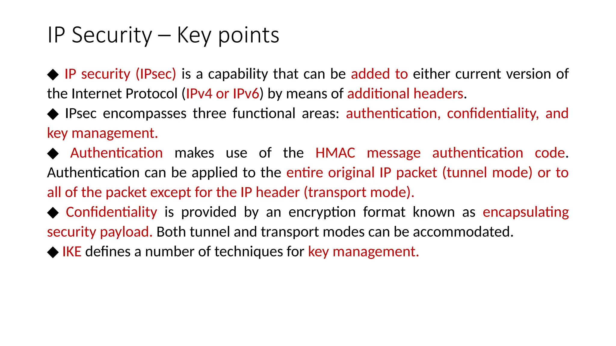
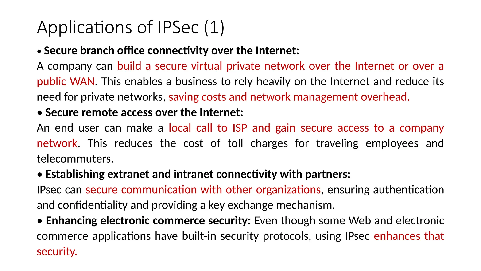
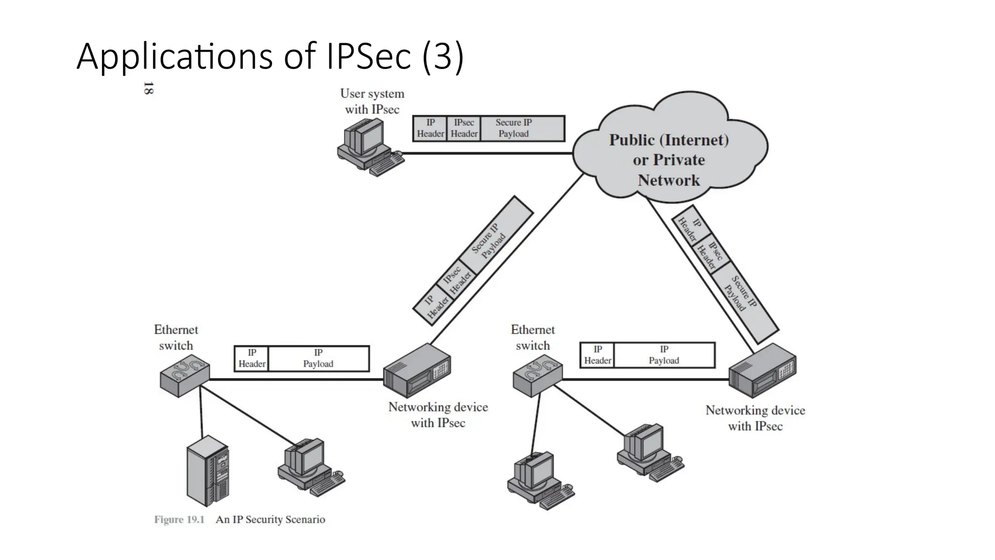
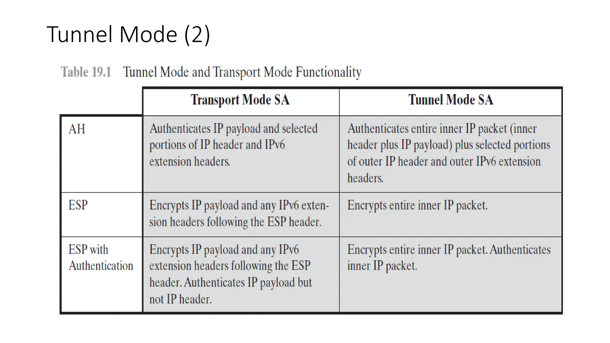
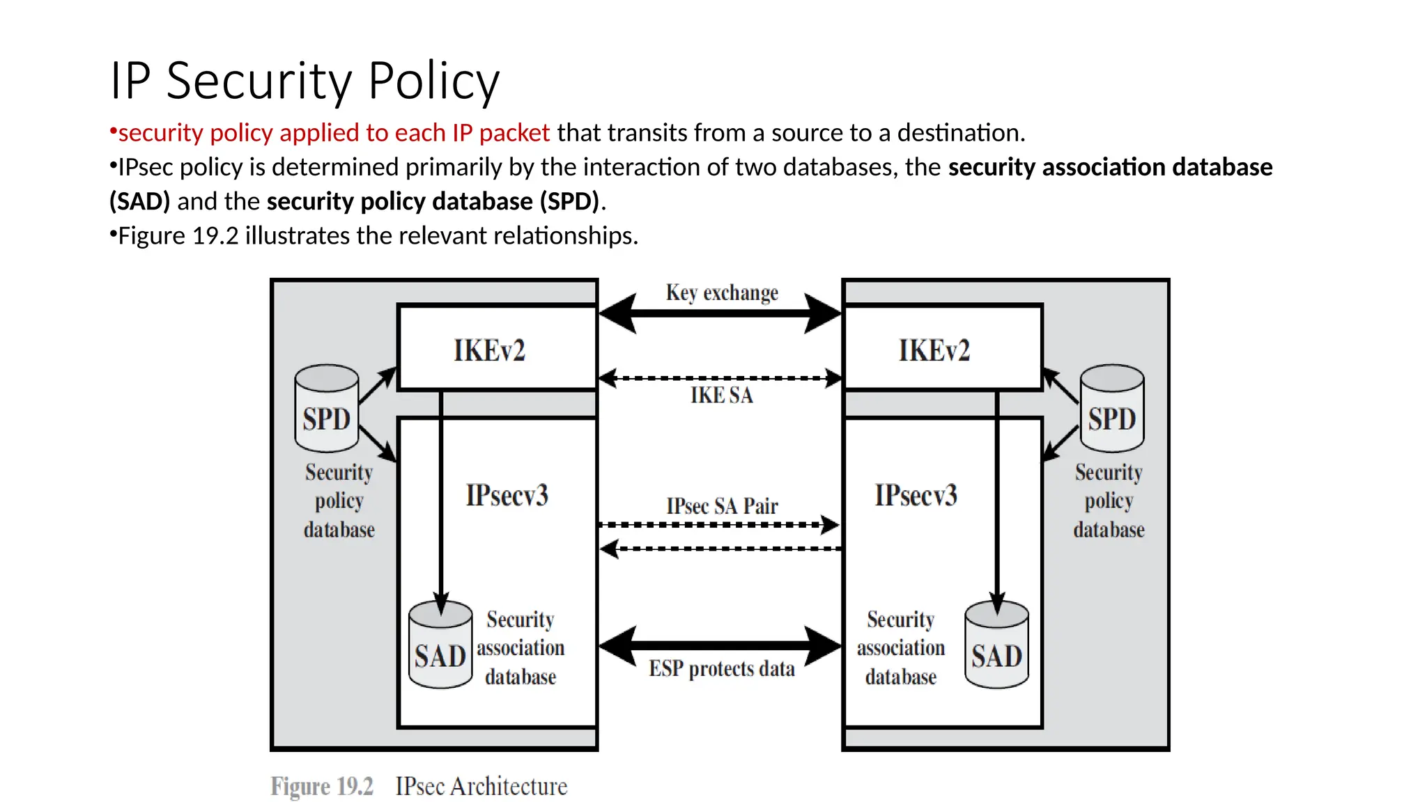
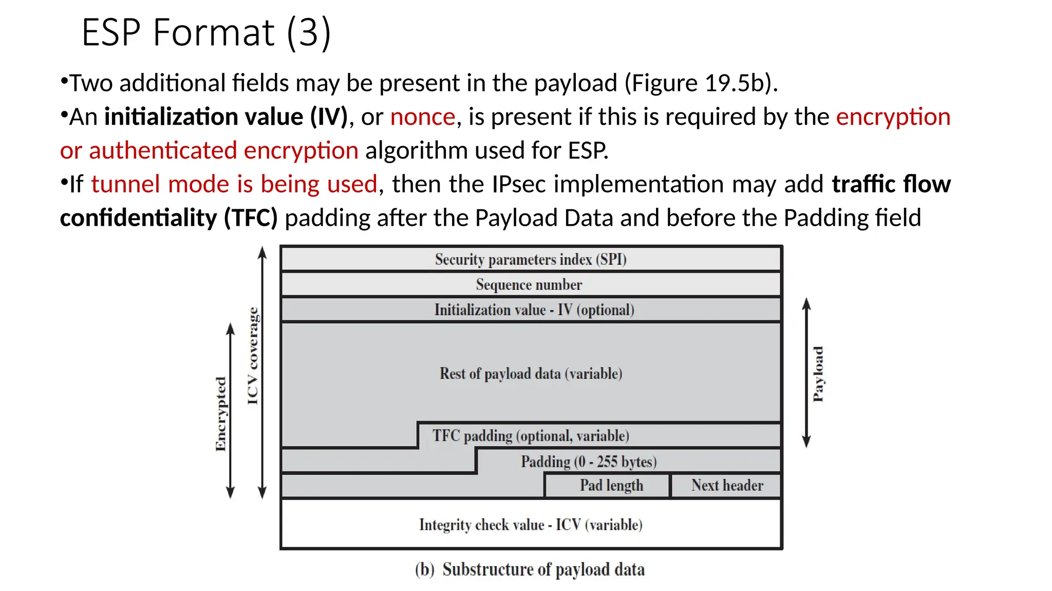
Module 3
IP Security Overview
IP Security Topics
• IP Security Overview
• IP Security Architecture
• Authentication Header
• Encapsulating security payload
• Combining security associations
• Internet Key Exchange.
IP Security – Key points
◆ IP security (IPsec) is a capability that can be added to either current version of
the Internet Protocol (IPv4 or IPv6) by means of additional headers.
◆ IPsec encompasses three functional areas: authentication, confidentiality, and
key management.
◆ Authentication makes use of the HMAC message authentication code.
Authentication can be applied to the entire original IP packet (tunnel mode) or to
all of the packet except for the IP header (transport mode).
◆ Confidentiality is provided by an encryption format known as encapsulating
security payload. Both tunnel and transport modes can be accommodated.
◆ IKE defines a number of techniques for key management.
Applications of IPSec (1)
• Secure branch office connectivity over the Internet:
A company can build a secure virtual private network over the Internet or over a
public WAN. This enables a business to rely heavily on the Internet and reduce its
need for private networks, saving costs and network management overhead.
• Secure remote access over the Internet:
An end user can make a local call to ISP and gain secure access to a company
network. This reduces the cost of toll charges for traveling employees and
telecommuters.
• Establishing extranet and intranet connectivity with partners:
IPsec can secure communication with other organizations, ensuring authentication
and confidentiality and providing a key exchange mechanism.
• Enhancing electronic commerce security: Even though some Web and electronic
commerce applications have built-in security protocols, using IPsec enhances that
security.
Applications of IPSec (2)
•IPsec guarantees that all traffic at IP level is both encrypted and authenticated
•Thus, all distributed applications (including remote login, client/server, e-mail, file
transfer,Web access, and so on) can be secured.
•Figure 19.1 is a typical scenario of IPsec usage.
•An organization maintains LANs at dispersed locations.
•Nonsecure IP traffic is conducted on each LAN.
•For traffic offsite, through some sort of private or public WAN, IPsec protocols are
used.
•These protocols operate in networking devices, such as a router or firewall, that
connect each LAN to the outside world.
•The IPsec networking device will typically encrypt and compress all traffic going
into the WAN and decrypt and decompress traffic coming from the WAN; these
operations are transparent to workstations and servers on the LAN.
Applications of IPSec (3)
Benefits of IPSec
• When IPsec is implemented in a firewall or router, provides strong security to all
traffic crossing the perimeter.
• IPsec in a firewall is resistant to bypass if all traffic from the outside must use IP
and the firewall is the only means of entrance from the Internet into the
organization.
• IPsec is below the transport layer (TCP, UDP) and so is transparent to applications.
There is no need to change software on a user or server system when IPsec is
implemented in the firewall or router. Even if IPsec is implemented in end systems,
upper-layer software, including applications, is not affected.
• IPsec can be transparent to end users. There is no need to train users on security
mechanisms, issue keying material on a per-user basis, or revoke keying material
when users leave the organization.
• IPsec can provide security for individual users if needed. This is useful for offsite
workers and for setting up a secure virtual subnetwork within an organization for
sensitive applications.
Routing Applications
•IPsec can assure that
• A router advertisement (a new router advertises its presence) comes from
an authorized router.
• A neighbor advertisement (a router seeks to establish or maintain a
neighbor relationship with a router in another routing domain) comes from
an authorized router.
• A redirect message comes from the router to which the initial IP packet
was sent.
• A routing update is not forged.
• Without such security measures, an opponent can disrupt
communications or divert some traffic.
• Open Shortest Path First (OSPF) should be run on top IPsec.
IPSec Documents
• Architecture: Covers the general concepts, security requirements, definitions, and
mechanisms defining IPsec technology. The current specification is RFC 4301, Security
Architecture for the Internet Protocol.
• Authentication Header (AH): AH is an extension header to provide message
authentication. The current specification is RFC 4302, IP Authentication Header.
• Encapsulating Security Payload (ESP): ESP consists of an encapsulating header and trailer
used to provide encryption or combined encryption/authentication.
• Internet Key Exchange (IKE): This is a collection of documents describing the key
management schemes for use with IPsec. The main specification is RFC 4306, Internet Key
Exchange (IKEv2) Protocol.
• Cryptographic algorithms: This category encompasses a large set of documents that
define and describe cryptographic algorithms for encryption, message authentication,
pseudorandom functions (PRFs), and cryptographic key exchange.
• Other: There are a variety of other IPsec-related RFCs, including those dealing with
security policy and management information base (MIB) content.
IPSec Services
•Two protocols are used to provide security: an authentication protocol designated
by the header of the protocol, Authentication Header (AH); and a combined
encryption/authentication protocol designated by the format of the packet for that
protocol, Encapsulating Security Payload (ESP).
RFC 4301 lists the following services:
• Access control
• Connectionless integrity
• Data origin authentication
• Rejection of replayed packets (a form of partial sequence integrity)
• Confidentiality (encryption)
• Limited traffic flow confidentiality
Transport Mode
•Transport mode provides protection primarily for upper-layer
protocols.
•That is, transport mode protection extends to the payload of an IP
packet.
•Examples include a TCP or UDP segment or an ICMP packet, all of
which operate directly above IP in a host protocol stack.
•Typically, transport mode is used for end-to-end communication
between two hosts
•ESP in transport mode encrypts and optionally authenticates the IP
payload but not the IP header.
•AH in transport mode authenticates the IP payload and selected
portions of the IP header.
Tunnel Mode (1)
•Tunnel mode protects the entire IP packet.
•To achieve this, after the AH or ESP fields are added to the IP packet, the entire
packet plus security fields is treated as the payload of new outer IP packet with a
new outer IP header.
•The entire original, inner, packet travels through a tunnel from one point of an IP
network to another; no routers along the way are able to examine the inner IP
header.
•Because the original packet is encapsulated, the new, larger packet may have
totally different source and destination addresses, adding to the security.
•Tunnel mode is used when one or both ends of a security association (SA) are a
security gateway, such as a firewall or router that implements IPsec.
Tunnel Mode (2)
IP Security Policy
•security policy applied to each IP packet that transits from a source to a destination.
•IPsec policy is determined primarily by the interaction of two databases, the security association database
(SAD) and the security policy database (SPD).
•Figure 19.2 illustrates the relevant relationships.
Security Associations
•An association is a one-way logical connection between a sender and a receiver that affords
security services to the traffic carried on it.
•If a peer relationship is needed for two-way secure exchange, then two security associations are
required. Security services are afforded to an SA for the use of AH or ESP, but not both.
•A security association is uniquely identified by three parameters.
• Security Parameters Index (SPI): A bit string assigned to this SA and having local significance only.
The SPI is carried in AH and ESP headers to enable the receiving system to select the SA under
which a received packet will be processed.
• IP Destination Address: This is the address of the destination endpoint of the SA, which may be
an end-user system or a network system such as a firewall or router.
• Security Protocol Identifier: This field from the outer IP header indicates whether the association
is an AH or ESP security association.
•Hence, in any IP packet, the security association is uniquely identified by the Destination Address in
the IPv4 or IPv6 header and the SPI in the enclosed extension header (AH or ESP).
Security Association Database (1)
•In each IPsec implementation, there is a nominal Security Association Database
that defines the parameters associated with each SA.
•A security association is normally defined by the following parameters in an SAD
entry.
• Security Parameter Index: A 32-bit value selected by the receiving end of an SA
to uniquely identify the SA. In an SAD entry for an outbound SA, the SPI is used to
construct the packet’s AH or ESP header. In an SAD entry for an inbound SA, the SPI
is used to map traffic to the appropriate SA.
• Sequence Number Counter: A 32-bit value used to generate the Sequence
Number field in AH or ESP headers.
• Sequence Counter Overflow: A flag indicating whether overflow of the Sequence
Number Counter should generate an auditable event and prevent further
transmission of packets on this SA (required for all implementations).
Security Association Database (2)
• Anti-Replay Window: Used to determine whether an inbound AH or ESP packet is
a replay.
• AH Information: Authentication algorithm, keys, key lifetimes, and related
parameters being used with AH
• ESP Information: Encryption and authentication algorithm, keys, initialization
values, key lifetimes, and related parameters being used with ESP
• Lifetime of this Security Association: A time interval or byte count after which an
SA must be replaced with a new SA (and new SPI) or terminated, plus an indication
of which of these actions should occur
• IPsec Protocol Mode: Tunnel, transport, or wildcard.
• Path MTU: Any observed path maximum transmission unit (maximum size of a
packet that can be transmitted without fragmentation) and aging variables.
Security Policy Database (1)
•An SPD contains entries, each of which defines a subset of IP traffic and points to
an SA for that traffic.
•Each SPD entry is defined by a set of IP and upper-layer protocol field values,
called selectors.
•In effect, these selectors are used to filter outgoing traffic to map it into a
particular SA.
•Outbound processing obeys the following general sequence for each IP packet.
1. Compare the values of the appropriate fields in the packet (the selector fields)
against the SPD to find a matching SPD entry, which will point to zero or more SAs.
2. Determine the SA if any for this packet and its associated SPI.
3. Do the required IPsec processing (i.e., AH or ESP processing).
Security Policy Database (2)
•The following selectors determine an SPD entry:
• Remote IP Address: This may be a single IP address, an enumerated list or range of addresses, or
a wildcard (mask) address. The latter two are required to support more than one destination system
sharing the same SA (e.g., behind a firewall).
• Local IP Address: This may be a single IP address, an enumerated list or range of addresses, or a
wildcard (mask) address. The latter two are required to support more than one source system
sharing the same SA (e.g., behind a firewall).
• Next Layer Protocol: The IP protocol header includes a field that designates the protocol
operating over IP. If AH or ESP is used, then this IP protocol header immediately precedes the AH or
ESP header in the packet.
•Name: A user identifier from the operating system. This is not a field in the IP or upper-layer
headers but is available if IPsec is running on the same operating system as the user.
• Local and Remote Ports: These may be individual TCP or UDP port values, an enumerated list of
ports, or a wildcard port.
•Table 19.2 provides an example of an SPD on a host system (as opposed to a network system such
as a firewall or router).
Security Policy Database (3)
Security Policy Database (4)
This table reflects the following configuration:
•A local network configuration consists of two networks.
•The basic corporate network configuration has the IP network number 1.2.3.0/24.
•The local configuration also includes a secure LAN, often known as a DMZ, that is
identified as 1.2.4.0/24. The DMZ is protected from both the outside world and the
rest of the corporate LAN by firewalls.
•The host in this example has the IP address 1.2.3.10, and it is authorized to
connect to the server 1.2.4.10 in the DMZ.
•For example, UDP port 500 is the designated port for IKE.
•Any traffic from the local host to a remote host for purposes of an IKE exchange
bypasses the IPsec processing.
IP Traffic Processing
•IPsec is executed on a packet-by-packet basis.
•When IPsec is implemented, each outbound IP packet is
processed by the IPsec logic before transmission, and each
inbound packet is processed by the IPsec logic after reception
and before passing the packet contents on to the next higher
layer (e.g., TCP or UDP).
IP Traffic Processing – Outbound Packets
•Figure 19.3 highlights the main elements of IPsec processing for outbound traffic.
•A block of data from a higher layer, such as TCP, is passed down to the IP layer and an IP packet is
formed, consisting of an IP header and an IP body.
1. IPsec searches the SPD for a match to this packet.
2. If no match is found, then the packet is discarded and an error message is generated.
3. If a match is found, further processing is determined by the first matching entry in the SPD. If the
policy for this packet is DISCARD, then the packet is discarded. If the policy is BYPASS, then there is
no further IPsec processing; the packet is forwarded to the network for transmission.
4. If the policy is PROTECT, then a search is made of the SAD for a matching entry. If no entry is
found, then IKE is invoked to create an SA with the appropriate keys, and an entry is made in the SA.
5. The matching entry in the SAD determines the processing for this packet. Either encryption,
authentication, or both can be performed, and either transport or tunnel mode can be used. The
packet is then forwarded to the network for transmission.
IP Traffic Processing – Outbound Packets
IP Traffic Processing – Inbound Packets
•Figure 19.4 highlights the main elements of IPsec processing for inbound traffic. An
incoming IP packet triggers the IPsec processing.
1. IPsec determines whether this is an unsecured IP packet or one that has ESP or
AH headers/trailers, by examining the IP Protocol field (IPv4) or Next Header field
(IPv6).
2. If the packet is unsecured, IPsec searches the SPD for a match to this packet. If
the first matching entry has a policy of BYPASS, the IP header is processed and
stripped off and the packet body is delivered to the next higher layer, such as TCP. If
the first matching entry has a policy of PROTECT or DISCARD, or if there is no
matching entry, the packet is discarded.
•3. For a secured packet, IPsec searches the SAD. If no match is found, the packet is
discarded. Otherwise, IPsec applies the appropriate ESP or AH processing. Then,
the IP header is processed and stripped off and the packet body is delivered to the
next higher layer, such as TCP.
IP Traffic Processing – Inbound Packets
Encapsulating Security Payload
•ESP can be used to provide confidentiality, data origin authentication,
connectionless integrity, an anti-replay service , and traffic flow
confidentiality.
•The set of services provided depends on options selected at the time
of Security Association (SA) establishment and on the location of the
implementation in a network topology.
•ESP can work with a variety of encryption and authentication
algorithms, including authenticated encryption algorithms such as GCM
(Galois/Counter Mode)
ESP Format (1)
•Figure 19.5a shows the top-level format of an ESP packet. It contains the following fields.
• Security Parameters Index (32 bits): Identifies a security association.
• Sequence Number (32 bits): A monotonically increasing counter value; this provides an
anti-replay function
• Payload Data (variable): This is a transport-level segment (transport mode) or IP packet
(tunnel mode) that is protected by encryption.
• Padding (0 – 255 bytes): The purpose of this field is to pad the data bits to desired size.
• Pad Length (8 bits): Indicates the number of pad bytes immediately preceding this field.
• Next Header (8 bits): Identifies the type of data contained in the payload data field by
identifying the first header in that payload.
• Integrity Check Value (variable): A variable-length field (must be an integral number of
32-bit words) that contains the Integrity Check Value computed over the ESP packet minus
the Authentication Data field.
ESP Format (2)
ESP Format (3)
•Two additional fields may be present in the payload (Figure 19.5b).
•An initialization value (IV), or nonce, is present if this is required by the encryption
or authenticated encryption algorithm used for ESP.
•If tunnel mode is being used, then the IPsec implementation may add traffic flow
confidentiality (TFC) padding after the Payload Data and before the Padding field
Encryption and Authentication Algorithms
•The Payload Data, Padding, Pad Length, and Next Header fields are encrypted by
the ESP service.
•The ICV field is optional. It is present only if the integrity service is selected and is
provided by either a separate integrity algorithm or a combined mode algorithm
that uses an ICV.
•The ICV is computed after the encryption is performed.
•This order of processing facilitates rapid detection and rejection of replayed or
bogus packets by the receiver prior to decrypting the packet, hence potentially
reducing the impact of denial of service (DoS) attacks.
•It also allows for the possibility of parallel processing of packets at the receiver,
i.e., decryption can take place in parallel with integrity checking.
Padding
•The Padding field serves several purposes:
• If an encryption algorithm requires the plaintext to be a multiple of
some number of bytes, the Padding field is used to expand the plaintext
to the required length.
• The ESP format requires that the Pad Length and Next Header fields
be right aligned within a 32-bit word. Equivalently, the ciphertext must
be an integer multiple of 32 bits.
• Additional padding may be added to provide partial traffic-flow
confidentiality by concealing the actual length of the payload.
Anti replay Service (1)
•A replay attack is one in which an attacker obtains a copy of an
authenticated packet and later transmits it to the intended destination.
•The Sequence Number field is designed to thwart such attacks.
•When a new SA is established, the sender initializes a sequence
number counter to 0.
•Each time that a packet is sent on this SA, the sender increments the
counter and places the value in the Sequence Number field.
•Thus, the first value to be used is 1.
•If anti-replay is enabled, the sender must not allow the sequence
number to cycle past 2^32 – 1 back to zero.
Anti replay Service (2)
•Otherwise, there would be multiple valid packets with the same sequence
number.
•If the limit of 2^32 – 1 is reached, the sender should terminate this SA and
negotiate a new SA with a new key.
•Because IP is a connectionless, unreliable service, the protocol does not guarantee
that packets will be delivered in order and does not guarantee that all packets will
be delivered.
•Therefore, the IPsec authentication document dictates that the receiver should
implement a window of size W , with a default of W=64.
•The right edge of the window represents the highest sequence number, N, so far
received for a valid packet.
•For any packet with a sequence number in the range from N-W+1 to N that has
been correctly received, the corresponding slot in the window is marked (Figure
19.6).
Anti replay Service (3)
Anti replay Service (4)
• Inbound processing proceeds as follows when a packet is received:
1. If the received packet falls within the window and is new, the MAC is
checked. If the packet is authenticated, the corresponding slot in the
window is marked.
2. If the received packet is to the right of the window and is new, the
MAC is checked. If the packet is authenticated, the window is advanced
so that this sequence number is the right edge of the window, and the
corresponding slot in the window is marked.
3. If the received packet is to the left of the window or if authentication
fails, the packet is discarded; this is an auditable event.
Transport and Tunnel Modes (1)
•Figure 19.7 shows two ways in which the IPsec ESP
service can be used.
•In the upper part of the figure, encryption (and
optionally authentication) is provided directly between
two hosts.
•Figure 19.7b shows how tunnel mode operation can
be used to set up a virtual private network.
Transport and Tunnel Modes (2)
Transport and Tunnel Modes (3)
Transport Mode ESP (1)
• Transport mode ESP is used to encrypt and optionally authenticate
the data carried by IP (e.g., a TCP segment), as shown in Figure 19.8b.
•For this mode using IPv4, the ESP header is inserted into the IP packet
immediately before the transport-layer header (e.g., TCP, UDP, ICMP),
and an ESP trailer (Padding, Pad Length, and Next Header fields) is
placed after the IP packet.
•If authentication is selected, the ESP Authentication Data field is added
after the ESP trailer.
•The entire transport-level segment plus the ESP trailer are encrypted.
•Authentication covers all of the ciphertext plus the ESP header.
Transport Mode ESP (2)
•In the context of IPv6, ESP is viewed as an end-to-end payload; that is,
it is not examined or processed by intermediate routers.
•Therefore, the ESP header appears after the IPv6 base header and the
hop-by-hop, routing, and fragment extension headers.
•The destination options extension header could appear before or after
the ESP header, depending on the semantics desired.
•For IPv6, encryption covers the entire transport-level segment plus the
ESP trailer plus the destination options extension header if it occurs
after the ESP header.
•Again, authentication covers the ciphertext plus the ESP header.
Transport Mode ESP (3)
•Transport mode operation may be summarized as follows.
1. At the source, the block of data consisting of the ESP trailer plus the entire
transport-layer segment is encrypted and the plaintext of this block is replaced with
its ciphertext to form the IP packet for transmission. Authentication is added if this
option is selected.
2. The packet is then routed to the destination. Each intermediate router needs to
examine and process the IP header plus any plaintext IP extension headers but
does not need to examine the ciphertext.
3. The destination node examines and processes the IP header plus any plaintext IP
extension headers. Then, based on the SPI in the ESP header, the destination node
decrypts the remainder of the packet to recover the plaintext transport-layer
segment.
•One drawback to this mode is that it is possible to do traffic analysis on the
transmitted packets.
Tunnel Mode ESP (1)
•Tunnel mode ESP encrypts an entire IP packet (Figure 19.8c).
•For this mode, the ESP header is prefixed to the packet, and the packet plus the
ESP trailer is encrypted.
•This method can be used to counter traffic analysis.
•Therefore, it is necessary to encapsulate the entire block with a new IP header
that will contain sufficient information for routing but not for traffic analysis.
•The tunnel mode is useful in a configuration that includes a firewall or security
gateway that protects a trusted network from external networks.
•In this latter case, encryption occurs only between an external host and the
security gateway or between two security gateways.
•This relieves hosts on the internal network of the processing burden of encryption
and simplifies the key distribution task by reducing the number of needed keys.
Tunnel Mode ESP (2)
•Consider a case in which an external host wishes to communicate with a host on an internal
network protected by a firewall, and in which ESP is implemented in the external host and the
firewalls.
•The following steps occur for transfer of a transport- layer segment from the external host to the
internal host.
1. The source prepares an inner IP packet with a destination address of the target internal host. This
packet is prefixed by an ESP header; then the packet and ESP trailer are encrypted and
Authentication Data may
be added. The resulting block is encapsulated with a new IP header whose destination address is
the firewall; this forms the outer IP packet.
2. The outer packet is routed to the destination firewall. Each intermediate router needs to examine
and process the outer IP header plus any outer IP extension headers but does not need to examine
the ciphertext.
3. The destination firewall examines and processes the outer IP header plus any outer IP extension
headers. Then, based on the SPI in the ESP header, the destination node decrypts the remainder of
the packet to
recover the plaintext inner IP packet. This packet is then transmitted to the internal network.
4. The inner packet is routed through zero or more routers in the internal network to the
Tunnel Mode ESP (3)
Combining Security Associations (1)
•An individual SA can implement either the AH or ESP protocol but not both.
•Sometimes a particular traffic flow will call for the services provided by both AH
and ESP.
•Further, a particular traffic flow may require IPsec services between hosts and, for
that same flow, separate services between security gateways, such as firewalls.
•In all of these cases, multiple SAs must be employed for the same traffic flow to
achieve the desired IPsec services.
•The term security association bundle refers to a sequence of SAs through which
traffic must be processed to provide a desired set of IPsec services.
•The SAs in a bundle may terminate at different endpoints or the same endpoints.
Combining Security Associations (2)
•Security associations may be combined into bundles in two ways:
• Transport adjacency: Refers to applying more than one security protocol to the
same IP packet without invoking tunneling.
This approach to combining AH and ESP allows for only one level of combination
• Iterated tunneling: Refers to the application of multiple layers of security
protocols effected through IP tunneling.
This approach allows for multiple levels of nesting, since each tunnel can originate
or terminate at a different IPsec site along the path.
•The two approaches can be combined, for example, by having a transport SA
between hosts travel part of the way through a tunnel SA between security
gateways.
Authentication plus Confidentiality
• Encryption and authentication can be combined to transmit
an IP packet that has both confidentiality and authentication
between hosts.
• We look at several approaches.
• ESP WITH AUTHENTICATION OPTION
• TRANSPORT ADJACENCY
• TRANSPORT-TUNNEL BUNDLE
ESP with Authentication Option
•This approach is illustrated in Figure 19.8.
•In this approach, the user first applies ESP to the data to be protected and then
appends the authentication data field. There are two subcases:
• Transport mode ESP: Authentication and encryption apply to the IP payload
delivered to the host, but the IP header is not protected.
• Tunnel mode ESP: Authentication applies to the entire IP packet delivered to the
outer IP destination address (e.g., a firewall), and authentication is performed at
that destination.
•The entire inner IP packet is protected by the privacy mechanism for delivery to
the inner IP destination.
•For both cases, authentication applies to the ciphertext rather than the plaintext.
Transport Adjacency
•Another way to apply authentication after encryption is to use two bundled
transport SAs, with the inner being an ESP SA and the outer being an AH SA.
•In this case, ESP is used without its authentication option.
•Because the inner SA is a transport SA, encryption is applied to the IP payload.
•The resulting packet consists of an IP header followed by an ESP.
•AH is then applied in transport mode, so that authentication covers the ESP plus
the original IP header (and extensions) except for mutable fields.
•The advantage of this approach is that the authentication covers more fields,
including the source and destination IP addresses.
•The disadvantage is the overhead of two SAs versus one SA.
Transport Tunnel Bundle
•The use of authentication before encryption might be preferable for several reasons.
•First, because the authentication data are protected by encryption, it is impossible for anyone to
intercept the message and alter the authentication data without detection.
•Second, it may be desirable to store the authentication information with the message at the
destination for later reference.
•It is more convenient to do this if the authentication information applies to the unencrypted
message; otherwise the message would have to be re-encrypted to verify the authentication
information.
•One approach to applying authentication before encryption between two hosts is to use a bundle
consisting of an inner AH transport SA and an outer ESP tunnel SA.
•In this case, authentication is applied to the IP payload plus the IP header (and extensions) except
for mutable fields.
•The resulting IP packet is then processed in tunnel mode by ESP; the result is that the entire,
authenticated inner packet is encrypted and a new outer IP header (and extensions) is added.
Basic Combinations of Security Associations (1)
•The IPsec Architecture document lists four examples of combinations
of SAs that must be supported by compliant IPsec hosts (e.g.,
workstation, server) or security gateways (e.g. firewall, router).
• These are illustrated in Figure 19.10.
•The lower part of each case in the figure represents the physical
connectivity of the elements; the upper part represents logical
connectivity via one or more nested SAs.
•Each SA can be either AH or ESP. For host-to-host SAs, the mode may
be either transport or tunnel; otherwise it must be tunnel mode.
Basic Combinations of Security Associations (2)
Basic Combinations of Security Associations (3)
Case 1. All security is provided between end systems that
implement IPsec.
For any two end systems to communicate via an SA, they must
share the appropriate secret keys. Among the possible
combinations are
a. AH in transport mode
b. ESP in transport mode
c. ESP followed by AH in transport mode (an ESP SA inside an
AH SA)
d. Any one of a, b, or c inside an AH or ESP in tunnel mode
Basic Combinations of Security Associations (4)
• Case 2. Security is provided only between gateways (routers,
firewalls, etc.) and no hosts implement IPsec.
• This case illustrates simple virtual private network support.
• The security architecture document specifies that only a
single tunnel SA is needed for this case.
• The tunnel could support AH, ESP, or ESP with the
authentication option.
• Nested tunnels are not required, because the IPsec services
apply to the entire inner packet.
Basic Combinations of Security Associations (5)
•Case 3. This builds on case 2 by adding end-to-end security.
•The same combinations discussed for cases 1 and 2 are allowed
here.
•The gateway-to-gateway tunnel provides either authentication,
confidentiality, or both for all traffic between end systems.
•When the gateway-to-gateway tunnel is ESP, it also provides a
limited form of traffic confidentiality.
•Individual hosts can implement any additional IPsec services
required for given applications or given users by means of end-to-
end SAs.
Basic Combinations of Security Associations (6)
•Case 4. This provides support for a remote host that
uses the Internet to reach an organization’s firewall
and then to gain access to some server or workstation
behind the firewall.
•Only tunnel mode is required between the remote
host and the firewall.
•As in case 1, one or two SAs may be used between the
remote host and the local host.
Internet Key Exchange (1)
•The key management portion of IPsec involves the determination and distribution
of secret keys.
•A typical requirement is four keys for communication between two applications:
transmit and receive pairs for both integrity and confidentiality.
•The IPsec Architecture document mandates support for two types of key
management:
• Manual: A system administrator manually configures each system with its own
keys and with the keys of other communicating systems. This is practical for small,
relatively static environments.
• Automated: An automated system enables the on-demand creation of keys for
SAs and facilitates the use of keys in a large distributed system with an evolving
configuration.
Internet Key Exchange (2)
The default automated key management protocol for IPsec is referred to as
ISAKMP/Oakley and consists of the following elements:
• Oakley Key Determination Protocol: Oakley is a key exchange protocol based on
the Diffie-Hellman algorithm but provides added security. Oakley is generic in that
it does not dictate specific formats.
• Internet Security Association and Key Management Protocol (ISAKMP):
ISAKMP provides a framework for Internet key management and provides specific
protocol support, including formats, for the negotiation of security attributes.
ISAKMP consists of a set of message types that enable the use of a variety of key
exchange algorithms.
Key Determination Protocol (1)
•IKE key determination is a refinement of the Diffie-Hellman key exchange
algorithm.
•Recall that Diffie-Hellman involves the following interaction between users A and
B.
•There is prior agreement on two global parameters: q, a large prime number; and
α a primitive root of q.
•A selects a random integer as its private key and transmits to B its public key .
•Similarly, B selects a random integer as its private key and transmits to A its public
key .
•Each side can now compute the secret session key:
Key Determination Protocol (2)
•The Diffie-Hellman algorithm has two attractive features:
• Secret keys are created only when needed. There is no need to store secret keys
for a long period of time, exposing them to increased vulnerability.
• The exchange requires no pre-existing infrastructure other than an agreement on
the global parameters.
However, there are several weaknesses to Diffie-Hellman, as pointed out in
• It does not provide any information about the identities of the parties.
• It is subject to a man-in-the-middle attack, in which a third party C impersonates B while
communicating with A and impersonates A while communicating with B. Both A and B end up
negotiating a key with C, which can then listen to and pass on traffic.
Key Determination Protocol (3)
•The man-in-the-middle attack proceeds as
Key Determination Protocol (4)
• It is computationally intensive. As a result, it is vulnerable to
a clogging attack, in which an opponent requests a high
number of keys.
• The victim spends considerable computing resources doing
useless modular exponentiation rather than real work.
• IKE key determination is designed to retain the advantages of
Diffie-Hellman, while countering its weaknesses.
Features of IKE Key Determination (1)
•The IKE key determination algorithm is characterized by five important
features:
1. It employs a mechanism known as cookies to thwart clogging attacks.
2. It enables the two parties to negotiate a group; this, in essence,
specifies the global parameters of the Diffie-Hellman key exchange.
3. It uses nonces to ensure against replay attacks.
4. It enables the exchange of Diffie-Hellman public key values.
5. It authenticates the Diffie-Hellman exchange to thwart man-in-the-
middle attacks.
Features of IKE Key Determination (2)
•In a clogging attack, an opponent forges the source address of a legitimate user
and sends a public Diffie- Hellman key to the victim.
•The victim then performs a modular exponentiation to compute the secret key.
•Repeated messages of this type can clog the victim’s system with useless work.
•The cookie exchange requires that each side send a pseudorandom number, the
cookie, in the initial message, which the other side acknowledges.
•This acknowledgment must be repeated in the first message of the Diffie-Hellman
key exchange.
•If the source address was forged, the opponent gets no answer.
•Thus, an opponent can only force a user to generate acknowledgments and not to
perform the Diffie-Hellman calculation.
Features of IKE Key Determination (3)
•IKE mandates that cookie generation satisfy three basic requirements:
1. The cookie must depend on the specific parties. This prevents an attacker from obtaining a cookie
using a real IP address and UDP port and then using it to swamp the victim with requests from
randomly chosen IP addresses or ports.
2. It must not be possible for anyone other than the issuing entity to generate cookies that will be
accepted by that entity. This implies that the issuing entity will use local secret information in the
generation and subsequent verification of a cookie. It must not be possible to deduce this secret
information from any particular cookie. The point of this requirement is that the issuing entity need
not save copies of its cookies, which are then more vulnerable to discovery, but can verify an
incoming cookie acknowledgment when it needs to.
3. The cookie generation and verification methods must be fast to thwart attacks intended to
sabotage processor resources.
The recommended method for creating the cookie is to perform a fast hash (e.g., MD5) over the IP
Source and Destination addresses, the UDP Source and Destination ports, and a locally generated
secret value.
Features of IKE Key Determination (4)
•IKE key determination supports the use of different groups for the Diffie-Hellman key exchange. Each group
includes the definition of the two global parameters and the identity of the algorithm. The current specification
includes the following groups.
Features of IKE Key Determination (5)
•IKE key determination employs nonces to ensure against replay attacks. Each
nonce is a locally generated pseudorandom number.
•Nonces appear in responses and are encrypted during certain portions of the
exchange to secure their use.
•Three different authentication methods can be used with IKE key determination:
• Digital signatures: The exchange is authenticated by signing a mutually
obtainable hash; each party encrypts the hash with its private key. The hash is
generated over important parameters, such as user IDs and nonces.
• Public-key encryption: The exchange is authenticated by encrypting parameters
such as IDs and nonces with the sender’s private key.
• Symmetric-key encryption: A key derived by some out-of-band mechanism can
be used to authenticate the exchange by symmetric encryption of exchange
parameters.
IKE V2 Exchanges (1)
•The IKEv2 protocol involves the exchange of messages in pairs.
•The first two pairs of exchanges are referred to as the initial exchanges (Figure
19.11a).
•In the first exchange, the two peers exchange information concerning
cryptographic algorithms and other security parameters they are willing to use
along with nonces and Diffie-Hellman (DH) values.
•The result of this exchange is to set up a special SA called the IKE SA
•This SA defines parameters for a secure channel between the peers over which
subsequent message exchanges occur.
•Thus, all subsequent IKE message exchanges are protected by encryption and
message authentication.
IKE V2 Exchanges (2)
•In the second exchange, the two parties authenticate one another and set up a
first IPsec SA to be placed in the SADB and used for protecting ordinary
communications between the peers.
•Thus, four messages are needed to establish the first SA for general use.
•The CREATE_CHILD_SA exchange can be used to establish further SAs for
protecting traffic.
•The informational exchange is used to exchange management information, IKEv2
error messages, and other notifications.
Header and Payload Formats (1)
•IKE defines procedures and packet formats to establish, negotiate, modify, and
delete security associations.
•As part of SA establishment, IKE defines payloads for exchanging key generation
and authentication data.
•These payload formats provide a consistent framework independent of the
specific key exchange protocol, encryption algorithm, and authentication
mechanism.
•IKE HEADER FORMAT An IKE message consists of an IKE header followed by one or
more payloads.
•All of this is carried in a transport protocol.
•The specification dictates that implementations must support the use of UDP for
the transport protocol.
•Figure 19.12a shows the header format for an IKE message.
Header and Payload Formats (2)
•It consists of the following fields.
• Initiator SPI (64 bits): A value chosen by the initiator to identify a
unique IKE security association (SA).
• Responder SPI (64 bits): A value chosen by the responder to identify
a unique IKE SA.
• Next Payload (8 bits): Indicates the type of the first payload in the
message;
• Major Version (4 bits): Indicates major version of IKE in use.
• Minor Version (4 bits): Indicates minor version in use.
Header and Payload Formats (3)
• Exchange Type (8 bits): Indicates the type of exchange
• Flags (8 bits): Indicates specific options set for this IKE exchange. Three bits are
defined so far. The initiator bit indicates whether this packet is sent by the SA
initiator.
• The version bit indicates whether the transmitter is capable of using a
higher major version number than the one currently indicated.
• The response bit indicates whether this is a response to a message containing the
same message ID.
• Message ID (32 bits): Used to control retransmission of lost packets and
matching of requests and responses.
• Length (32 bits): Length of total message (header plus all payloads) in octets.
IKE Payload Types (1)
•All IKE payloads begin with the same generic payload header shown in Figure
19.12b.
•The Next Payload field has a value of 0 if this is the last payload in the message;
otherwise its value is the type of the next payload.
•The Payload Length field indicates the length in octets of this payload, including
the generic payload header.
•The critical bit is 0 if the sender wants the recipient to skip this payload if it does
not understand the payload type code in the Next Payload field of the previous
payload.
•It is set to 1 if the sender wants the recipient to reject this entire message if it does
not understand the payload type.
IKE Payload Types (2)
•Table 19.3 summarizes the payload types defined for IKE and
lists the fields, or parameters, that are part of each payload.
•The SA payload is used to begin the establishment of an SA.
•The payload has a complex, hierarchical structure.
•The payload may contain multiple proposals.
•Each proposal may contain multiple protocols.
•Each protocol may contain multiple transforms.
•And each transform may contain multiple attributes
IKE Payload Types (3)
•These elements are formatted as substructures within the payload as follows.
• Proposal: This substructure includes a proposal number, a protocol ID (AH, ESP, or
IKE), an indicator of the number of transforms, and then a transform substructure.
If more than one protocol is to be included in a
proposal, then there is a subsequent proposal substructure with the same proposal
number.
• Transform: Different protocols support different transform types. The transforms
are used primarily to define cryptographic algorithms to be used with a particular
protocol.
• Attribute: Each transform may include attributes that modify or complete the
specification of the transform. An example is key length.
IKE Payload Types (4)
•The Key Exchange payload can be used for a variety of key exchange techniques, including Oakley, Diffie-
Hellman, and the RSA-based key exchange used by PGP.
•The Key Exchange data field contains the data required to generate a session key and is dependent on the key
exchange algorithm used.
•The Identification payload is used to determine the identity of communicating peers and may be used for
determining authenticity of information. Typically the ID Data field will contain an IPv4 or IPv6 address.
•The Certificate payload transfers a public-key certificate. The Certificate Encoding field indicates the type of
certificate or certificate-related information, which may include the following:
• PKCS #7 wrapped X.509 certificate
• PGP certificate
• DNS signed key
• X.509 certificate—signature
• X.509 certificate—key exchange
• Kerberos tokens
• Certificate Revocation List (CRL)
• Authority Revocation List (ARL)
• SPKI certificate
IKE Payload Types (5)
•At any point in an IKE exchange, the sender may include a Certificate Request
payload to request the certificate of the other communicating entity.
•The payload may list more than one certificate type that is acceptable and more
than one certificate authority that is acceptable.
•The Authentication payload contains data used for message authentication
purposes.
•The authentication method types so far defined are RSA digital signature, shared-
key message integrity code, and DSS digital signature.
•The Nonce payload contains random data used to guarantee liveness during an
exchange and to protect against replay attacks.
•The Notify payload contains either error or status information associated with this
SA or this SA negotiation.
IKE Payload Types (6)
•The following table lists the IKE notify messages.
•The Delete payload indicates one or more SAs that the sender has
deleted from its database and that therefore are no longer valid.
•The Vendor ID payload contains a vendor-defined constant.
•The constant is used by vendors to identify and recognize remote
instances of their implementations.
•This mechanism allows a vendor to experiment with new features
while maintaining backward compatibility.
•The Traffic Selector payload allows peers to identify packet flows for
processing by IPsec services.
IKE Payload Types (7)
•The Encrypted payload contains other payloads in encrypted
form.
•The encrypted payload format is similar to that of ESP.
•It may include an IV if the encryption algorithm requires it
and an ICV if authentication is selected.
•The Configuration payload is used to exchange configuration
information between IKE peers.
•The Extensible Authentication Protocol (EAP) payload allows
IKE SAs to be authenticated using EAP.
End of Module 3

EOC MODULE 3 IP security - SR.pptx engineering college

  • 1.
  • 2.
    IP Security Topics •IP Security Overview • IP Security Architecture • Authentication Header • Encapsulating security payload • Combining security associations • Internet Key Exchange.
  • 3.
    IP Security –Key points ◆ IP security (IPsec) is a capability that can be added to either current version of the Internet Protocol (IPv4 or IPv6) by means of additional headers. ◆ IPsec encompasses three functional areas: authentication, confidentiality, and key management. ◆ Authentication makes use of the HMAC message authentication code. Authentication can be applied to the entire original IP packet (tunnel mode) or to all of the packet except for the IP header (transport mode). ◆ Confidentiality is provided by an encryption format known as encapsulating security payload. Both tunnel and transport modes can be accommodated. ◆ IKE defines a number of techniques for key management.
  • 4.
    Applications of IPSec(1) • Secure branch office connectivity over the Internet: A company can build a secure virtual private network over the Internet or over a public WAN. This enables a business to rely heavily on the Internet and reduce its need for private networks, saving costs and network management overhead. • Secure remote access over the Internet: An end user can make a local call to ISP and gain secure access to a company network. This reduces the cost of toll charges for traveling employees and telecommuters. • Establishing extranet and intranet connectivity with partners: IPsec can secure communication with other organizations, ensuring authentication and confidentiality and providing a key exchange mechanism. • Enhancing electronic commerce security: Even though some Web and electronic commerce applications have built-in security protocols, using IPsec enhances that security.
  • 5.
    Applications of IPSec(2) •IPsec guarantees that all traffic at IP level is both encrypted and authenticated •Thus, all distributed applications (including remote login, client/server, e-mail, file transfer,Web access, and so on) can be secured. •Figure 19.1 is a typical scenario of IPsec usage. •An organization maintains LANs at dispersed locations. •Nonsecure IP traffic is conducted on each LAN. •For traffic offsite, through some sort of private or public WAN, IPsec protocols are used. •These protocols operate in networking devices, such as a router or firewall, that connect each LAN to the outside world. •The IPsec networking device will typically encrypt and compress all traffic going into the WAN and decrypt and decompress traffic coming from the WAN; these operations are transparent to workstations and servers on the LAN.
  • 6.
  • 7.
    Benefits of IPSec •When IPsec is implemented in a firewall or router, provides strong security to all traffic crossing the perimeter. • IPsec in a firewall is resistant to bypass if all traffic from the outside must use IP and the firewall is the only means of entrance from the Internet into the organization. • IPsec is below the transport layer (TCP, UDP) and so is transparent to applications. There is no need to change software on a user or server system when IPsec is implemented in the firewall or router. Even if IPsec is implemented in end systems, upper-layer software, including applications, is not affected. • IPsec can be transparent to end users. There is no need to train users on security mechanisms, issue keying material on a per-user basis, or revoke keying material when users leave the organization. • IPsec can provide security for individual users if needed. This is useful for offsite workers and for setting up a secure virtual subnetwork within an organization for sensitive applications.
  • 8.
    Routing Applications •IPsec canassure that • A router advertisement (a new router advertises its presence) comes from an authorized router. • A neighbor advertisement (a router seeks to establish or maintain a neighbor relationship with a router in another routing domain) comes from an authorized router. • A redirect message comes from the router to which the initial IP packet was sent. • A routing update is not forged. • Without such security measures, an opponent can disrupt communications or divert some traffic. • Open Shortest Path First (OSPF) should be run on top IPsec.
  • 9.
    IPSec Documents • Architecture:Covers the general concepts, security requirements, definitions, and mechanisms defining IPsec technology. The current specification is RFC 4301, Security Architecture for the Internet Protocol. • Authentication Header (AH): AH is an extension header to provide message authentication. The current specification is RFC 4302, IP Authentication Header. • Encapsulating Security Payload (ESP): ESP consists of an encapsulating header and trailer used to provide encryption or combined encryption/authentication. • Internet Key Exchange (IKE): This is a collection of documents describing the key management schemes for use with IPsec. The main specification is RFC 4306, Internet Key Exchange (IKEv2) Protocol. • Cryptographic algorithms: This category encompasses a large set of documents that define and describe cryptographic algorithms for encryption, message authentication, pseudorandom functions (PRFs), and cryptographic key exchange. • Other: There are a variety of other IPsec-related RFCs, including those dealing with security policy and management information base (MIB) content.
  • 10.
    IPSec Services •Two protocolsare used to provide security: an authentication protocol designated by the header of the protocol, Authentication Header (AH); and a combined encryption/authentication protocol designated by the format of the packet for that protocol, Encapsulating Security Payload (ESP). RFC 4301 lists the following services: • Access control • Connectionless integrity • Data origin authentication • Rejection of replayed packets (a form of partial sequence integrity) • Confidentiality (encryption) • Limited traffic flow confidentiality
  • 11.
    Transport Mode •Transport modeprovides protection primarily for upper-layer protocols. •That is, transport mode protection extends to the payload of an IP packet. •Examples include a TCP or UDP segment or an ICMP packet, all of which operate directly above IP in a host protocol stack. •Typically, transport mode is used for end-to-end communication between two hosts •ESP in transport mode encrypts and optionally authenticates the IP payload but not the IP header. •AH in transport mode authenticates the IP payload and selected portions of the IP header.
  • 12.
    Tunnel Mode (1) •Tunnelmode protects the entire IP packet. •To achieve this, after the AH or ESP fields are added to the IP packet, the entire packet plus security fields is treated as the payload of new outer IP packet with a new outer IP header. •The entire original, inner, packet travels through a tunnel from one point of an IP network to another; no routers along the way are able to examine the inner IP header. •Because the original packet is encapsulated, the new, larger packet may have totally different source and destination addresses, adding to the security. •Tunnel mode is used when one or both ends of a security association (SA) are a security gateway, such as a firewall or router that implements IPsec.
  • 13.
  • 14.
    IP Security Policy •securitypolicy applied to each IP packet that transits from a source to a destination. •IPsec policy is determined primarily by the interaction of two databases, the security association database (SAD) and the security policy database (SPD). •Figure 19.2 illustrates the relevant relationships.
  • 15.
    Security Associations •An associationis a one-way logical connection between a sender and a receiver that affords security services to the traffic carried on it. •If a peer relationship is needed for two-way secure exchange, then two security associations are required. Security services are afforded to an SA for the use of AH or ESP, but not both. •A security association is uniquely identified by three parameters. • Security Parameters Index (SPI): A bit string assigned to this SA and having local significance only. The SPI is carried in AH and ESP headers to enable the receiving system to select the SA under which a received packet will be processed. • IP Destination Address: This is the address of the destination endpoint of the SA, which may be an end-user system or a network system such as a firewall or router. • Security Protocol Identifier: This field from the outer IP header indicates whether the association is an AH or ESP security association. •Hence, in any IP packet, the security association is uniquely identified by the Destination Address in the IPv4 or IPv6 header and the SPI in the enclosed extension header (AH or ESP).
  • 16.
    Security Association Database(1) •In each IPsec implementation, there is a nominal Security Association Database that defines the parameters associated with each SA. •A security association is normally defined by the following parameters in an SAD entry. • Security Parameter Index: A 32-bit value selected by the receiving end of an SA to uniquely identify the SA. In an SAD entry for an outbound SA, the SPI is used to construct the packet’s AH or ESP header. In an SAD entry for an inbound SA, the SPI is used to map traffic to the appropriate SA. • Sequence Number Counter: A 32-bit value used to generate the Sequence Number field in AH or ESP headers. • Sequence Counter Overflow: A flag indicating whether overflow of the Sequence Number Counter should generate an auditable event and prevent further transmission of packets on this SA (required for all implementations).
  • 17.
    Security Association Database(2) • Anti-Replay Window: Used to determine whether an inbound AH or ESP packet is a replay. • AH Information: Authentication algorithm, keys, key lifetimes, and related parameters being used with AH • ESP Information: Encryption and authentication algorithm, keys, initialization values, key lifetimes, and related parameters being used with ESP • Lifetime of this Security Association: A time interval or byte count after which an SA must be replaced with a new SA (and new SPI) or terminated, plus an indication of which of these actions should occur • IPsec Protocol Mode: Tunnel, transport, or wildcard. • Path MTU: Any observed path maximum transmission unit (maximum size of a packet that can be transmitted without fragmentation) and aging variables.
  • 18.
    Security Policy Database(1) •An SPD contains entries, each of which defines a subset of IP traffic and points to an SA for that traffic. •Each SPD entry is defined by a set of IP and upper-layer protocol field values, called selectors. •In effect, these selectors are used to filter outgoing traffic to map it into a particular SA. •Outbound processing obeys the following general sequence for each IP packet. 1. Compare the values of the appropriate fields in the packet (the selector fields) against the SPD to find a matching SPD entry, which will point to zero or more SAs. 2. Determine the SA if any for this packet and its associated SPI. 3. Do the required IPsec processing (i.e., AH or ESP processing).
  • 19.
    Security Policy Database(2) •The following selectors determine an SPD entry: • Remote IP Address: This may be a single IP address, an enumerated list or range of addresses, or a wildcard (mask) address. The latter two are required to support more than one destination system sharing the same SA (e.g., behind a firewall). • Local IP Address: This may be a single IP address, an enumerated list or range of addresses, or a wildcard (mask) address. The latter two are required to support more than one source system sharing the same SA (e.g., behind a firewall). • Next Layer Protocol: The IP protocol header includes a field that designates the protocol operating over IP. If AH or ESP is used, then this IP protocol header immediately precedes the AH or ESP header in the packet. •Name: A user identifier from the operating system. This is not a field in the IP or upper-layer headers but is available if IPsec is running on the same operating system as the user. • Local and Remote Ports: These may be individual TCP or UDP port values, an enumerated list of ports, or a wildcard port. •Table 19.2 provides an example of an SPD on a host system (as opposed to a network system such as a firewall or router).
  • 20.
  • 21.
    Security Policy Database(4) This table reflects the following configuration: •A local network configuration consists of two networks. •The basic corporate network configuration has the IP network number 1.2.3.0/24. •The local configuration also includes a secure LAN, often known as a DMZ, that is identified as 1.2.4.0/24. The DMZ is protected from both the outside world and the rest of the corporate LAN by firewalls. •The host in this example has the IP address 1.2.3.10, and it is authorized to connect to the server 1.2.4.10 in the DMZ. •For example, UDP port 500 is the designated port for IKE. •Any traffic from the local host to a remote host for purposes of an IKE exchange bypasses the IPsec processing.
  • 22.
    IP Traffic Processing •IPsecis executed on a packet-by-packet basis. •When IPsec is implemented, each outbound IP packet is processed by the IPsec logic before transmission, and each inbound packet is processed by the IPsec logic after reception and before passing the packet contents on to the next higher layer (e.g., TCP or UDP).
  • 23.
    IP Traffic Processing– Outbound Packets •Figure 19.3 highlights the main elements of IPsec processing for outbound traffic. •A block of data from a higher layer, such as TCP, is passed down to the IP layer and an IP packet is formed, consisting of an IP header and an IP body. 1. IPsec searches the SPD for a match to this packet. 2. If no match is found, then the packet is discarded and an error message is generated. 3. If a match is found, further processing is determined by the first matching entry in the SPD. If the policy for this packet is DISCARD, then the packet is discarded. If the policy is BYPASS, then there is no further IPsec processing; the packet is forwarded to the network for transmission. 4. If the policy is PROTECT, then a search is made of the SAD for a matching entry. If no entry is found, then IKE is invoked to create an SA with the appropriate keys, and an entry is made in the SA. 5. The matching entry in the SAD determines the processing for this packet. Either encryption, authentication, or both can be performed, and either transport or tunnel mode can be used. The packet is then forwarded to the network for transmission.
  • 24.
    IP Traffic Processing– Outbound Packets
  • 25.
    IP Traffic Processing– Inbound Packets •Figure 19.4 highlights the main elements of IPsec processing for inbound traffic. An incoming IP packet triggers the IPsec processing. 1. IPsec determines whether this is an unsecured IP packet or one that has ESP or AH headers/trailers, by examining the IP Protocol field (IPv4) or Next Header field (IPv6). 2. If the packet is unsecured, IPsec searches the SPD for a match to this packet. If the first matching entry has a policy of BYPASS, the IP header is processed and stripped off and the packet body is delivered to the next higher layer, such as TCP. If the first matching entry has a policy of PROTECT or DISCARD, or if there is no matching entry, the packet is discarded. •3. For a secured packet, IPsec searches the SAD. If no match is found, the packet is discarded. Otherwise, IPsec applies the appropriate ESP or AH processing. Then, the IP header is processed and stripped off and the packet body is delivered to the next higher layer, such as TCP.
  • 26.
    IP Traffic Processing– Inbound Packets
  • 27.
    Encapsulating Security Payload •ESPcan be used to provide confidentiality, data origin authentication, connectionless integrity, an anti-replay service , and traffic flow confidentiality. •The set of services provided depends on options selected at the time of Security Association (SA) establishment and on the location of the implementation in a network topology. •ESP can work with a variety of encryption and authentication algorithms, including authenticated encryption algorithms such as GCM (Galois/Counter Mode)
  • 28.
    ESP Format (1) •Figure19.5a shows the top-level format of an ESP packet. It contains the following fields. • Security Parameters Index (32 bits): Identifies a security association. • Sequence Number (32 bits): A monotonically increasing counter value; this provides an anti-replay function • Payload Data (variable): This is a transport-level segment (transport mode) or IP packet (tunnel mode) that is protected by encryption. • Padding (0 – 255 bytes): The purpose of this field is to pad the data bits to desired size. • Pad Length (8 bits): Indicates the number of pad bytes immediately preceding this field. • Next Header (8 bits): Identifies the type of data contained in the payload data field by identifying the first header in that payload. • Integrity Check Value (variable): A variable-length field (must be an integral number of 32-bit words) that contains the Integrity Check Value computed over the ESP packet minus the Authentication Data field.
  • 29.
  • 30.
    ESP Format (3) •Twoadditional fields may be present in the payload (Figure 19.5b). •An initialization value (IV), or nonce, is present if this is required by the encryption or authenticated encryption algorithm used for ESP. •If tunnel mode is being used, then the IPsec implementation may add traffic flow confidentiality (TFC) padding after the Payload Data and before the Padding field
  • 31.
    Encryption and AuthenticationAlgorithms •The Payload Data, Padding, Pad Length, and Next Header fields are encrypted by the ESP service. •The ICV field is optional. It is present only if the integrity service is selected and is provided by either a separate integrity algorithm or a combined mode algorithm that uses an ICV. •The ICV is computed after the encryption is performed. •This order of processing facilitates rapid detection and rejection of replayed or bogus packets by the receiver prior to decrypting the packet, hence potentially reducing the impact of denial of service (DoS) attacks. •It also allows for the possibility of parallel processing of packets at the receiver, i.e., decryption can take place in parallel with integrity checking.
  • 32.
    Padding •The Padding fieldserves several purposes: • If an encryption algorithm requires the plaintext to be a multiple of some number of bytes, the Padding field is used to expand the plaintext to the required length. • The ESP format requires that the Pad Length and Next Header fields be right aligned within a 32-bit word. Equivalently, the ciphertext must be an integer multiple of 32 bits. • Additional padding may be added to provide partial traffic-flow confidentiality by concealing the actual length of the payload.
  • 33.
    Anti replay Service(1) •A replay attack is one in which an attacker obtains a copy of an authenticated packet and later transmits it to the intended destination. •The Sequence Number field is designed to thwart such attacks. •When a new SA is established, the sender initializes a sequence number counter to 0. •Each time that a packet is sent on this SA, the sender increments the counter and places the value in the Sequence Number field. •Thus, the first value to be used is 1. •If anti-replay is enabled, the sender must not allow the sequence number to cycle past 2^32 – 1 back to zero.
  • 34.
    Anti replay Service(2) •Otherwise, there would be multiple valid packets with the same sequence number. •If the limit of 2^32 – 1 is reached, the sender should terminate this SA and negotiate a new SA with a new key. •Because IP is a connectionless, unreliable service, the protocol does not guarantee that packets will be delivered in order and does not guarantee that all packets will be delivered. •Therefore, the IPsec authentication document dictates that the receiver should implement a window of size W , with a default of W=64. •The right edge of the window represents the highest sequence number, N, so far received for a valid packet. •For any packet with a sequence number in the range from N-W+1 to N that has been correctly received, the corresponding slot in the window is marked (Figure 19.6).
  • 35.
  • 36.
    Anti replay Service(4) • Inbound processing proceeds as follows when a packet is received: 1. If the received packet falls within the window and is new, the MAC is checked. If the packet is authenticated, the corresponding slot in the window is marked. 2. If the received packet is to the right of the window and is new, the MAC is checked. If the packet is authenticated, the window is advanced so that this sequence number is the right edge of the window, and the corresponding slot in the window is marked. 3. If the received packet is to the left of the window or if authentication fails, the packet is discarded; this is an auditable event.
  • 37.
    Transport and TunnelModes (1) •Figure 19.7 shows two ways in which the IPsec ESP service can be used. •In the upper part of the figure, encryption (and optionally authentication) is provided directly between two hosts. •Figure 19.7b shows how tunnel mode operation can be used to set up a virtual private network.
  • 38.
  • 39.
  • 40.
    Transport Mode ESP(1) • Transport mode ESP is used to encrypt and optionally authenticate the data carried by IP (e.g., a TCP segment), as shown in Figure 19.8b. •For this mode using IPv4, the ESP header is inserted into the IP packet immediately before the transport-layer header (e.g., TCP, UDP, ICMP), and an ESP trailer (Padding, Pad Length, and Next Header fields) is placed after the IP packet. •If authentication is selected, the ESP Authentication Data field is added after the ESP trailer. •The entire transport-level segment plus the ESP trailer are encrypted. •Authentication covers all of the ciphertext plus the ESP header.
  • 41.
    Transport Mode ESP(2) •In the context of IPv6, ESP is viewed as an end-to-end payload; that is, it is not examined or processed by intermediate routers. •Therefore, the ESP header appears after the IPv6 base header and the hop-by-hop, routing, and fragment extension headers. •The destination options extension header could appear before or after the ESP header, depending on the semantics desired. •For IPv6, encryption covers the entire transport-level segment plus the ESP trailer plus the destination options extension header if it occurs after the ESP header. •Again, authentication covers the ciphertext plus the ESP header.
  • 42.
    Transport Mode ESP(3) •Transport mode operation may be summarized as follows. 1. At the source, the block of data consisting of the ESP trailer plus the entire transport-layer segment is encrypted and the plaintext of this block is replaced with its ciphertext to form the IP packet for transmission. Authentication is added if this option is selected. 2. The packet is then routed to the destination. Each intermediate router needs to examine and process the IP header plus any plaintext IP extension headers but does not need to examine the ciphertext. 3. The destination node examines and processes the IP header plus any plaintext IP extension headers. Then, based on the SPI in the ESP header, the destination node decrypts the remainder of the packet to recover the plaintext transport-layer segment. •One drawback to this mode is that it is possible to do traffic analysis on the transmitted packets.
  • 43.
    Tunnel Mode ESP(1) •Tunnel mode ESP encrypts an entire IP packet (Figure 19.8c). •For this mode, the ESP header is prefixed to the packet, and the packet plus the ESP trailer is encrypted. •This method can be used to counter traffic analysis. •Therefore, it is necessary to encapsulate the entire block with a new IP header that will contain sufficient information for routing but not for traffic analysis. •The tunnel mode is useful in a configuration that includes a firewall or security gateway that protects a trusted network from external networks. •In this latter case, encryption occurs only between an external host and the security gateway or between two security gateways. •This relieves hosts on the internal network of the processing burden of encryption and simplifies the key distribution task by reducing the number of needed keys.
  • 44.
    Tunnel Mode ESP(2) •Consider a case in which an external host wishes to communicate with a host on an internal network protected by a firewall, and in which ESP is implemented in the external host and the firewalls. •The following steps occur for transfer of a transport- layer segment from the external host to the internal host. 1. The source prepares an inner IP packet with a destination address of the target internal host. This packet is prefixed by an ESP header; then the packet and ESP trailer are encrypted and Authentication Data may be added. The resulting block is encapsulated with a new IP header whose destination address is the firewall; this forms the outer IP packet. 2. The outer packet is routed to the destination firewall. Each intermediate router needs to examine and process the outer IP header plus any outer IP extension headers but does not need to examine the ciphertext. 3. The destination firewall examines and processes the outer IP header plus any outer IP extension headers. Then, based on the SPI in the ESP header, the destination node decrypts the remainder of the packet to recover the plaintext inner IP packet. This packet is then transmitted to the internal network. 4. The inner packet is routed through zero or more routers in the internal network to the
  • 45.
  • 46.
    Combining Security Associations(1) •An individual SA can implement either the AH or ESP protocol but not both. •Sometimes a particular traffic flow will call for the services provided by both AH and ESP. •Further, a particular traffic flow may require IPsec services between hosts and, for that same flow, separate services between security gateways, such as firewalls. •In all of these cases, multiple SAs must be employed for the same traffic flow to achieve the desired IPsec services. •The term security association bundle refers to a sequence of SAs through which traffic must be processed to provide a desired set of IPsec services. •The SAs in a bundle may terminate at different endpoints or the same endpoints.
  • 47.
    Combining Security Associations(2) •Security associations may be combined into bundles in two ways: • Transport adjacency: Refers to applying more than one security protocol to the same IP packet without invoking tunneling. This approach to combining AH and ESP allows for only one level of combination • Iterated tunneling: Refers to the application of multiple layers of security protocols effected through IP tunneling. This approach allows for multiple levels of nesting, since each tunnel can originate or terminate at a different IPsec site along the path. •The two approaches can be combined, for example, by having a transport SA between hosts travel part of the way through a tunnel SA between security gateways.
  • 48.
    Authentication plus Confidentiality •Encryption and authentication can be combined to transmit an IP packet that has both confidentiality and authentication between hosts. • We look at several approaches. • ESP WITH AUTHENTICATION OPTION • TRANSPORT ADJACENCY • TRANSPORT-TUNNEL BUNDLE
  • 49.
    ESP with AuthenticationOption •This approach is illustrated in Figure 19.8. •In this approach, the user first applies ESP to the data to be protected and then appends the authentication data field. There are two subcases: • Transport mode ESP: Authentication and encryption apply to the IP payload delivered to the host, but the IP header is not protected. • Tunnel mode ESP: Authentication applies to the entire IP packet delivered to the outer IP destination address (e.g., a firewall), and authentication is performed at that destination. •The entire inner IP packet is protected by the privacy mechanism for delivery to the inner IP destination. •For both cases, authentication applies to the ciphertext rather than the plaintext.
  • 50.
    Transport Adjacency •Another wayto apply authentication after encryption is to use two bundled transport SAs, with the inner being an ESP SA and the outer being an AH SA. •In this case, ESP is used without its authentication option. •Because the inner SA is a transport SA, encryption is applied to the IP payload. •The resulting packet consists of an IP header followed by an ESP. •AH is then applied in transport mode, so that authentication covers the ESP plus the original IP header (and extensions) except for mutable fields. •The advantage of this approach is that the authentication covers more fields, including the source and destination IP addresses. •The disadvantage is the overhead of two SAs versus one SA.
  • 51.
    Transport Tunnel Bundle •Theuse of authentication before encryption might be preferable for several reasons. •First, because the authentication data are protected by encryption, it is impossible for anyone to intercept the message and alter the authentication data without detection. •Second, it may be desirable to store the authentication information with the message at the destination for later reference. •It is more convenient to do this if the authentication information applies to the unencrypted message; otherwise the message would have to be re-encrypted to verify the authentication information. •One approach to applying authentication before encryption between two hosts is to use a bundle consisting of an inner AH transport SA and an outer ESP tunnel SA. •In this case, authentication is applied to the IP payload plus the IP header (and extensions) except for mutable fields. •The resulting IP packet is then processed in tunnel mode by ESP; the result is that the entire, authenticated inner packet is encrypted and a new outer IP header (and extensions) is added.
  • 52.
    Basic Combinations ofSecurity Associations (1) •The IPsec Architecture document lists four examples of combinations of SAs that must be supported by compliant IPsec hosts (e.g., workstation, server) or security gateways (e.g. firewall, router). • These are illustrated in Figure 19.10. •The lower part of each case in the figure represents the physical connectivity of the elements; the upper part represents logical connectivity via one or more nested SAs. •Each SA can be either AH or ESP. For host-to-host SAs, the mode may be either transport or tunnel; otherwise it must be tunnel mode.
  • 53.
    Basic Combinations ofSecurity Associations (2)
  • 54.
    Basic Combinations ofSecurity Associations (3) Case 1. All security is provided between end systems that implement IPsec. For any two end systems to communicate via an SA, they must share the appropriate secret keys. Among the possible combinations are a. AH in transport mode b. ESP in transport mode c. ESP followed by AH in transport mode (an ESP SA inside an AH SA) d. Any one of a, b, or c inside an AH or ESP in tunnel mode
  • 55.
    Basic Combinations ofSecurity Associations (4) • Case 2. Security is provided only between gateways (routers, firewalls, etc.) and no hosts implement IPsec. • This case illustrates simple virtual private network support. • The security architecture document specifies that only a single tunnel SA is needed for this case. • The tunnel could support AH, ESP, or ESP with the authentication option. • Nested tunnels are not required, because the IPsec services apply to the entire inner packet.
  • 56.
    Basic Combinations ofSecurity Associations (5) •Case 3. This builds on case 2 by adding end-to-end security. •The same combinations discussed for cases 1 and 2 are allowed here. •The gateway-to-gateway tunnel provides either authentication, confidentiality, or both for all traffic between end systems. •When the gateway-to-gateway tunnel is ESP, it also provides a limited form of traffic confidentiality. •Individual hosts can implement any additional IPsec services required for given applications or given users by means of end-to- end SAs.
  • 57.
    Basic Combinations ofSecurity Associations (6) •Case 4. This provides support for a remote host that uses the Internet to reach an organization’s firewall and then to gain access to some server or workstation behind the firewall. •Only tunnel mode is required between the remote host and the firewall. •As in case 1, one or two SAs may be used between the remote host and the local host.
  • 58.
    Internet Key Exchange(1) •The key management portion of IPsec involves the determination and distribution of secret keys. •A typical requirement is four keys for communication between two applications: transmit and receive pairs for both integrity and confidentiality. •The IPsec Architecture document mandates support for two types of key management: • Manual: A system administrator manually configures each system with its own keys and with the keys of other communicating systems. This is practical for small, relatively static environments. • Automated: An automated system enables the on-demand creation of keys for SAs and facilitates the use of keys in a large distributed system with an evolving configuration.
  • 59.
    Internet Key Exchange(2) The default automated key management protocol for IPsec is referred to as ISAKMP/Oakley and consists of the following elements: • Oakley Key Determination Protocol: Oakley is a key exchange protocol based on the Diffie-Hellman algorithm but provides added security. Oakley is generic in that it does not dictate specific formats. • Internet Security Association and Key Management Protocol (ISAKMP): ISAKMP provides a framework for Internet key management and provides specific protocol support, including formats, for the negotiation of security attributes. ISAKMP consists of a set of message types that enable the use of a variety of key exchange algorithms.
  • 60.
    Key Determination Protocol(1) •IKE key determination is a refinement of the Diffie-Hellman key exchange algorithm. •Recall that Diffie-Hellman involves the following interaction between users A and B. •There is prior agreement on two global parameters: q, a large prime number; and α a primitive root of q. •A selects a random integer as its private key and transmits to B its public key . •Similarly, B selects a random integer as its private key and transmits to A its public key . •Each side can now compute the secret session key:
  • 61.
    Key Determination Protocol(2) •The Diffie-Hellman algorithm has two attractive features: • Secret keys are created only when needed. There is no need to store secret keys for a long period of time, exposing them to increased vulnerability. • The exchange requires no pre-existing infrastructure other than an agreement on the global parameters. However, there are several weaknesses to Diffie-Hellman, as pointed out in • It does not provide any information about the identities of the parties. • It is subject to a man-in-the-middle attack, in which a third party C impersonates B while communicating with A and impersonates A while communicating with B. Both A and B end up negotiating a key with C, which can then listen to and pass on traffic.
  • 62.
    Key Determination Protocol(3) •The man-in-the-middle attack proceeds as
  • 63.
    Key Determination Protocol(4) • It is computationally intensive. As a result, it is vulnerable to a clogging attack, in which an opponent requests a high number of keys. • The victim spends considerable computing resources doing useless modular exponentiation rather than real work. • IKE key determination is designed to retain the advantages of Diffie-Hellman, while countering its weaknesses.
  • 64.
    Features of IKEKey Determination (1) •The IKE key determination algorithm is characterized by five important features: 1. It employs a mechanism known as cookies to thwart clogging attacks. 2. It enables the two parties to negotiate a group; this, in essence, specifies the global parameters of the Diffie-Hellman key exchange. 3. It uses nonces to ensure against replay attacks. 4. It enables the exchange of Diffie-Hellman public key values. 5. It authenticates the Diffie-Hellman exchange to thwart man-in-the- middle attacks.
  • 65.
    Features of IKEKey Determination (2) •In a clogging attack, an opponent forges the source address of a legitimate user and sends a public Diffie- Hellman key to the victim. •The victim then performs a modular exponentiation to compute the secret key. •Repeated messages of this type can clog the victim’s system with useless work. •The cookie exchange requires that each side send a pseudorandom number, the cookie, in the initial message, which the other side acknowledges. •This acknowledgment must be repeated in the first message of the Diffie-Hellman key exchange. •If the source address was forged, the opponent gets no answer. •Thus, an opponent can only force a user to generate acknowledgments and not to perform the Diffie-Hellman calculation.
  • 66.
    Features of IKEKey Determination (3) •IKE mandates that cookie generation satisfy three basic requirements: 1. The cookie must depend on the specific parties. This prevents an attacker from obtaining a cookie using a real IP address and UDP port and then using it to swamp the victim with requests from randomly chosen IP addresses or ports. 2. It must not be possible for anyone other than the issuing entity to generate cookies that will be accepted by that entity. This implies that the issuing entity will use local secret information in the generation and subsequent verification of a cookie. It must not be possible to deduce this secret information from any particular cookie. The point of this requirement is that the issuing entity need not save copies of its cookies, which are then more vulnerable to discovery, but can verify an incoming cookie acknowledgment when it needs to. 3. The cookie generation and verification methods must be fast to thwart attacks intended to sabotage processor resources. The recommended method for creating the cookie is to perform a fast hash (e.g., MD5) over the IP Source and Destination addresses, the UDP Source and Destination ports, and a locally generated secret value.
  • 67.
    Features of IKEKey Determination (4) •IKE key determination supports the use of different groups for the Diffie-Hellman key exchange. Each group includes the definition of the two global parameters and the identity of the algorithm. The current specification includes the following groups.
  • 68.
    Features of IKEKey Determination (5) •IKE key determination employs nonces to ensure against replay attacks. Each nonce is a locally generated pseudorandom number. •Nonces appear in responses and are encrypted during certain portions of the exchange to secure their use. •Three different authentication methods can be used with IKE key determination: • Digital signatures: The exchange is authenticated by signing a mutually obtainable hash; each party encrypts the hash with its private key. The hash is generated over important parameters, such as user IDs and nonces. • Public-key encryption: The exchange is authenticated by encrypting parameters such as IDs and nonces with the sender’s private key. • Symmetric-key encryption: A key derived by some out-of-band mechanism can be used to authenticate the exchange by symmetric encryption of exchange parameters.
  • 69.
    IKE V2 Exchanges(1) •The IKEv2 protocol involves the exchange of messages in pairs. •The first two pairs of exchanges are referred to as the initial exchanges (Figure 19.11a). •In the first exchange, the two peers exchange information concerning cryptographic algorithms and other security parameters they are willing to use along with nonces and Diffie-Hellman (DH) values. •The result of this exchange is to set up a special SA called the IKE SA •This SA defines parameters for a secure channel between the peers over which subsequent message exchanges occur. •Thus, all subsequent IKE message exchanges are protected by encryption and message authentication.
  • 73.
    IKE V2 Exchanges(2) •In the second exchange, the two parties authenticate one another and set up a first IPsec SA to be placed in the SADB and used for protecting ordinary communications between the peers. •Thus, four messages are needed to establish the first SA for general use. •The CREATE_CHILD_SA exchange can be used to establish further SAs for protecting traffic. •The informational exchange is used to exchange management information, IKEv2 error messages, and other notifications.
  • 74.
    Header and PayloadFormats (1) •IKE defines procedures and packet formats to establish, negotiate, modify, and delete security associations. •As part of SA establishment, IKE defines payloads for exchanging key generation and authentication data. •These payload formats provide a consistent framework independent of the specific key exchange protocol, encryption algorithm, and authentication mechanism. •IKE HEADER FORMAT An IKE message consists of an IKE header followed by one or more payloads. •All of this is carried in a transport protocol. •The specification dictates that implementations must support the use of UDP for the transport protocol. •Figure 19.12a shows the header format for an IKE message.
  • 76.
    Header and PayloadFormats (2) •It consists of the following fields. • Initiator SPI (64 bits): A value chosen by the initiator to identify a unique IKE security association (SA). • Responder SPI (64 bits): A value chosen by the responder to identify a unique IKE SA. • Next Payload (8 bits): Indicates the type of the first payload in the message; • Major Version (4 bits): Indicates major version of IKE in use. • Minor Version (4 bits): Indicates minor version in use.
  • 77.
    Header and PayloadFormats (3) • Exchange Type (8 bits): Indicates the type of exchange • Flags (8 bits): Indicates specific options set for this IKE exchange. Three bits are defined so far. The initiator bit indicates whether this packet is sent by the SA initiator. • The version bit indicates whether the transmitter is capable of using a higher major version number than the one currently indicated. • The response bit indicates whether this is a response to a message containing the same message ID. • Message ID (32 bits): Used to control retransmission of lost packets and matching of requests and responses. • Length (32 bits): Length of total message (header plus all payloads) in octets.
  • 78.
    IKE Payload Types(1) •All IKE payloads begin with the same generic payload header shown in Figure 19.12b. •The Next Payload field has a value of 0 if this is the last payload in the message; otherwise its value is the type of the next payload. •The Payload Length field indicates the length in octets of this payload, including the generic payload header. •The critical bit is 0 if the sender wants the recipient to skip this payload if it does not understand the payload type code in the Next Payload field of the previous payload. •It is set to 1 if the sender wants the recipient to reject this entire message if it does not understand the payload type.
  • 79.
    IKE Payload Types(2) •Table 19.3 summarizes the payload types defined for IKE and lists the fields, or parameters, that are part of each payload. •The SA payload is used to begin the establishment of an SA. •The payload has a complex, hierarchical structure. •The payload may contain multiple proposals. •Each proposal may contain multiple protocols. •Each protocol may contain multiple transforms. •And each transform may contain multiple attributes
  • 81.
    IKE Payload Types(3) •These elements are formatted as substructures within the payload as follows. • Proposal: This substructure includes a proposal number, a protocol ID (AH, ESP, or IKE), an indicator of the number of transforms, and then a transform substructure. If more than one protocol is to be included in a proposal, then there is a subsequent proposal substructure with the same proposal number. • Transform: Different protocols support different transform types. The transforms are used primarily to define cryptographic algorithms to be used with a particular protocol. • Attribute: Each transform may include attributes that modify or complete the specification of the transform. An example is key length.
  • 82.
    IKE Payload Types(4) •The Key Exchange payload can be used for a variety of key exchange techniques, including Oakley, Diffie- Hellman, and the RSA-based key exchange used by PGP. •The Key Exchange data field contains the data required to generate a session key and is dependent on the key exchange algorithm used. •The Identification payload is used to determine the identity of communicating peers and may be used for determining authenticity of information. Typically the ID Data field will contain an IPv4 or IPv6 address. •The Certificate payload transfers a public-key certificate. The Certificate Encoding field indicates the type of certificate or certificate-related information, which may include the following: • PKCS #7 wrapped X.509 certificate • PGP certificate • DNS signed key • X.509 certificate—signature • X.509 certificate—key exchange • Kerberos tokens • Certificate Revocation List (CRL) • Authority Revocation List (ARL) • SPKI certificate
  • 83.
    IKE Payload Types(5) •At any point in an IKE exchange, the sender may include a Certificate Request payload to request the certificate of the other communicating entity. •The payload may list more than one certificate type that is acceptable and more than one certificate authority that is acceptable. •The Authentication payload contains data used for message authentication purposes. •The authentication method types so far defined are RSA digital signature, shared- key message integrity code, and DSS digital signature. •The Nonce payload contains random data used to guarantee liveness during an exchange and to protect against replay attacks. •The Notify payload contains either error or status information associated with this SA or this SA negotiation.
  • 85.
    IKE Payload Types(6) •The following table lists the IKE notify messages. •The Delete payload indicates one or more SAs that the sender has deleted from its database and that therefore are no longer valid. •The Vendor ID payload contains a vendor-defined constant. •The constant is used by vendors to identify and recognize remote instances of their implementations. •This mechanism allows a vendor to experiment with new features while maintaining backward compatibility. •The Traffic Selector payload allows peers to identify packet flows for processing by IPsec services.
  • 86.
    IKE Payload Types(7) •The Encrypted payload contains other payloads in encrypted form. •The encrypted payload format is similar to that of ESP. •It may include an IV if the encryption algorithm requires it and an ICV if authentication is selected. •The Configuration payload is used to exchange configuration information between IKE peers. •The Extensible Authentication Protocol (EAP) payload allows IKE SAs to be authenticated using EAP.
  • 87.