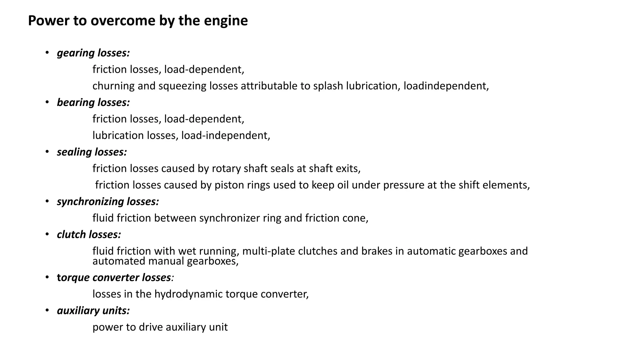
• gearing losses:
frictionlosses, load-dependent,
churning and squeezing losses attributable to splash lubrication, loadindependent,
• bearing losses:
friction losses, load-dependent,
lubrication losses, load-independent,
• sealing losses:
friction losses caused by rotary shaft seals at shaft exits,
friction losses caused by piston rings used to keep oil under pressure at the shift elements,
• synchronizing losses:
fluid friction between synchronizer ring and friction cone,
• clutch losses:
fluid friction with wet running, multi-plate clutches and brakes in automatic gearboxes and
automated manual gearboxes,
• torque converter losses:
losses in the hydrodynamic torque converter,
• auxiliary units:
power to drive auxiliary unit
Power to overcome by the engine
KUCHLE, A., NAUNHEIMER,H., BERTSCHE, B., RYBORZ, J., NOVAK, W. & FIETKAU, P. 2010. Automotive
Transmissions: Fundamentals, Selection, Design and Application, Springer Berlin Heidelberg.
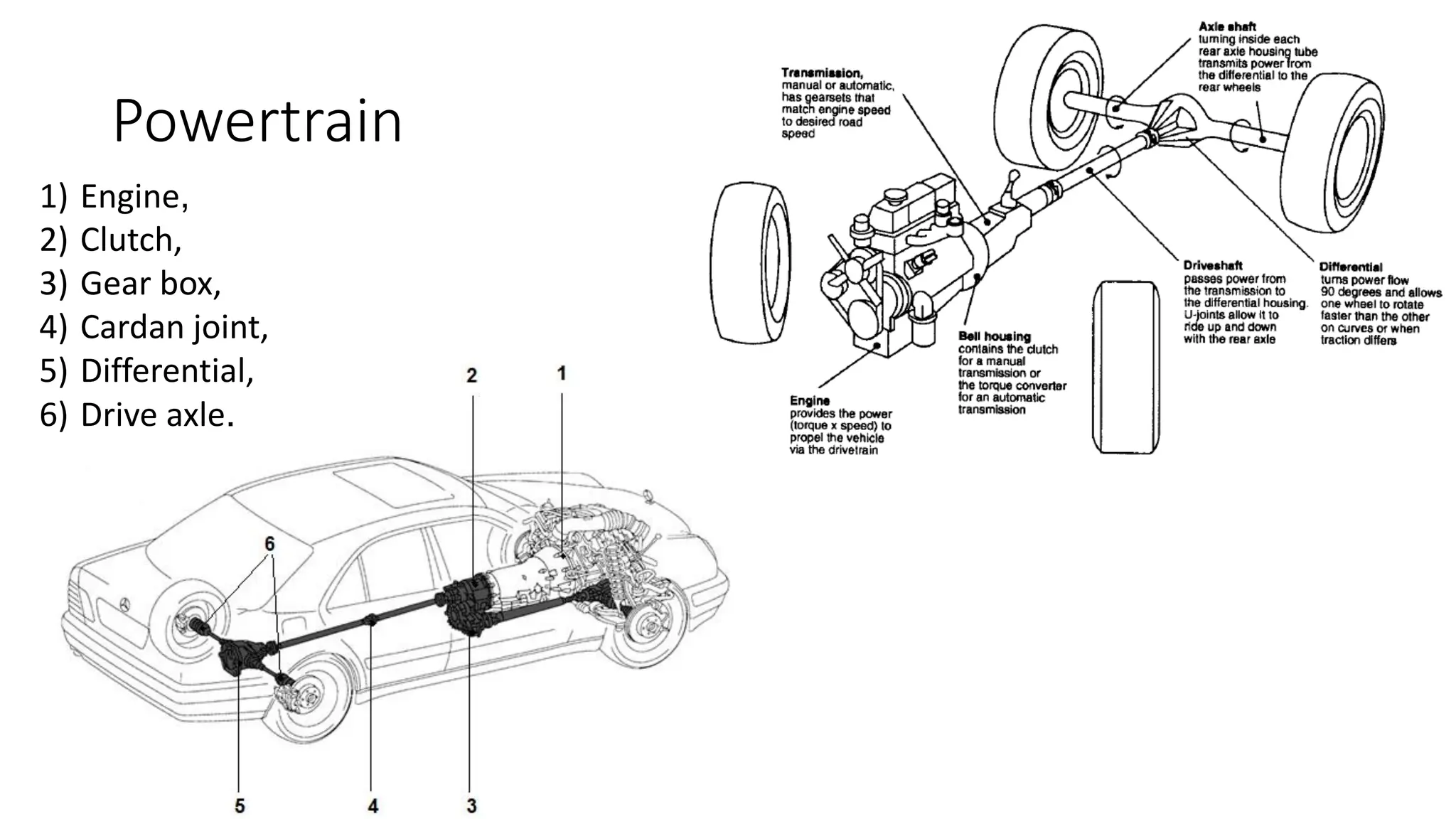
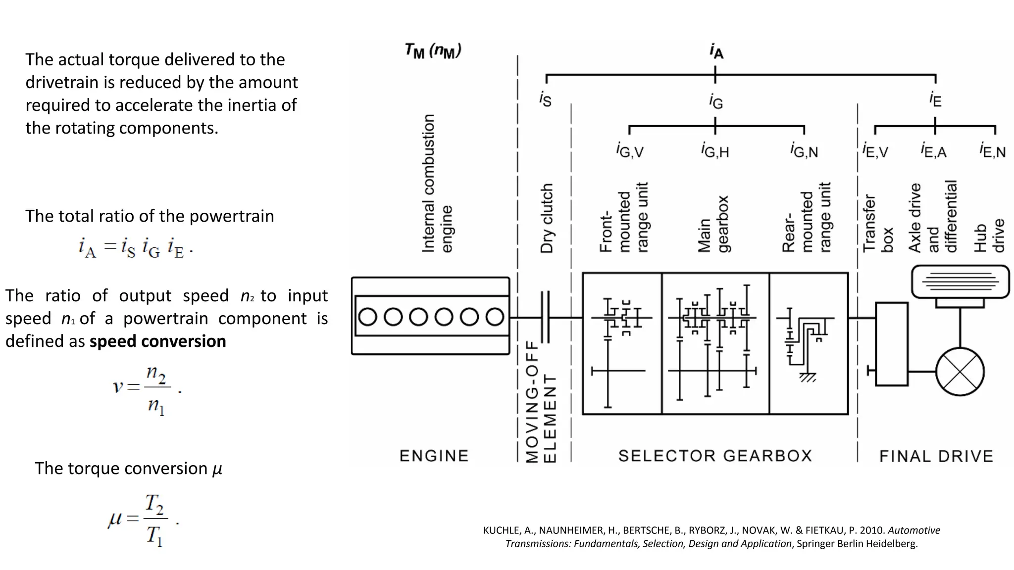
The actual torque delivered to the
drivetrain is reduced by the amount
required to accelerate the inertia of
the rotating components.
The total ratio of the powertrain
The ratio of output speed n2 to input
speed n1 of a powertrain component is
defined as speed conversion
The torque conversion μ
6.
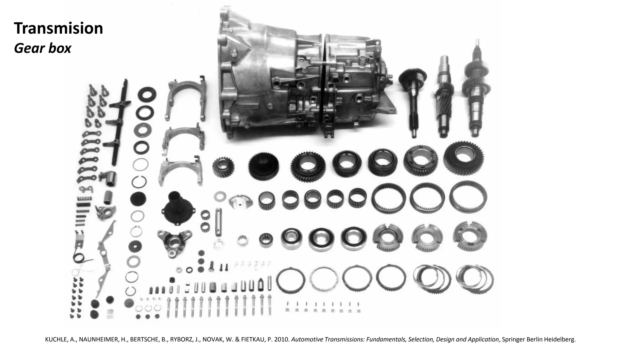
Transmision
Gear box
KUCHLE, A.,NAUNHEIMER, H., BERTSCHE, B., RYBORZ, J., NOVAK, W. & FIETKAU, P. 2010. Automotive Transmissions: Fundamentals, Selection, Design and Application, Springer Berlin Heidelberg.
7.
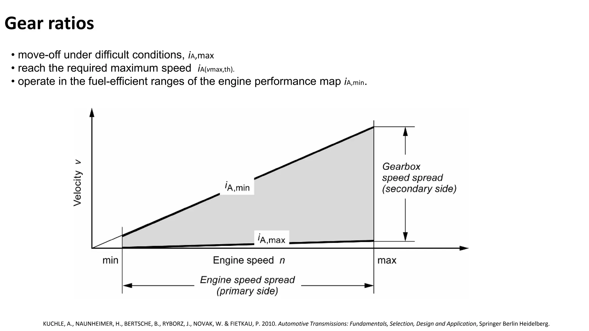
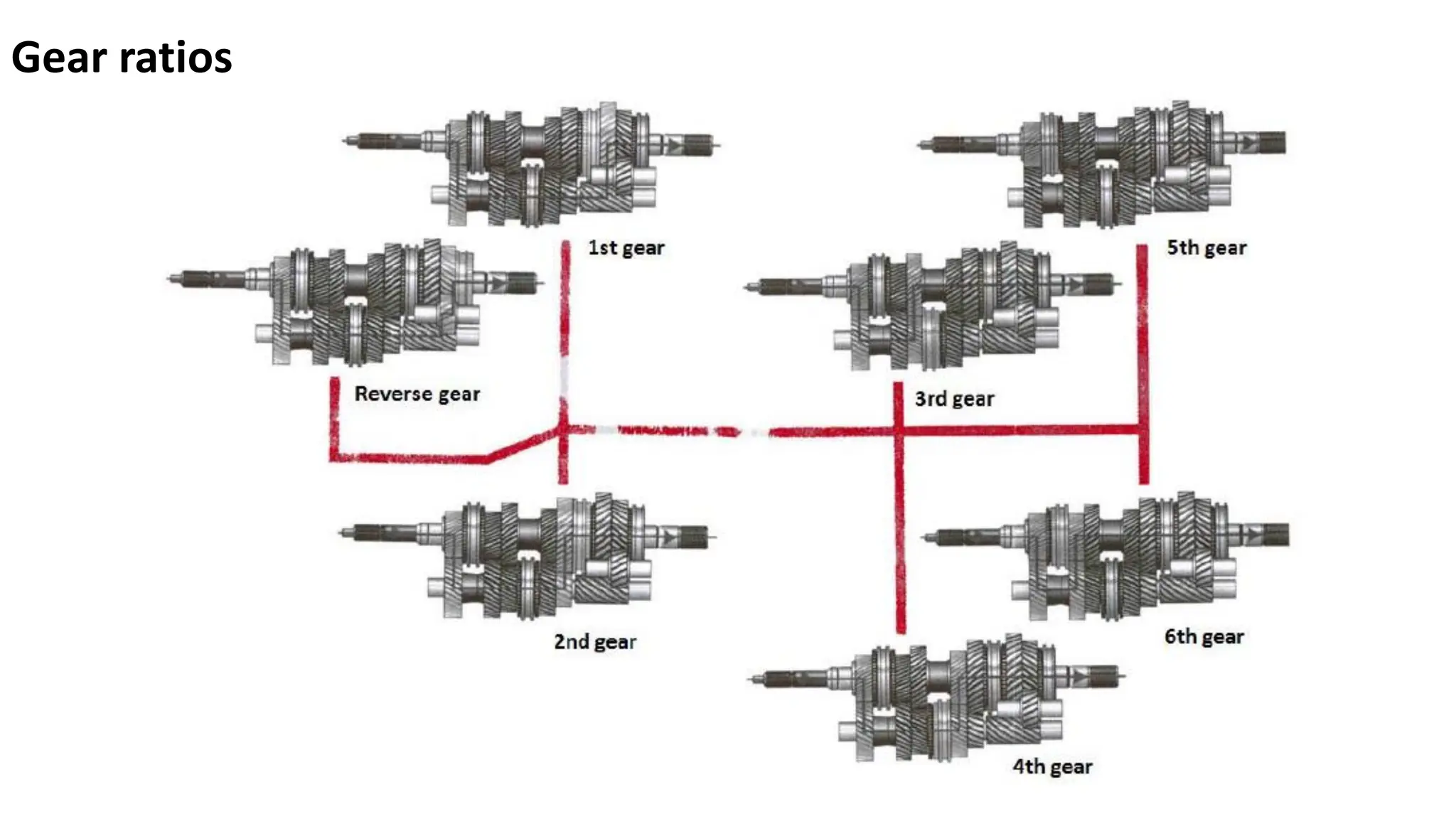
Gear ratios
KUCHLE, A.,NAUNHEIMER, H., BERTSCHE, B., RYBORZ, J., NOVAK, W. & FIETKAU, P. 2010. Automotive Transmissions: Fundamentals, Selection, Design and Application, Springer Berlin Heidelberg.
• move-off under difficult conditions, iA,max
• reach the required maximum speed iA(vmax,th).
• operate in the fuel-efficient ranges of the engine performance map iA,min.
8.
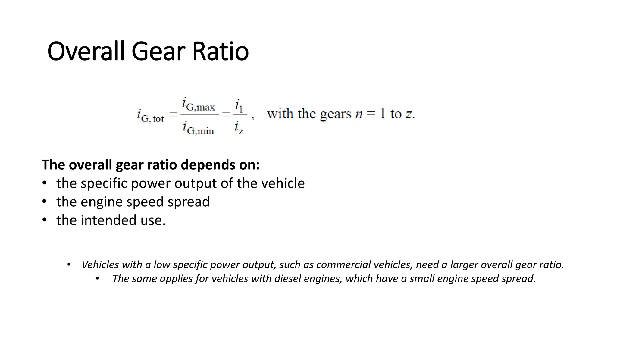
Overall Gear Ratio
•Vehicles with a low specific power output, such as commercial vehicles, need a larger overall gear ratio.
• The same applies for vehicles with diesel engines, which have a small engine speed spread.
The overall gear ratio depends on:
• the specific power output of the vehicle
• the engine speed spread
• the intended use.
9.
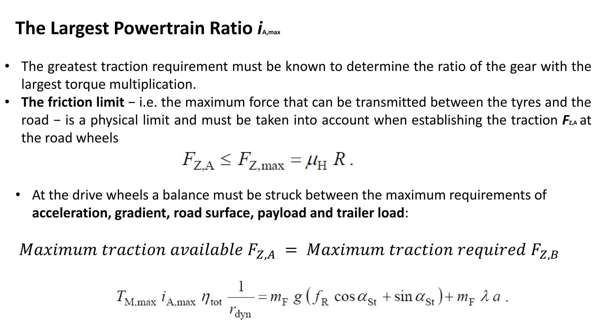
The Largest PowertrainRatio iA,max
• The greatest traction requirement must be known to determine the ratio of the gear with the
largest torque multiplication.
• The friction limit − i.e. the maximum force that can be transmitted between the tyres and the
road − is a physical limit and must be taken into account when establishing the traction FZ,A at
the road wheels
• At the drive wheels a balance must be struck between the maximum requirements of
acceleration, gradient, road surface, payload and trailer load:
𝑀𝑎𝑥𝑖𝑚𝑢𝑚 𝑡𝑟𝑎𝑐𝑡𝑖𝑜𝑛 𝑎𝑣𝑎𝑖𝑙𝑎𝑏𝑙𝑒 𝐹𝑍,𝐴 = 𝑀𝑎𝑥𝑖𝑚𝑢𝑚 𝑡𝑟𝑎𝑐𝑡𝑖𝑜𝑛 𝑟𝑒𝑞𝑢𝑖𝑟𝑒𝑑 𝐹𝑍,𝐵
10.
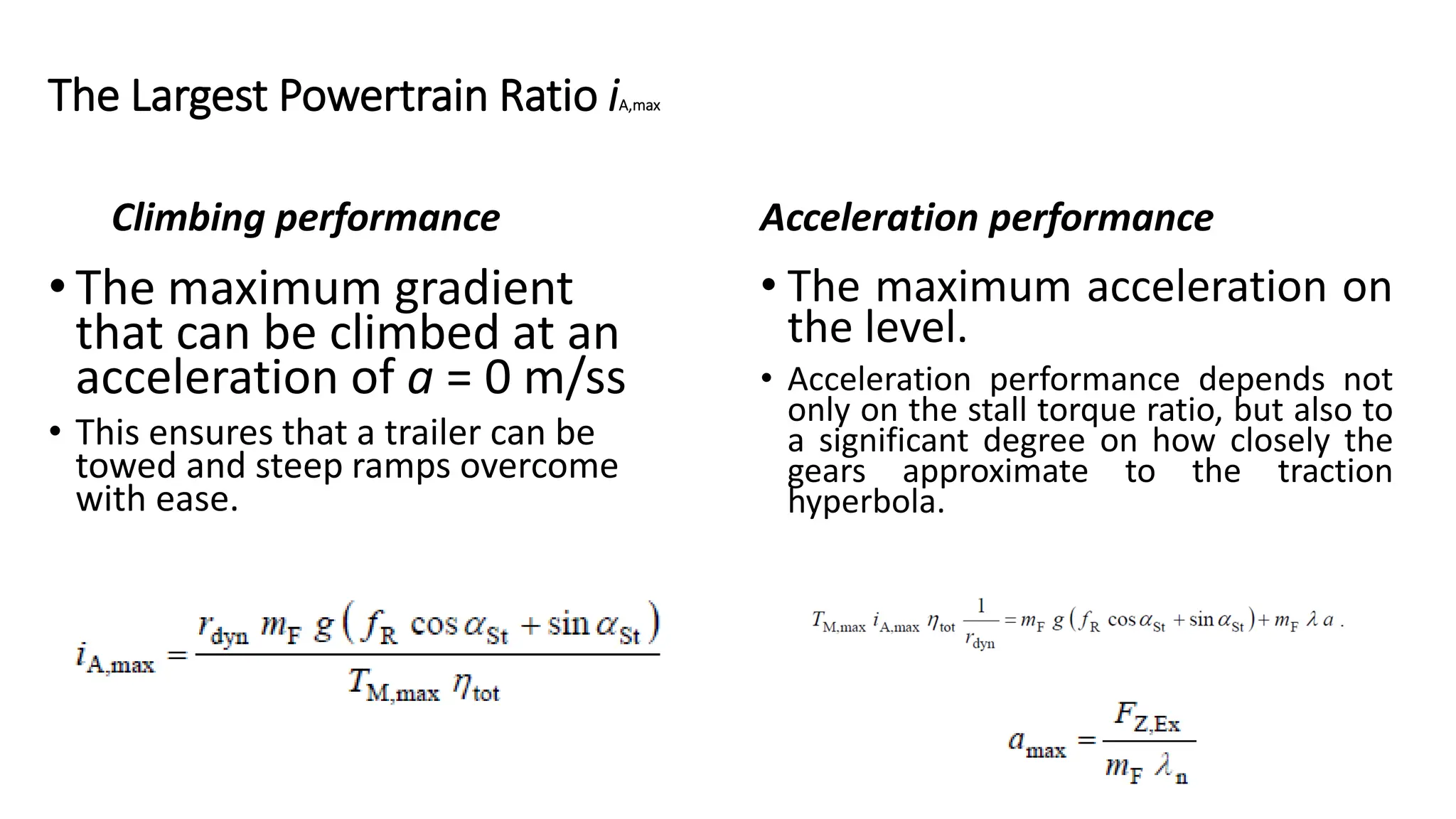
Climbing performance
• Themaximum gradient
that can be climbed at an
acceleration of a = 0 m/ss
• This ensures that a trailer can be
towed and steep ramps overcome
with ease.
Acceleration performance
• The maximum acceleration on
the level.
• Acceleration performance depends not
only on the stall torque ratio, but also to
a significant degree on how closely the
gears approximate to the traction
hyperbola.
The Largest Powertrain Ratio iA,max
11.
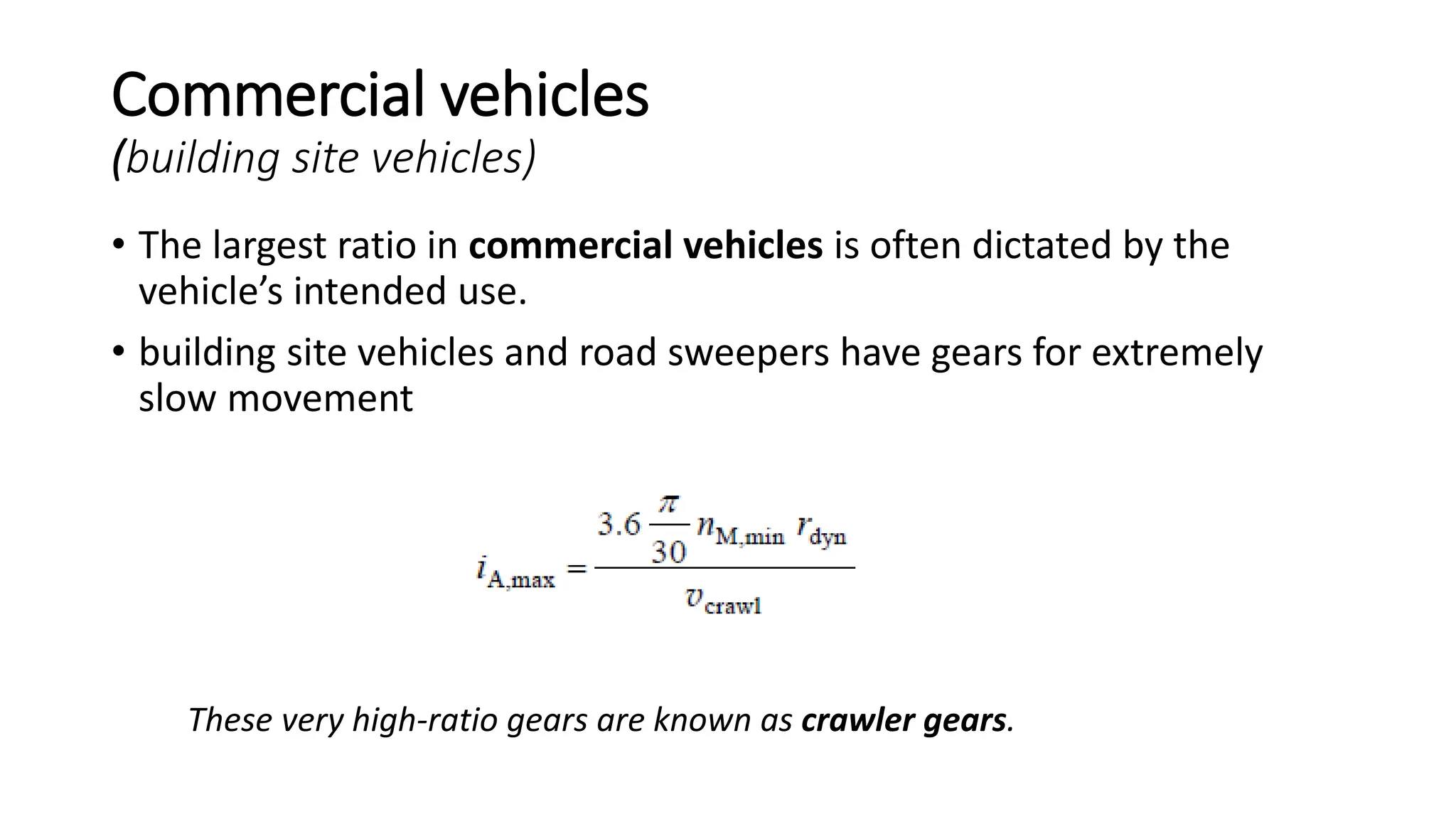
Commercial vehicles
(building sitevehicles)
• The largest ratio in commercial vehicles is often dictated by the
vehicle’s intended use.
• building site vehicles and road sweepers have gears for extremely
slow movement
These very high-ratio gears are known as crawler gears.
12.
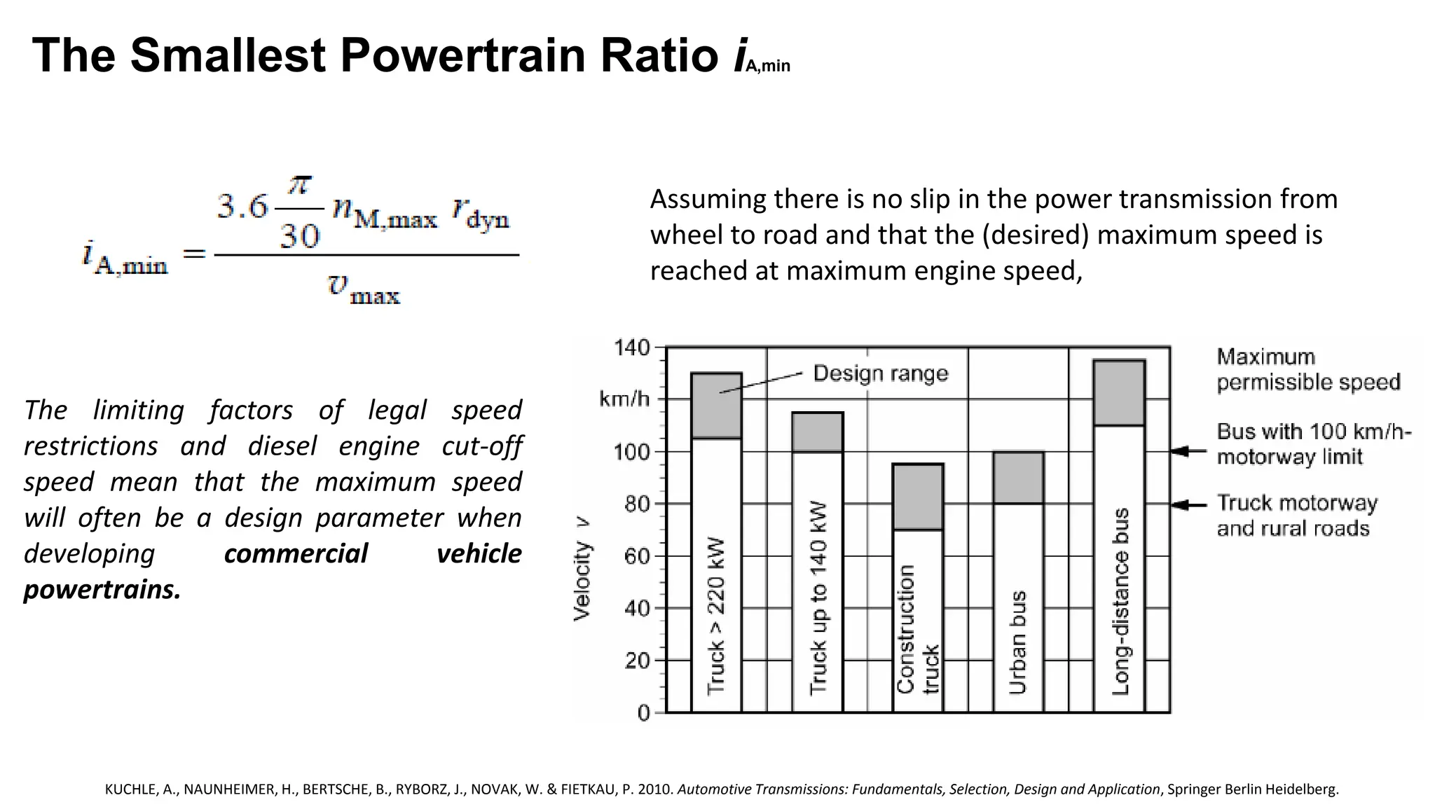
The Smallest PowertrainRatio iA,min
Assuming there is no slip in the power transmission from
wheel to road and that the (desired) maximum speed is
reached at maximum engine speed,
The limiting factors of legal speed
restrictions and diesel engine cut-off
speed mean that the maximum speed
will often be a design parameter when
developing commercial vehicle
powertrains.
KUCHLE, A., NAUNHEIMER, H., BERTSCHE, B., RYBORZ, J., NOVAK, W. & FIETKAU, P. 2010. Automotive Transmissions: Fundamentals, Selection, Design and Application, Springer Berlin Heidelberg.
13.
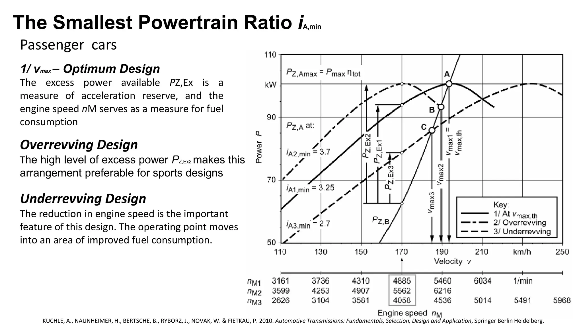
Passenger cars
The SmallestPowertrain Ratio iA,min
KUCHLE, A., NAUNHEIMER, H., BERTSCHE, B., RYBORZ, J., NOVAK, W. & FIETKAU, P. 2010. Automotive Transmissions: Fundamentals, Selection, Design and Application, Springer Berlin Heidelberg.
Overrevving Design
The high level of excess power PZ,Ex2 makes this
arrangement preferable for sports designs
1/ vmax – Optimum Design
The excess power available PZ,Ex is a
measure of acceleration reserve, and the
engine speed nM serves as a measure for fuel
consumption
Underrevving Design
The reduction in engine speed is the important
feature of this design. The operating point moves
into an area of improved fuel consumption.
14.
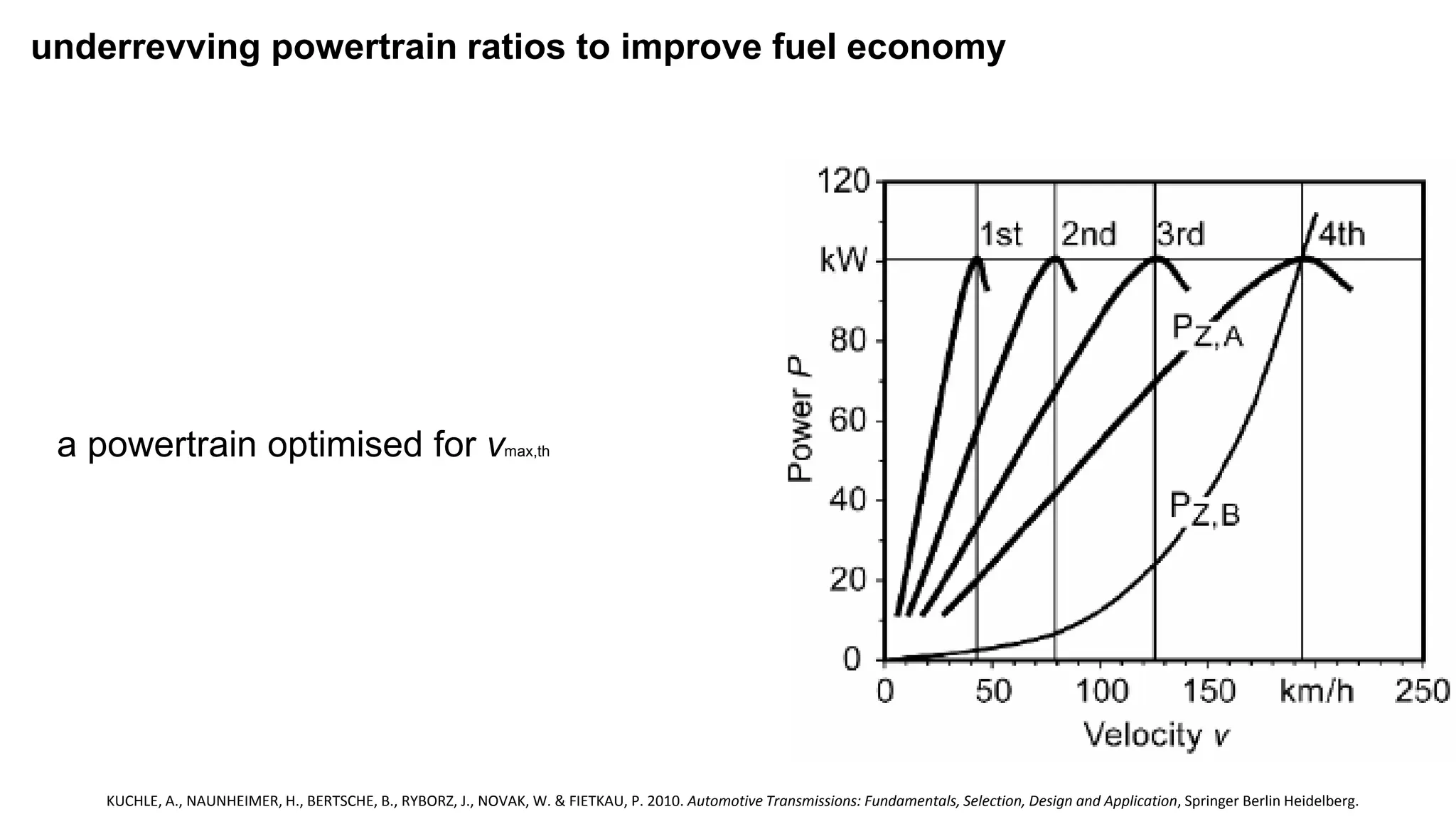
underrevving powertrain ratiosto improve fuel economy
a powertrain optimised for vmax,th
KUCHLE, A., NAUNHEIMER, H., BERTSCHE, B., RYBORZ, J., NOVAK, W. & FIETKAU, P. 2010. Automotive Transmissions: Fundamentals, Selection, Design and Application, Springer Berlin Heidelberg.
15.
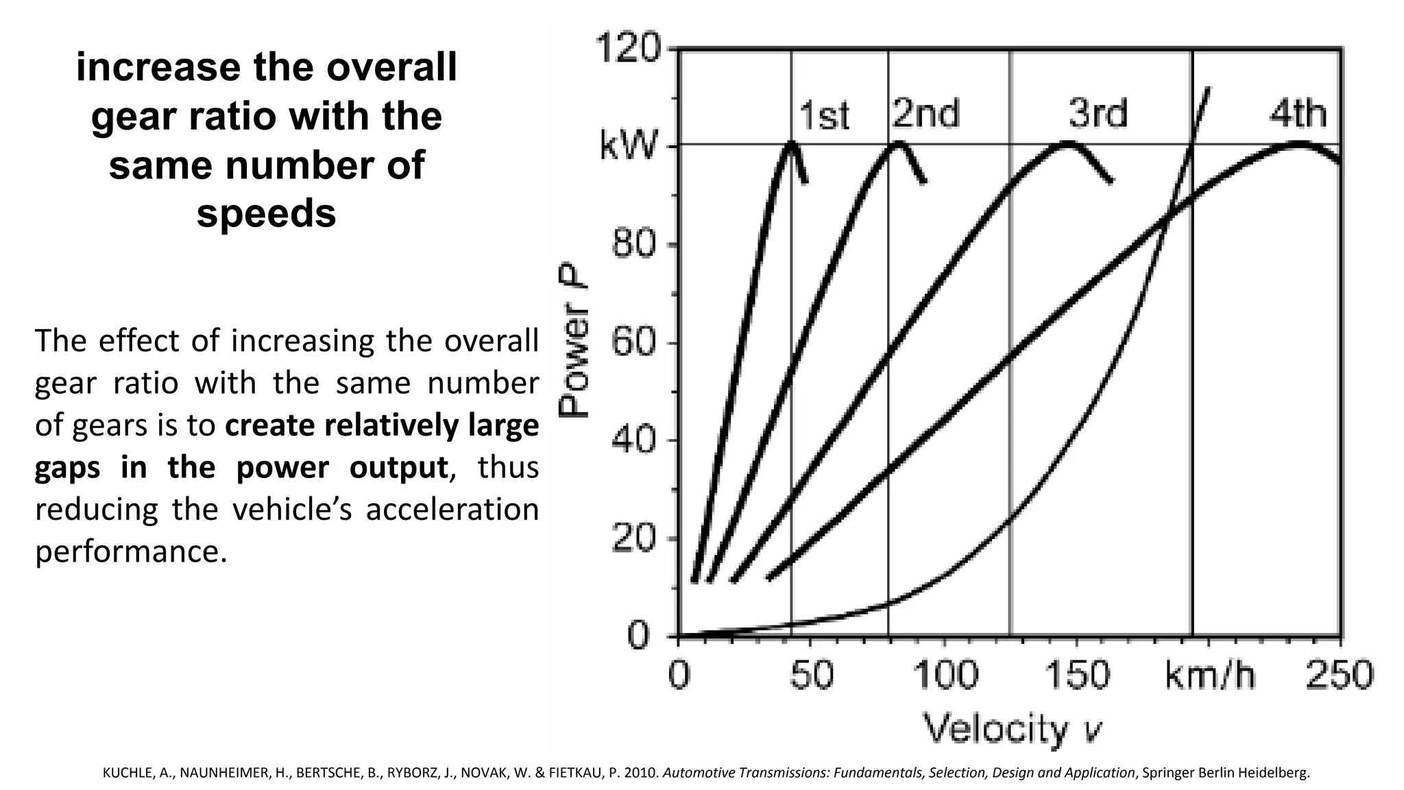
increase the overall
gearratio with the
same number of
speeds
The effect of increasing the overall
gear ratio with the same number
of gears is to create relatively large
gaps in the power output, thus
reducing the vehicle’s acceleration
performance.
KUCHLE, A., NAUNHEIMER, H., BERTSCHE, B., RYBORZ, J., NOVAK, W. & FIETKAU, P. 2010. Automotive Transmissions: Fundamentals, Selection, Design and Application, Springer Berlin Heidelberg.
16.
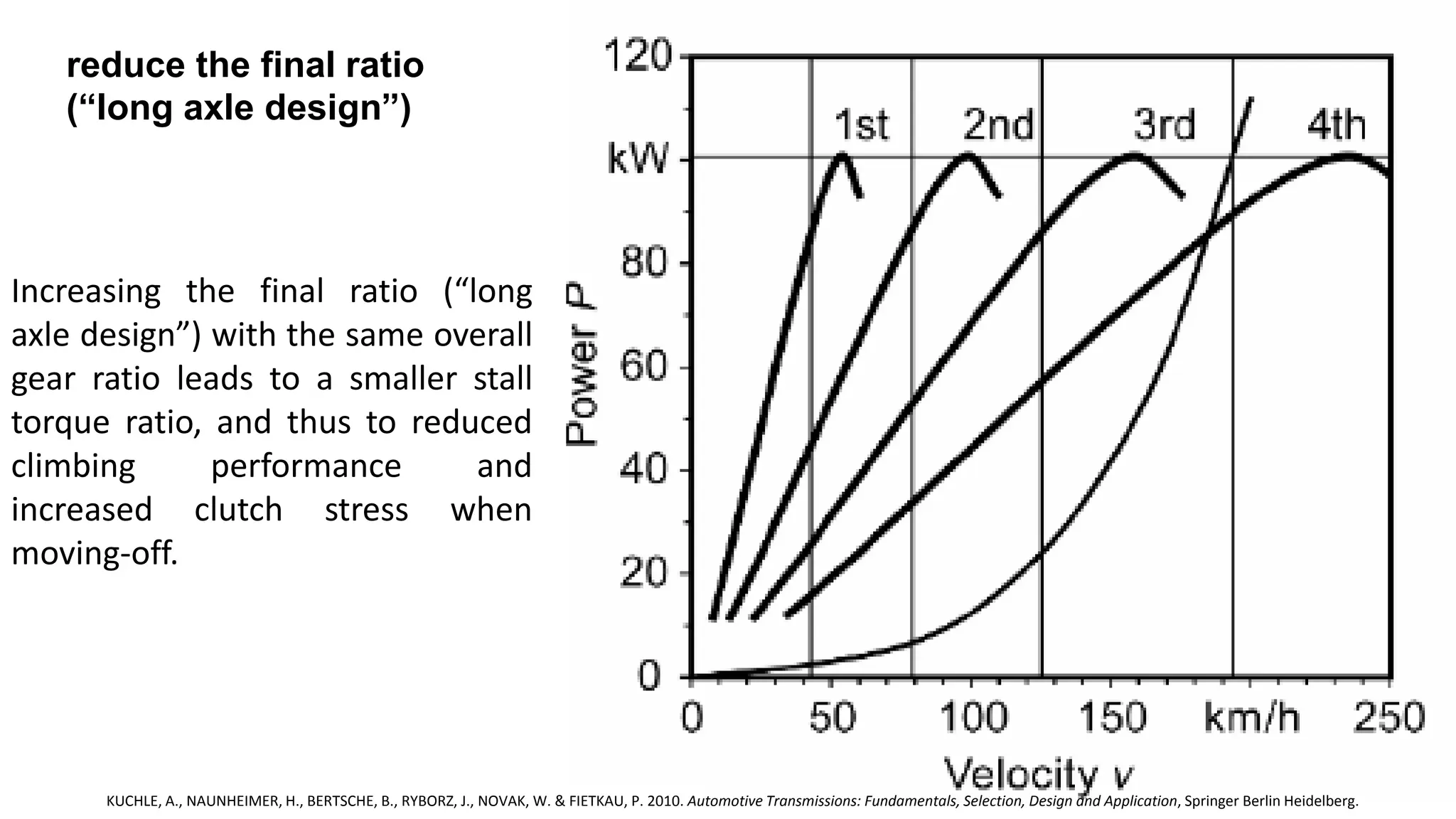
reduce the finalratio
(“long axle design”)
Increasing the final ratio (“long
axle design”) with the same overall
gear ratio leads to a smaller stall
torque ratio, and thus to reduced
climbing performance and
increased clutch stress when
moving-off.
KUCHLE, A., NAUNHEIMER, H., BERTSCHE, B., RYBORZ, J., NOVAK, W. & FIETKAU, P. 2010. Automotive Transmissions: Fundamentals, Selection, Design and Application, Springer Berlin Heidelberg.
17.
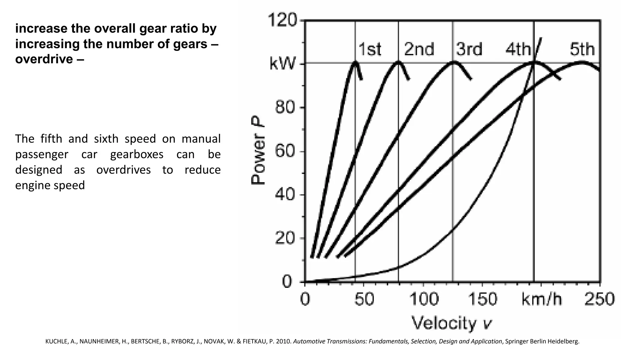
increase the overallgear ratio by
increasing the number of gears –
overdrive –
The fifth and sixth speed on manual
passenger car gearboxes can be
designed as overdrives to reduce
engine speed
KUCHLE, A., NAUNHEIMER, H., BERTSCHE, B., RYBORZ, J., NOVAK, W. & FIETKAU, P. 2010. Automotive Transmissions: Fundamentals, Selection, Design and Application, Springer Berlin Heidelberg.
18.
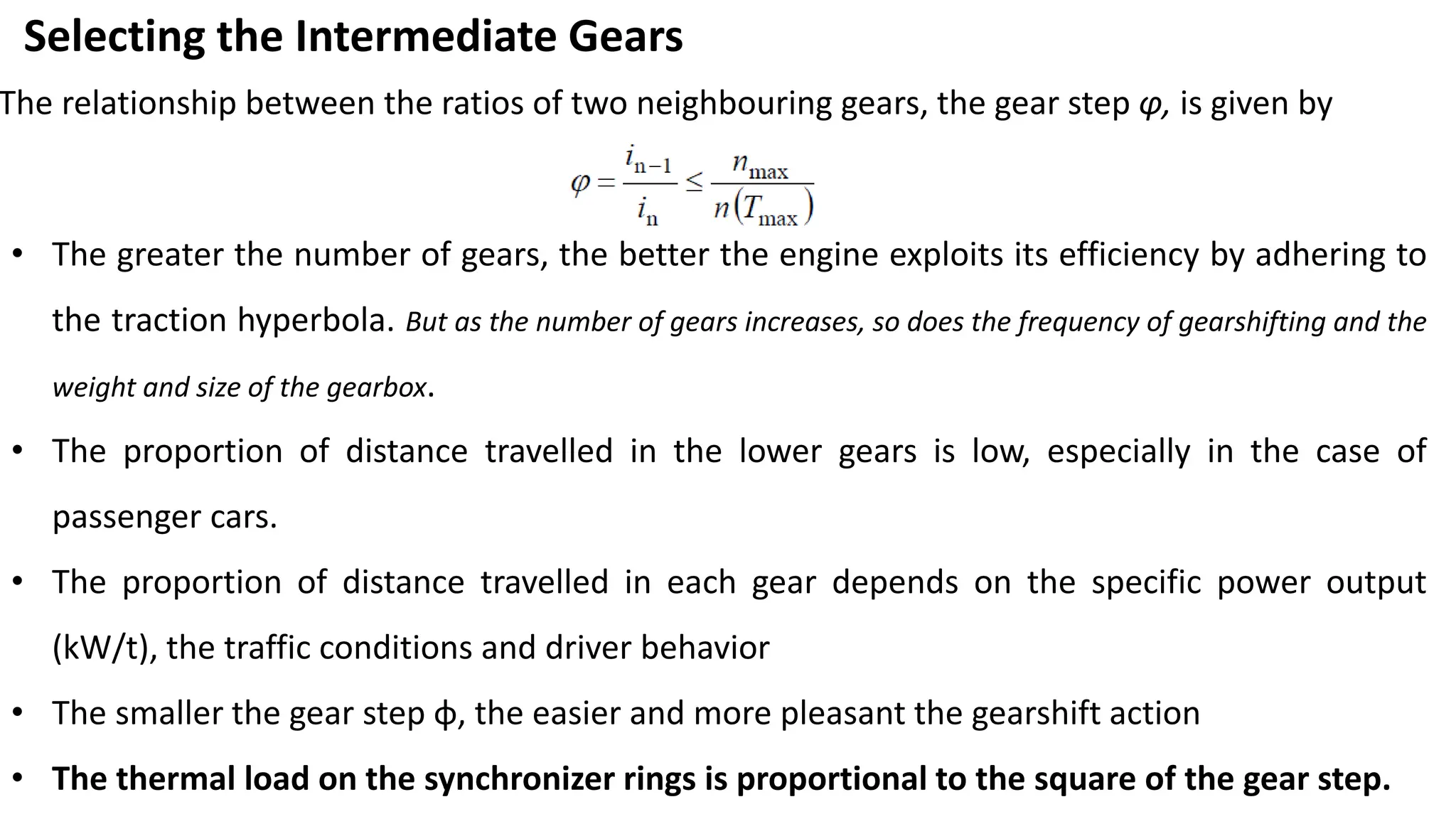
Selecting the IntermediateGears
The relationship between the ratios of two neighbouring gears, the gear step φ, is given by
• The greater the number of gears, the better the engine exploits its efficiency by adhering to
the traction hyperbola. But as the number of gears increases, so does the frequency of gearshifting and the
weight and size of the gearbox.
• The proportion of distance travelled in the lower gears is low, especially in the case of
passenger cars.
• The proportion of distance travelled in each gear depends on the specific power output
(kW/t), the traffic conditions and driver behavior
• The smaller the gear step φ, the easier and more pleasant the gearshift action
• The thermal load on the synchronizer rings is proportional to the square of the gear step.
19.
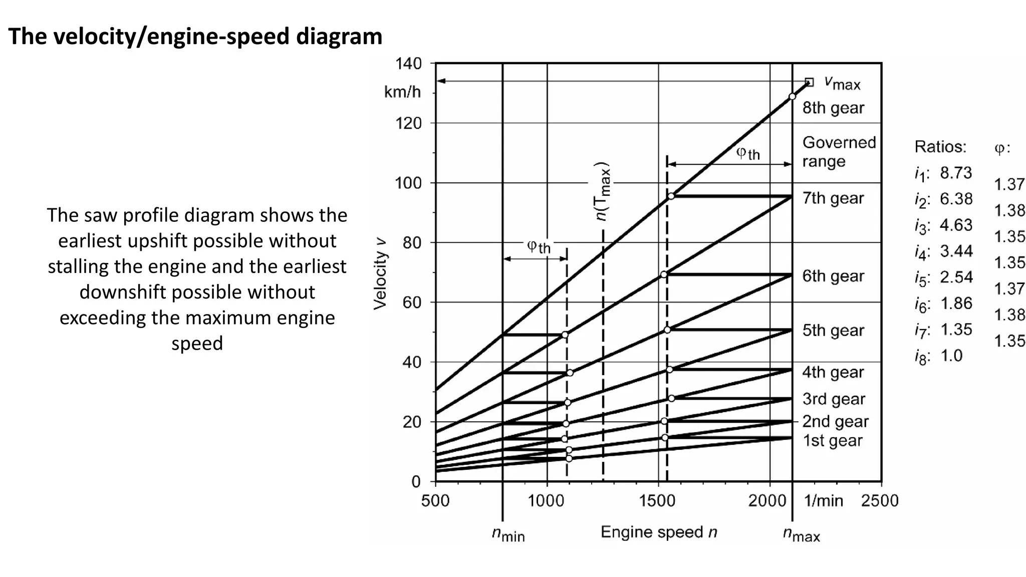
The velocity/engine-speed diagram
Thesaw profile diagram shows the
earliest upshift possible without
stalling the engine and the earliest
downshift possible without
exceeding the maximum engine
speed
20.
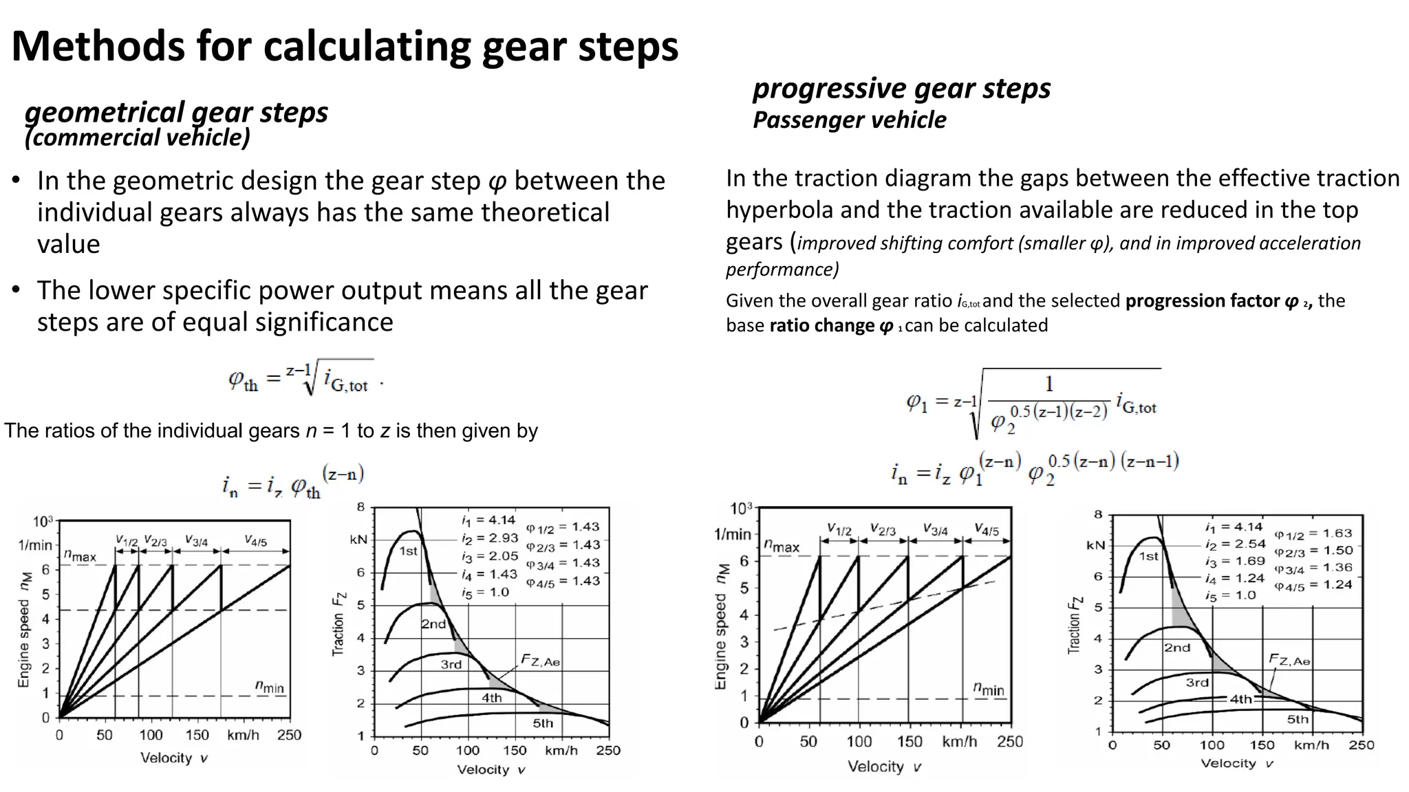
Methods for calculatinggear steps
geometrical gear steps
(commercial vehicle)
• In the geometric design the gear step φ between the
individual gears always has the same theoretical
value
• The lower specific power output means all the gear
steps are of equal significance
progressive gear steps
Passenger vehicle
The ratios of the individual gears n = 1 to z is then given by
In the traction diagram the gaps between the effective traction
hyperbola and the traction available are reduced in the top
gears (improved shifting comfort (smaller φ), and in improved acceleration
performance)
Given the overall gear ratio iG,tot and the selected progression factor φ 2, the
base ratio change φ 1 can be calculated
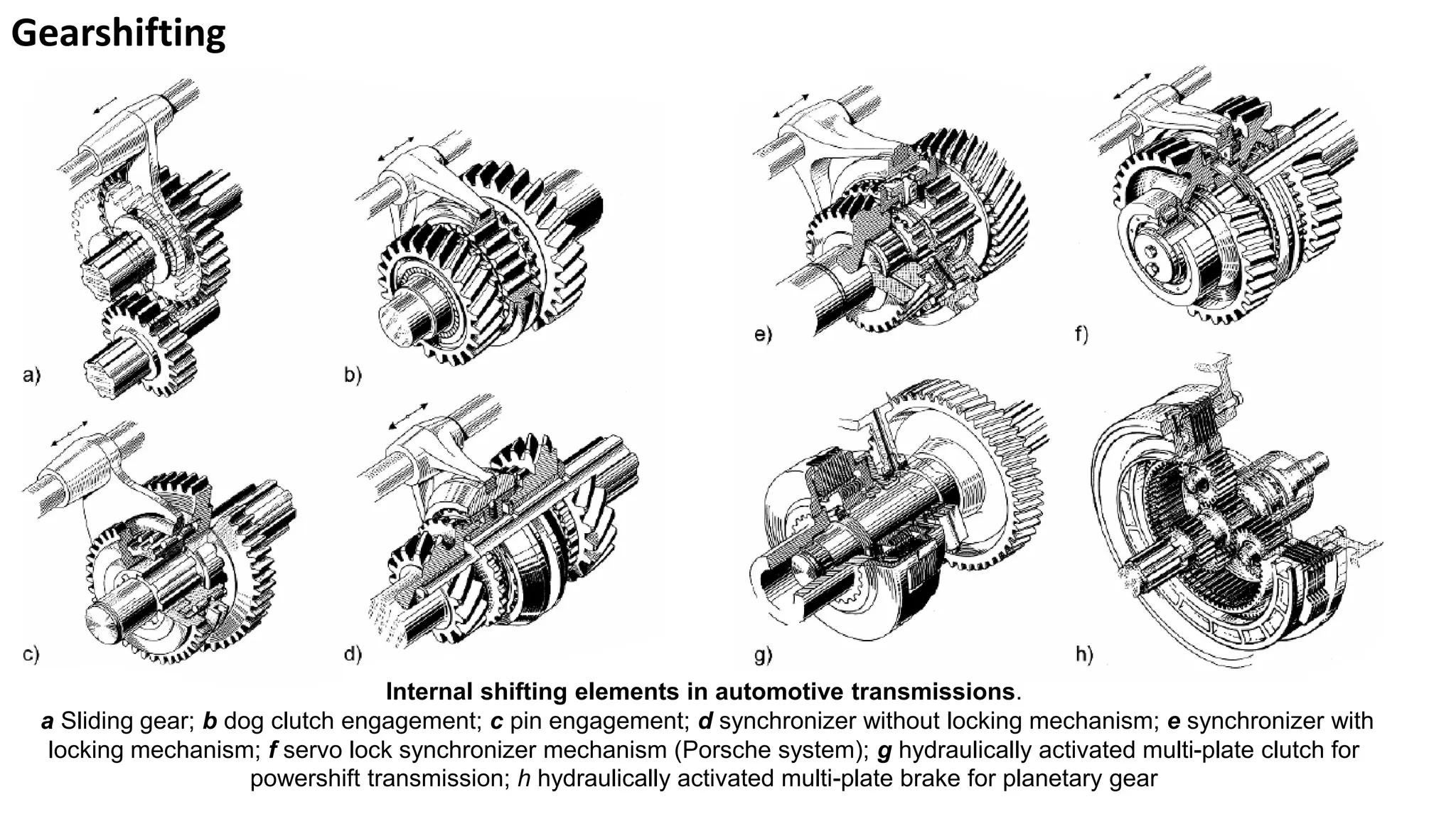
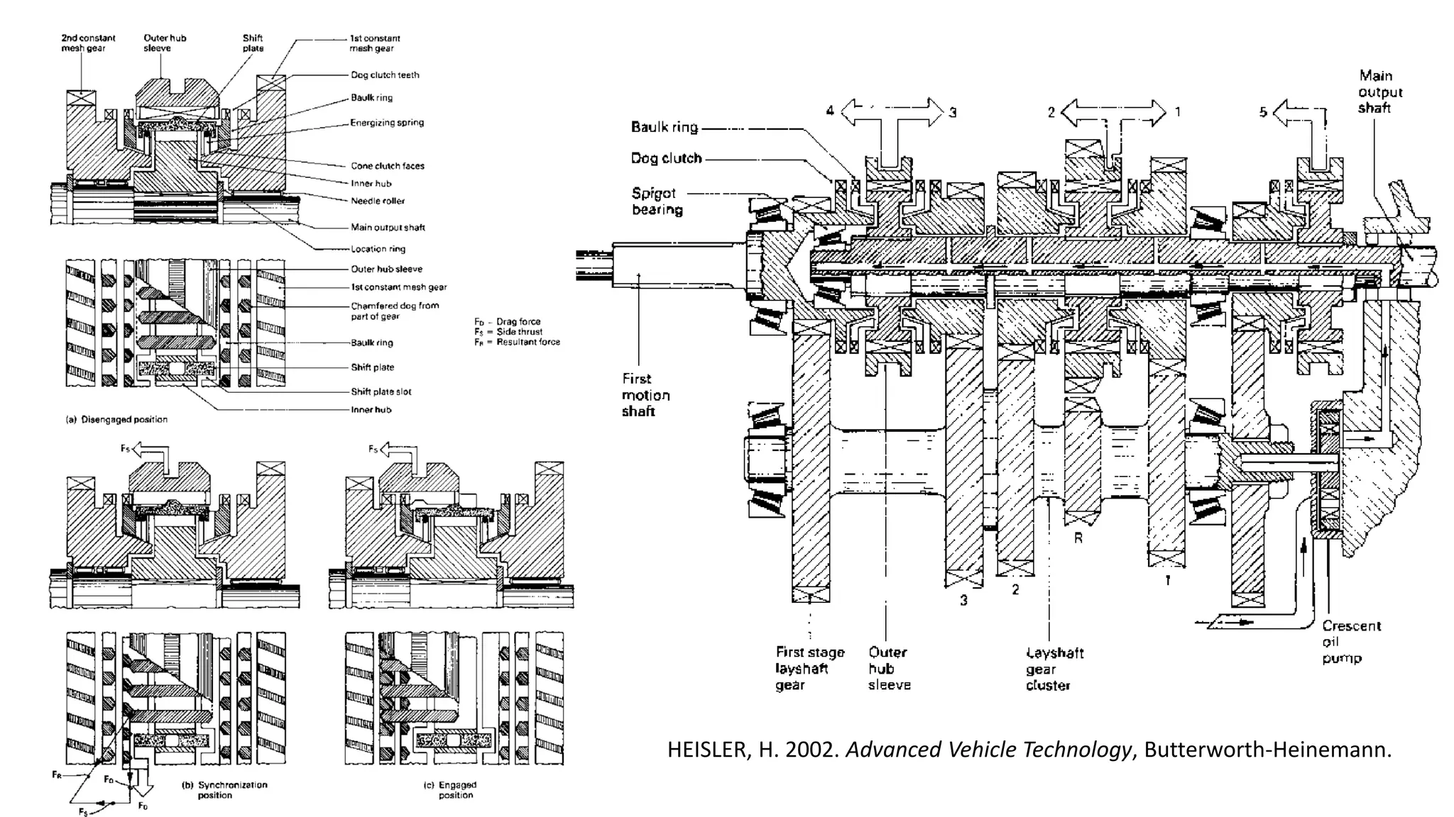
Gearshifting
Internal shifting elementsin automotive transmissions.
a Sliding gear; b dog clutch engagement; c pin engagement; d synchronizer without locking mechanism; e synchronizer with
locking mechanism; f servo lock synchronizer mechanism (Porsche system); g hydraulically activated multi-plate clutch for
powershift transmission; h hydraulically activated multi-plate brake for planetary gear
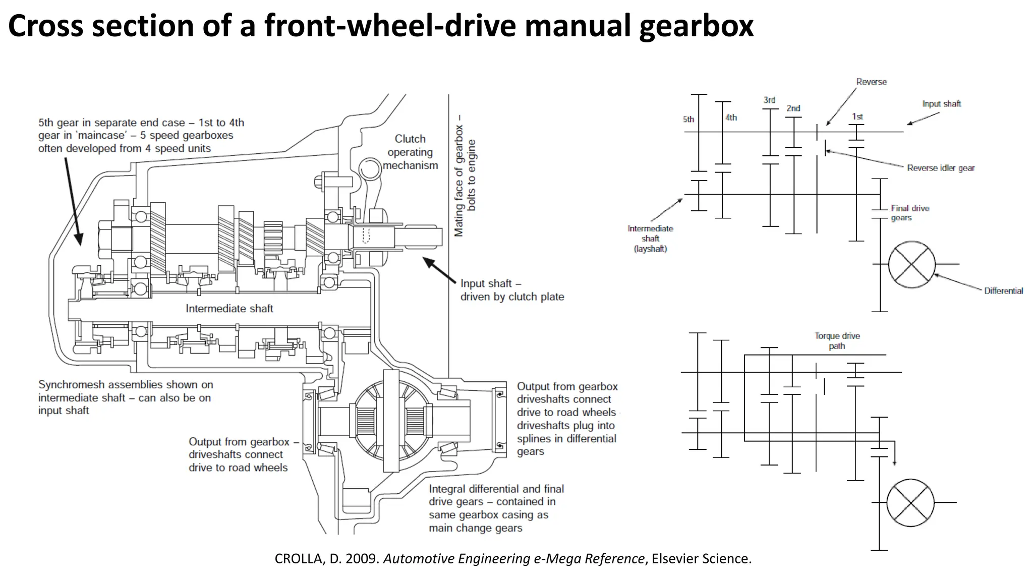
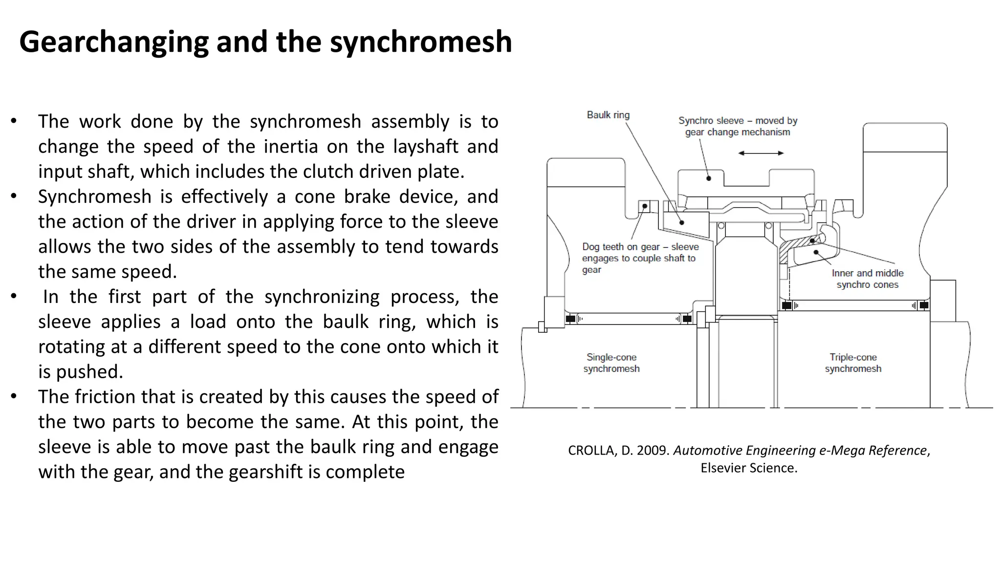
Gearchanging and thesynchromesh
• The work done by the synchromesh assembly is to
change the speed of the inertia on the layshaft and
input shaft, which includes the clutch driven plate.
• Synchromesh is effectively a cone brake device, and
the action of the driver in applying force to the sleeve
allows the two sides of the assembly to tend towards
the same speed.
• In the first part of the synchronizing process, the
sleeve applies a load onto the baulk ring, which is
rotating at a different speed to the cone onto which it
is pushed.
• The friction that is created by this causes the speed of
the two parts to become the same. At this point, the
sleeve is able to move past the baulk ring and engage
with the gear, and the gearshift is complete
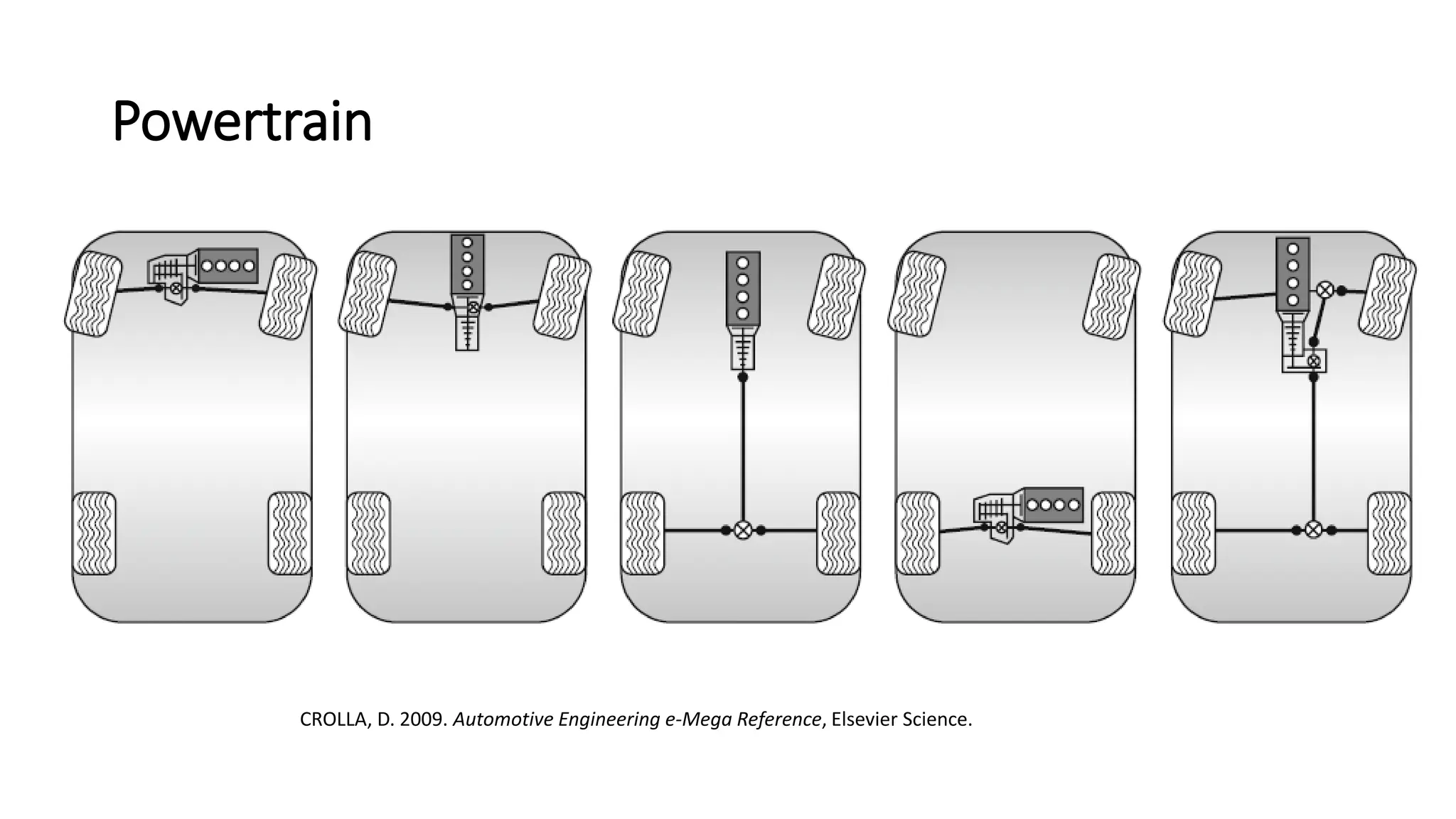
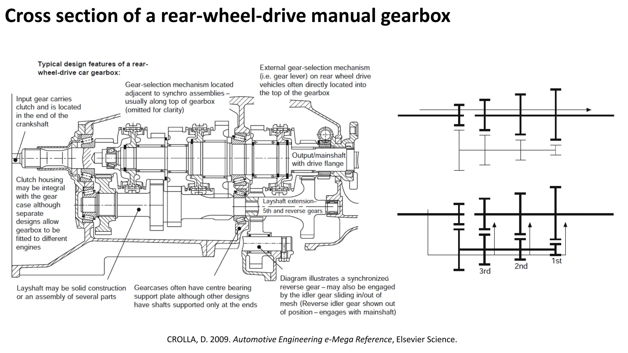
CROLLA, D. 2009. Automotive Engineering e-Mega Reference,
Elsevier Science.
26.
HEISLER, H. 2002.Advanced Vehicle Technology, Butterworth-Heinemann.
27.
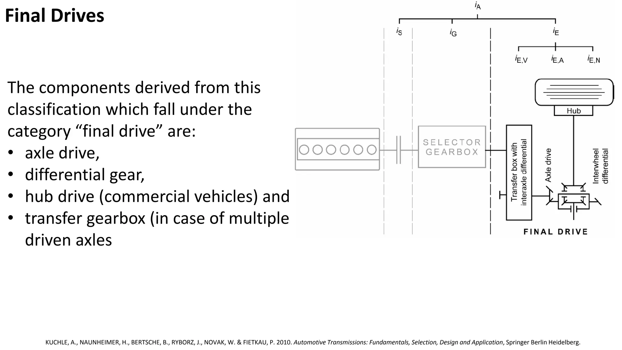
Final Drives
KUCHLE, A.,NAUNHEIMER, H., BERTSCHE, B., RYBORZ, J., NOVAK, W. & FIETKAU, P. 2010. Automotive Transmissions: Fundamentals, Selection, Design and Application, Springer Berlin Heidelberg.
The components derived from this
classification which fall under the
category “final drive” are:
• axle drive,
• differential gear,
• hub drive (commercial vehicles) and
• transfer gearbox (in case of multiple
driven axles
28.
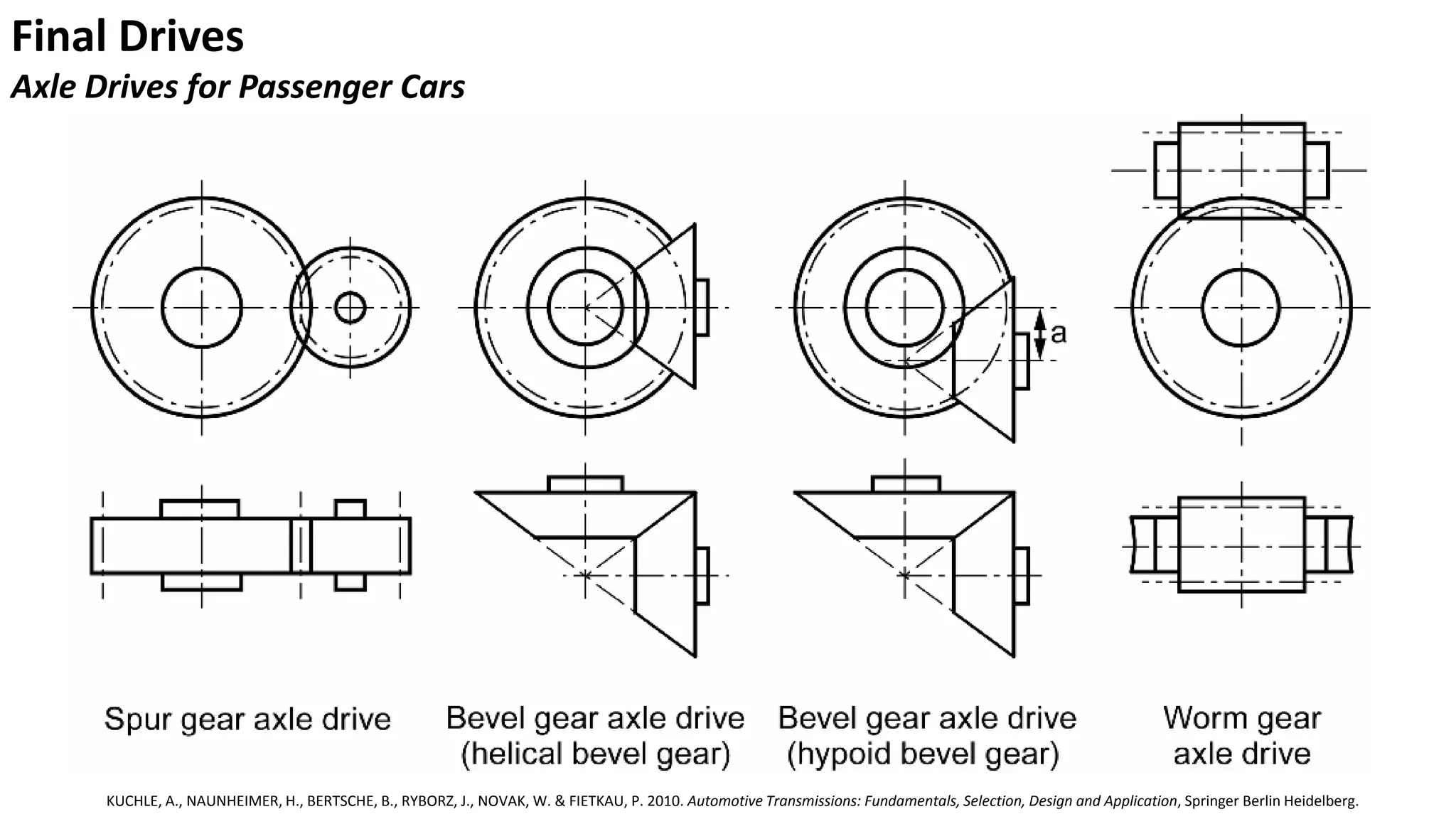
Final Drives
Axle Drivesfor Passenger Cars
KUCHLE, A., NAUNHEIMER, H., BERTSCHE, B., RYBORZ, J., NOVAK, W. & FIETKAU, P. 2010. Automotive Transmissions: Fundamentals, Selection, Design and Application, Springer Berlin Heidelberg.
29.
Final Drives
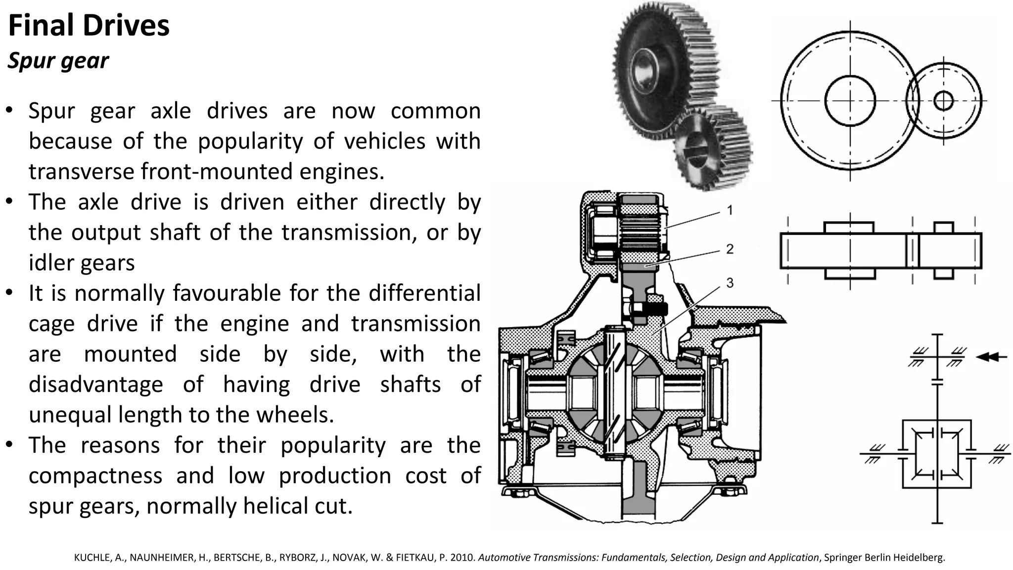
Spur gear
•Spur gear axle drives are now common
because of the popularity of vehicles with
transverse front-mounted engines.
• The axle drive is driven either directly by
the output shaft of the transmission, or by
idler gears
• It is normally favourable for the differential
cage drive if the engine and transmission
are mounted side by side, with the
disadvantage of having drive shafts of
unequal length to the wheels.
• The reasons for their popularity are the
compactness and low production cost of
spur gears, normally helical cut.
KUCHLE, A., NAUNHEIMER, H., BERTSCHE, B., RYBORZ, J., NOVAK, W. & FIETKAU, P. 2010. Automotive Transmissions: Fundamentals, Selection, Design and Application, Springer Berlin Heidelberg.
30.
Final Drives
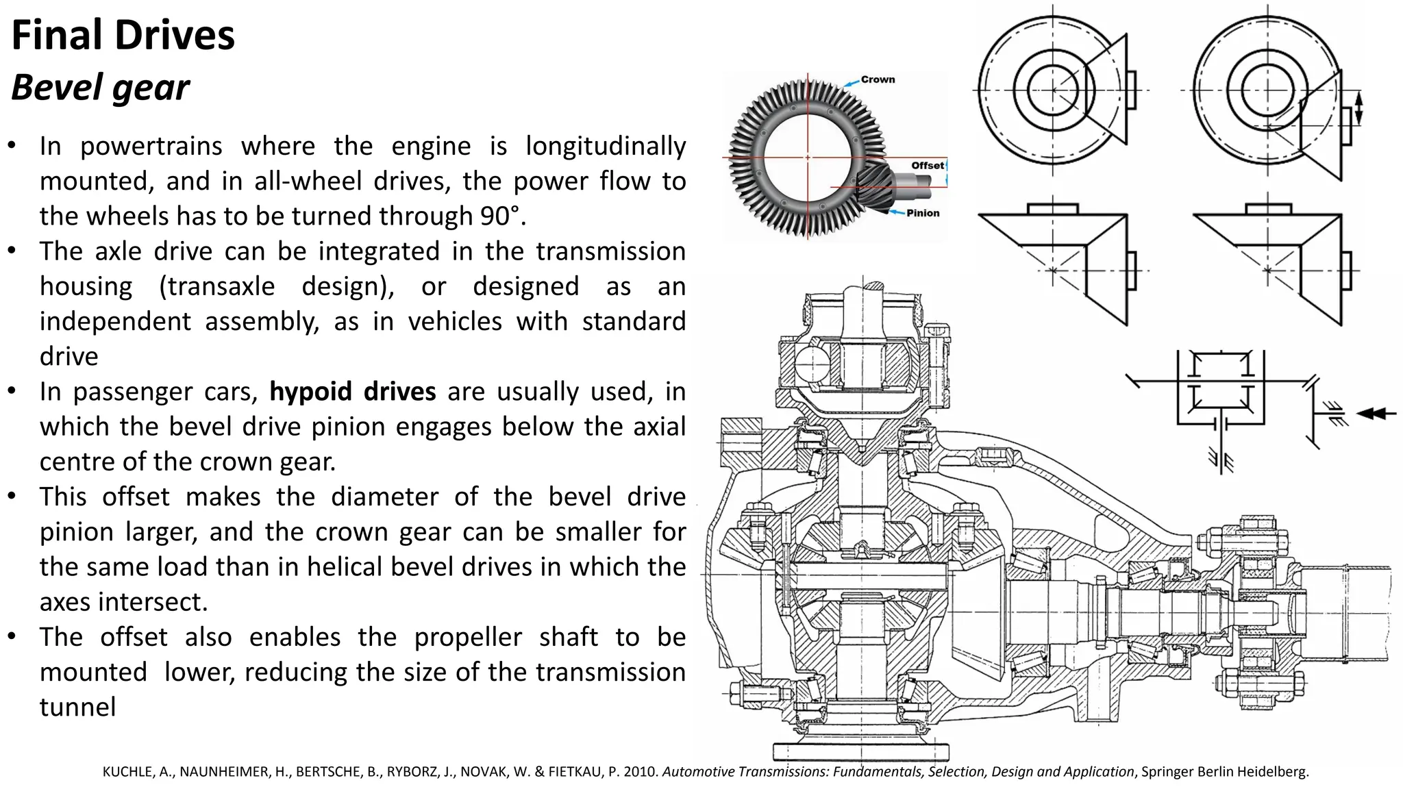
Bevel gear
•In powertrains where the engine is longitudinally
mounted, and in all-wheel drives, the power flow to
the wheels has to be turned through 90°.
• The axle drive can be integrated in the transmission
housing (transaxle design), or designed as an
independent assembly, as in vehicles with standard
drive
• In passenger cars, hypoid drives are usually used, in
which the bevel drive pinion engages below the axial
centre of the crown gear.
• This offset makes the diameter of the bevel drive
pinion larger, and the crown gear can be smaller for
the same load than in helical bevel drives in which the
axes intersect.
• The offset also enables the propeller shaft to be
mounted lower, reducing the size of the transmission
tunnel
KUCHLE, A., NAUNHEIMER, H., BERTSCHE, B., RYBORZ, J., NOVAK, W. & FIETKAU, P. 2010. Automotive Transmissions: Fundamentals, Selection, Design and Application, Springer Berlin Heidelberg.
31.
Final Drives
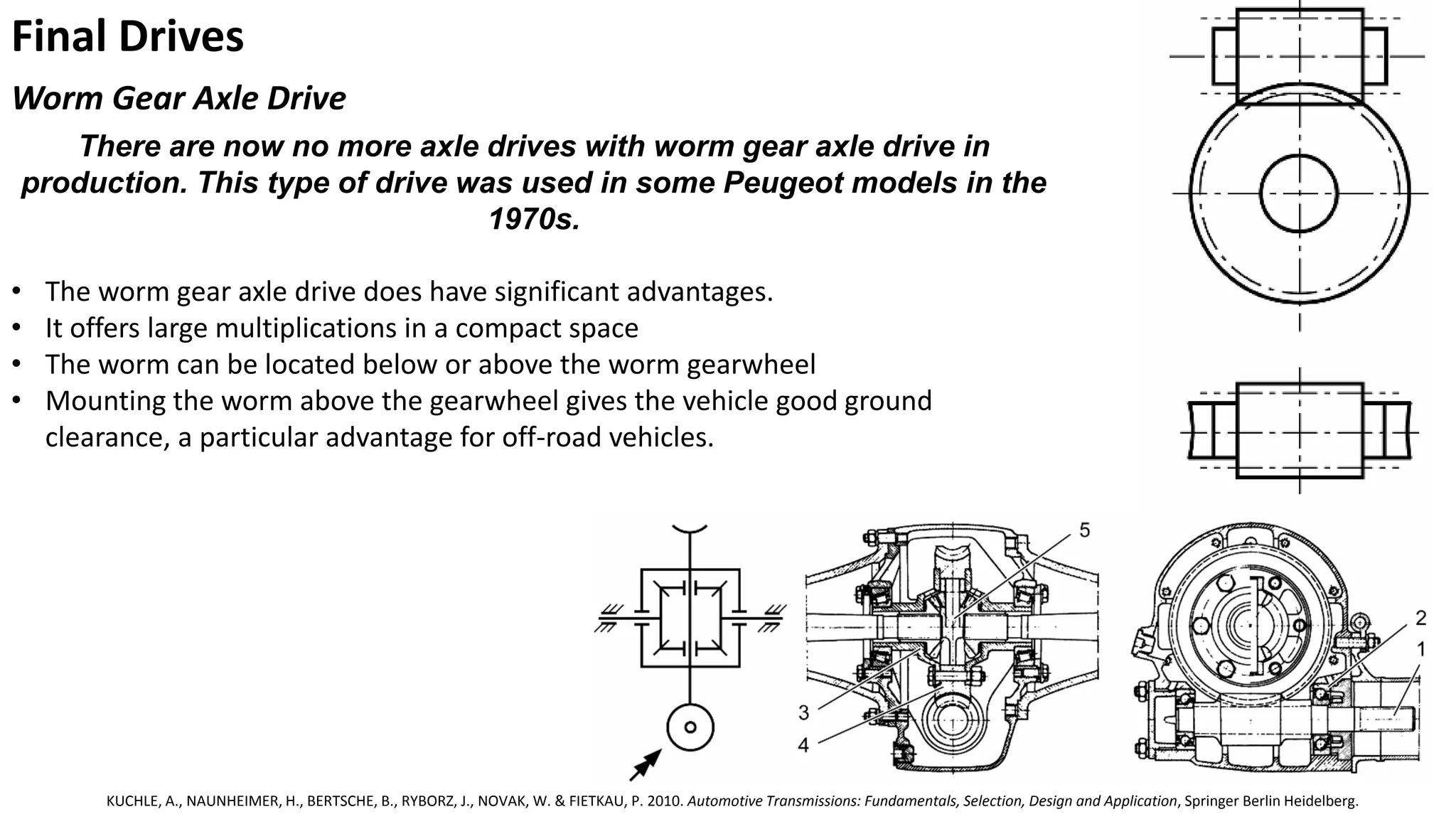
Worm GearAxle Drive
There are now no more axle drives with worm gear axle drive in
production. This type of drive was used in some Peugeot models in the
1970s.
• The worm gear axle drive does have significant advantages.
• It offers large multiplications in a compact space
• The worm can be located below or above the worm gearwheel
• Mounting the worm above the gearwheel gives the vehicle good ground
clearance, a particular advantage for off-road vehicles.
KUCHLE, A., NAUNHEIMER, H., BERTSCHE, B., RYBORZ, J., NOVAK, W. & FIETKAU, P. 2010. Automotive Transmissions: Fundamentals, Selection, Design and Application, Springer Berlin Heidelberg.
32.
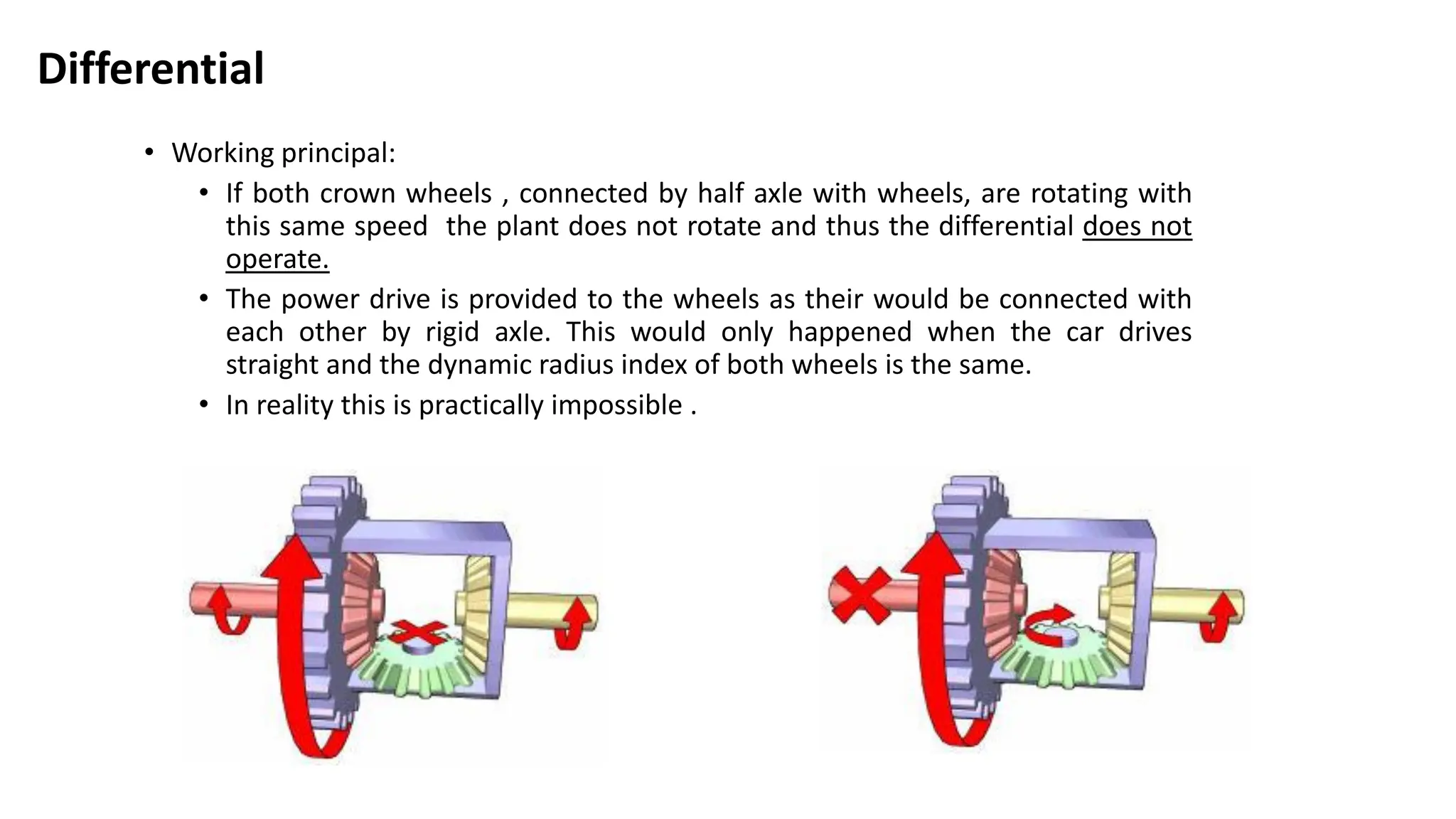
Differential
• Working principal:
•If both crown wheels , connected by half axle with wheels, are rotating with
this same speed the plant does not rotate and thus the differential does not
operate.
• The power drive is provided to the wheels as their would be connected with
each other by rigid axle. This would only happened when the car drives
straight and the dynamic radius index of both wheels is the same.
• In reality this is practically impossible .
33.
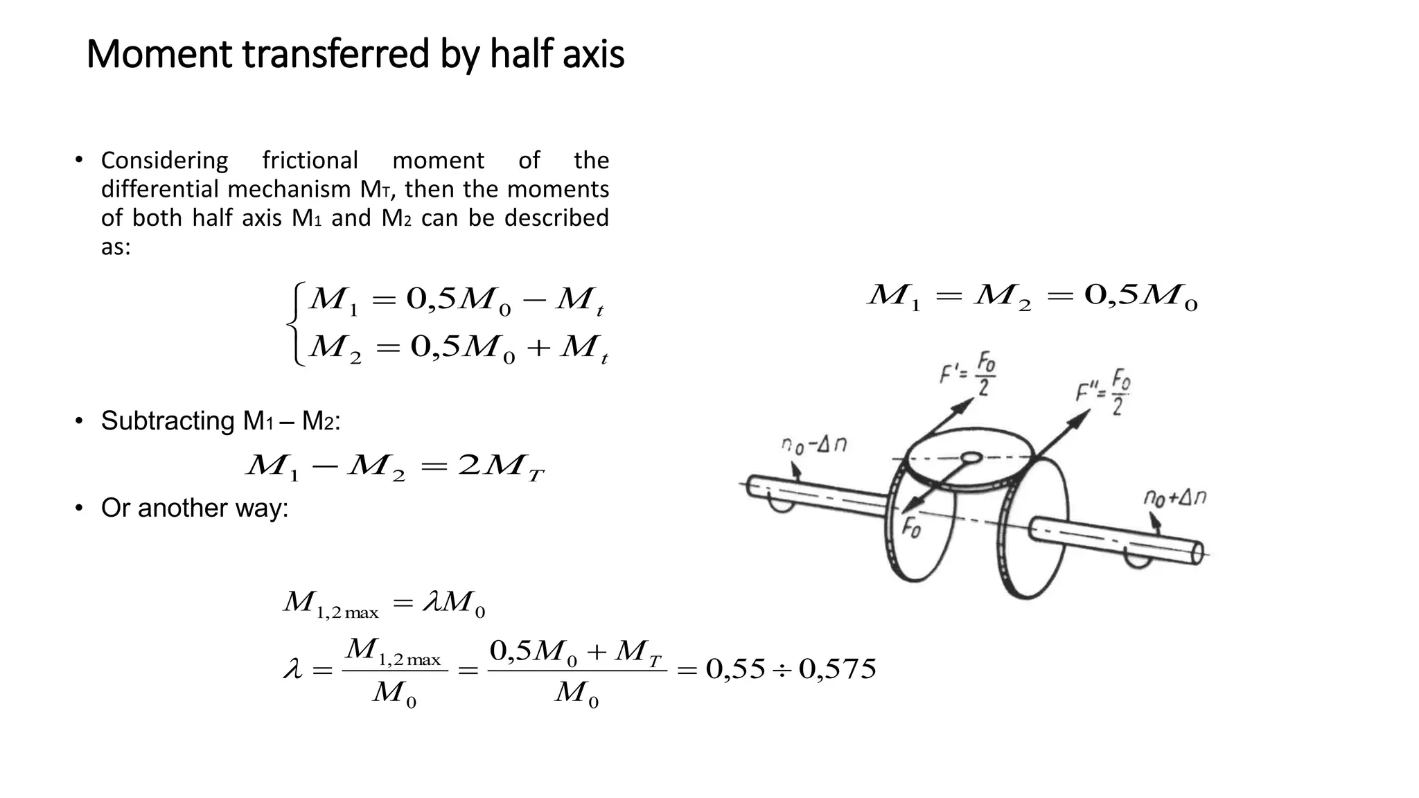
Moment transferred byhalf axis
• Considering frictional moment of the
differential mechanism MT, then the moments
of both half axis M1 and M2 can be described
as:
• Subtracting M1 – M2:
• Or another way:
t
t
M
M
M
M
M
M
0
2
0
1
5
,
0
5
,
0
T
M
M
M 2
2
1
575
,
0
55
,
0
5
,
0
0
0
0
max
2
,
1
0
max
2
,
1
M
M
M
M
M
M
M
T
0
2
1 5
,
0 M
M
M
34.
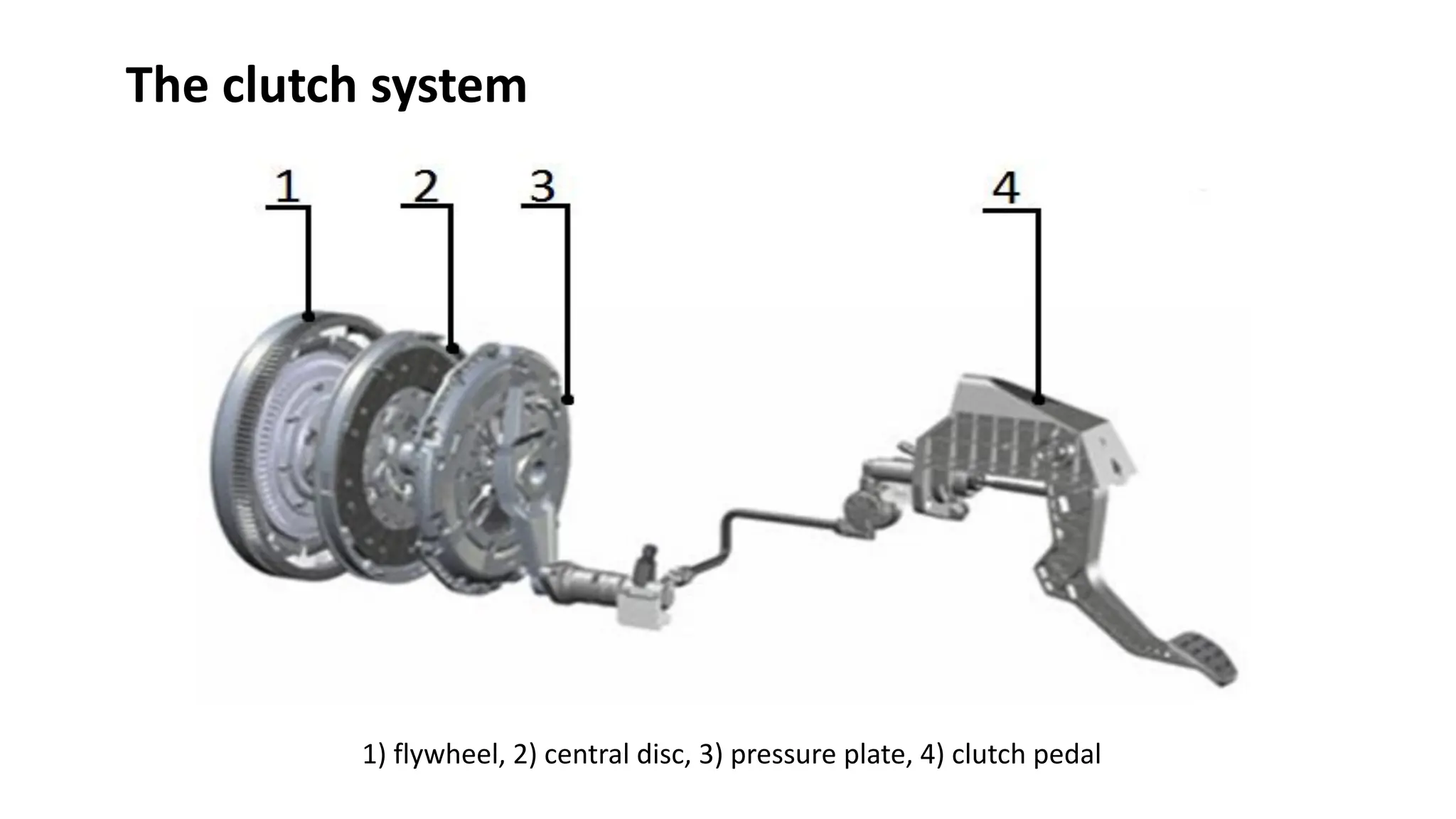
The clutch system
1)flywheel, 2) central disc, 3) pressure plate, 4) clutch pedal
35.
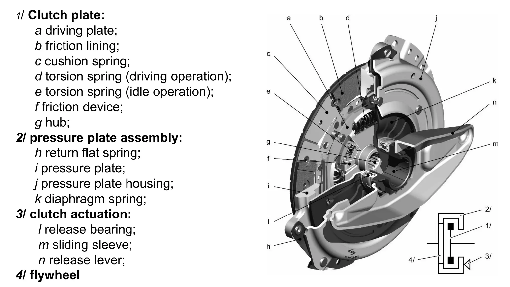
1/ Clutch plate:
adriving plate;
b friction lining;
c cushion spring;
d torsion spring (driving operation);
e torsion spring (idle operation);
f friction device;
g hub;
2/ pressure plate assembly:
h return flat spring;
i pressure plate;
j pressure plate housing;
k diaphragm spring;
3/ clutch actuation:
l release bearing;
m sliding sleeve;
n release lever;
4/ flywheel
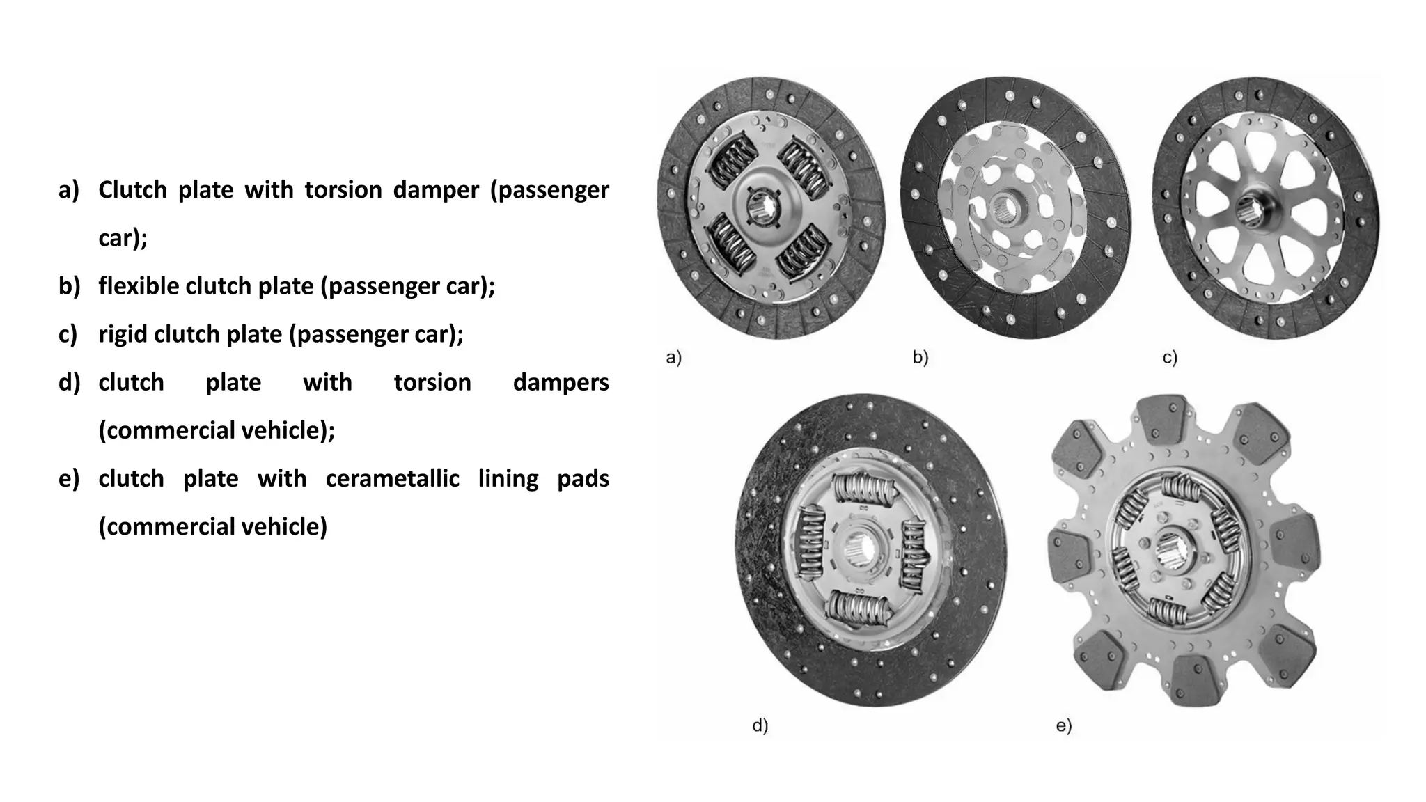
a) Clutch platewith torsion damper (passenger
car);
b) flexible clutch plate (passenger car);
c) rigid clutch plate (passenger car);
d) clutch plate with torsion dampers
(commercial vehicle);
e) clutch plate with cerametallic lining pads
(commercial vehicle)
38.
Literature
CROLLA, D. 2009.Automotive Engineering e-Mega Reference, Elsevier Science.
GARRETT, T. K., NEWTON, K. & STEEDS, W. 2000. Motor Vehicle, Elsevier Science.
HEISLER, H. 2002. Advanced Vehicle Technology, Butterworth-Heinemann.
NUNNEY, M. 2015. Light and Heavy Vehicle Technology, Routledge.
WONG, J. Y. 2001. Theory of Ground Vehicles, Wiley.


![1. SIH2025-IDEA-Presentation-Format[1].pptx](https://cdn.slidesharecdn.com/ss_thumbnails/1-251204091914-b1bb69d5-thumbnail.jpg?width=640&height=640&fit=bounds)


