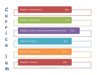
Module 1: ForceSystem 8hrs
Module 2 : Equilibrium 7hrs
Module 3: Center of Gravity and Moment of Inertia 7 hrs.
C
u
r
r
i
c Module 4: Friction 6hrs
Module 5 : Kinematics 6hrs
Module 6 : Kinetics 6hrs
c
u
l
u
m 2
MechanicsGuru_V V Nalawade
3.
Differentiating Factor
Problem BasedTeaching is implemented.
Basic Concepts are taught using Videos, Presentations and Animations.
3
Chalk and Talk is NOT the only Pedagogy.
Analysis for the Live Problems is taught.
MechanicsGuru_V V Nalawade
4.
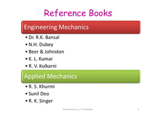
Engineering Mechanics
• Dr.R.K. Bansal
• N.H. Dubey
• Beer & Johnston
• K. L. Kumar
Reference Books
MechanicsGuru_V V Nalawade 4
• K. L. Kumar
• R. V. Kulkarni
Applied Mechanics
• R. S. Khurmi
• Sunil Deo
• R. K. Singer
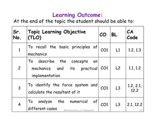
Sr.
No.
Topic Learning Objective
(TLO)
COBL
CA
Code
1
To recall the basic principles of
mechanics
CO1 L1 1.2, 1.3
To describe the concepts on
Learning Outcome:
At the end of the topic the student should be able to:
MechanicsGuru_V V Nalawade 12
2
To describe the concepts on
mechanics and its practical
implementation
CO1 L2 1.1, 1.2
3
To identify the force system and
calculate the resultant of it
CO1 L3
1.2, 2.1,
12.2
4
To analyze the numerical of
different cases
CO1 L3 2.1, 12.2
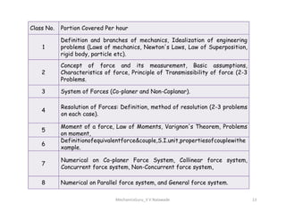
13.
Class No. PortionCovered Per hour
1
Definition and branches of mechanics, Idealization of engineering
problems (Laws of mechanics, Newton's Laws, Law of Superposition,
rigid body, particle etc).
2
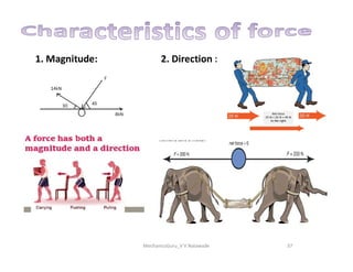
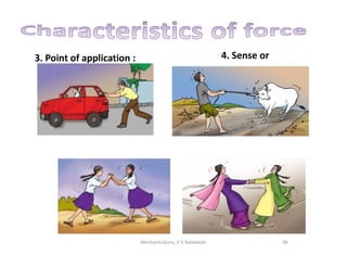
Concept of force and its measurement, Basic assumptions,
Characteristics of force, Principle of Transmissibility of force (2-3
Problems.
3 System of Forces (Co-planer and Non-Coplanar).
4
Resolution of Forces: Definition, method of resolution (2-3 problems
on each case).
MechanicsGuru_V V Nalawade 13
4
Resolution of Forces: Definition, method of resolution (2-3 problems
on each case).
5
Moment of a force, Law of Moments, Varignon's Theorem, Problems
on moment,
6
Definitionofequivalentforce&couple,S.I.unit,propertiesofcouplewithe
xample.
7
Numerical on Co-planer Force System, Collinear force system,
Concurrent force system, Non-Concurrent force system,
8 Numerical on Parallel force system, and General force system.
14.
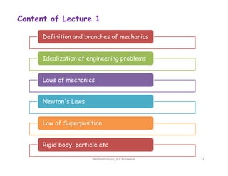
Content of Lecture1
Definition and branches of mechanics
Idealization of engineering problems
Laws of mechanics
MechanicsGuru_V V Nalawade 14
Newton's Laws
Law of Superposition
Rigid body, particle etc
15.
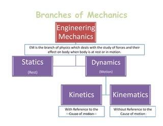
Branches of Mechanics
Engineering
Mechanics
StaticsDynamics
EM is the branch of physics which deals with the study of forces and their
effect on body when body is at rest or in motion.
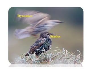
Statics
(Rest)
Dynamics
(Motion)
Kinetics Kinematics
With Reference to the
Cause of motion
Without Reference to the
Cause of motion
MechanicsGuru_V V Nalawade 1
5
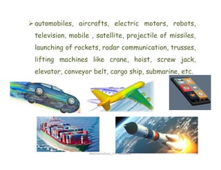
automobiles, aircrafts, electricmotors, robots,
television, mobile , satellite, projectile of missiles,
launching of rockets, radar communication, trusses,
lifting machines like crane, hoist, screw jack,
elevator, conveyor belt, cargo ship, submarine, etc.
MechanicsGuru_V V Nalawade 20
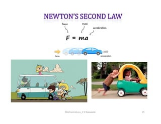
21.
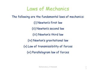
Laws of Mechanics
Thefollowing are the fundamental laws of mechanics:
(i) Newton’s first law
(ii) Newton’s second law
(iii) Newton’s third law
(iv) Newton’s gravitational law
(v) Law of transmissibility of forces
(vi) Parallelogram law of forces
MechanicsGuru_V V Nalawade 2
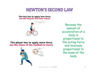
1
Because the
amount of
accelerationof a
body is
proportional to
MechanicsGuru_V V Nalawade 24
proportional to
the acting force
and inversely
proportional to
the mass of the
body
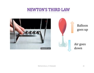
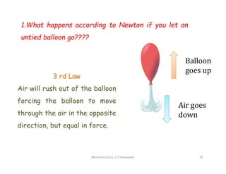
1.What happens accordingto Newton if you let an
untied balloon go????
3 rd Law
Air will rush out of the balloon
MechanicsGuru_V V Nalawade 29
Air will rush out of the balloon
forcing the balloon to move
through the air in the opposite
direction, but equal in force.
30.
2. Describe whathappens if you are riding a skateboard
and hit something (like a curb) with the front wheels???
MechanicsGuru_V V Nalawade 30
1 st Law
Your body will keep moving forward and fly off your
skateboard since the curb only stops the board, not
yourself.
31.
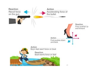
3. Describe whyyou hold your gun next to your
shoulder while deer hunting????
3 rd Law
When you pull the gun’s trigger, it
forces the bullet out of the gun, but
at the same time, the gun is forced
MechanicsGuru_V V Nalawade 31
at the same time, the gun is forced
in the opposite direction of the
bullet (towards you). Your shoulder
is a new force that is introduced in
order to keep your gun from flying
away from you.
32.
4. Why shouldwe wear seatbelts – use one of Newton’s
Laws in your answer?
MechanicsGuru_V V Nalawade 32
We should wear seatbelts so if we are in an accident our body
doesn’t keep moving at the same speed and in the same direction
that the car was going. A new force would be introduced to our
bodies (the seatbelt) in order to keep our bodies in place.
33.
MechanicsGuru_V V Nalawade33
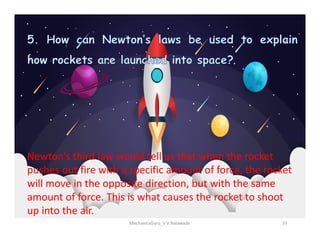
Newton’s third law would tell us that when the rocket
pushes out fire with a specific amount of force, the rocket
will move in the opposite direction, but with the same
amount of force. This is what causes the rocket to shoot
up into the air.
34.
6. Explain howeach of Newton’s laws affects a game of
Tug of War.
•First Law: The rope will stay in the same place until the tugging starts
(a new force is introduced)
•Second Law: We could measure a team’s force that they can pull the
MechanicsGuru_V V Nalawade 34
•Second Law: We could measure a team’s force that they can pull the
rope with based on their body masses and the acceleration that they
are causing the rope to move at.
•Third Law: 1 team pulls the rope towards themselves with a certain
amount of force and the opposing team is also putting force on the rope.
The same amount of force is applied from the ground to the people as
they are putting on the ground.
35.
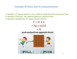
Concept of forceand its measurements
Concept of force and its measurements
35
MechanicsGuru_V V Nalawade
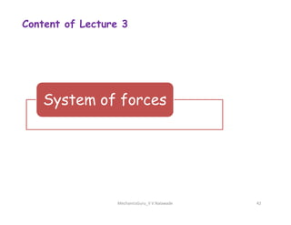
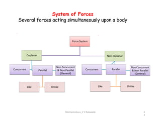
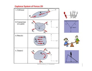
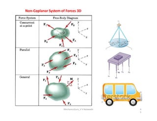
System of Forces
Severalforces acting simultaneously upon a body
Force System
Coplanar Non-coplanar
Concurrent Parallel
Like Unlike
Non Concurrent
& Non Parallel
(General)
Concurrent Parallel
Like Unlike
Non Concurrent
& Non Parallel
(General)
MechanicsGuru_V V Nalawade 4
3
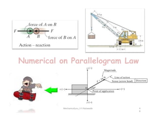
Composition of forces
Forces added to obtain a single force which produces
the same effect as the original system of forces.
This single force is known as Resultant force.
The process of finding the resultant force is called
composition of forces.
MechanicsGuru_V V Nalawade 46
47.
Composition of forces
There are two methods of finding resultant
1. Analytical method
2. Graphical method
Analytical methods are
Parallelogram law &
Method of Resolution
MechanicsGuru_V V Nalawade 47
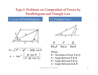
Type I: Problemson Composition of Forces by
Parallelogram and Triangle Law
1.1 Law Of Parallelogram:- 1.2 Triangle Law :-
Sin Sin Sin
R P Q
Where,
R = Resultant of force P & Q
θ = Angle Between P & R
β = Angle Between P & Q
α = Angle Between Q & R
MechanicsGuru_V V Nalawade 4
9
50.
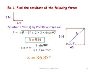
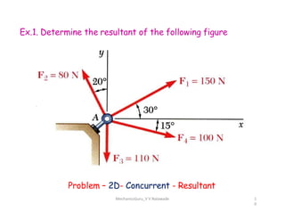
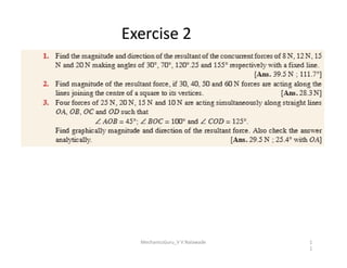
Ex.1. Find theresultant of the following forces
• Solution : Case i) By Parallelogram Law
3 N
4N
3 N
R
R = 5 N
MechanicsGuru_V V Nalawade 50
3 N
4N
α
R = 5 N
51.
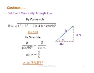
Continue……..
• Solution :Case ii) By Triangle Law
3 N
R
By Cosine rule
R = 5 N
By Sine rule
MechanicsGuru_V V Nalawade 51
3 N
4N
α
By Sine rule
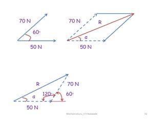
52.
70 N
50 N
60ᵒ
70N
50 N
α
R
MechanicsGuru_V V Nalawade 52
α
70 N
50 N
120ᵒ 60ᵒ
R
Content of Lecture4
Resolution of forces
Definition
MechanicsGuru_V V Nalawade 55
Definition
Problems
56.
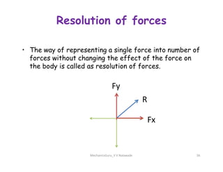
Resolution of forces
•The way of representing a single force into number of
forces without changing the effect of the force on
the body is called as resolution of forces.
Fy
MechanicsGuru_V V Nalawade 56
R
Fx
Fy
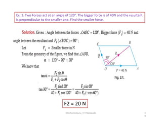
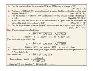
Ex. 1. TwoForces act at an angle of 120°. The bigger force is of 40N and the resultant
is perpendicular to the smaller one. Find the smaller force.
MechanicsGuru_V V Nalawade 5
8
F2 = 20 N
59.
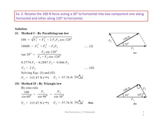
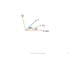
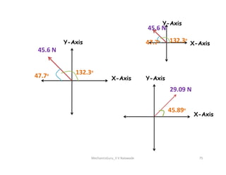
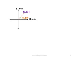
Ex. 2. Resolvethe 100 N force acting a 30° to horizontal into two component one along
horizontal and other along 120° to horizontal.
MechanicsGuru_V V Nalawade 5
9
60.
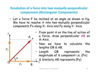
Resolution of aforce into two mutually perpendicular
components (Rectangular Components)
• Let a force F be inclined at an angle as shown in fig.
We have to resolve it into two mutually perpendicular
components Fx along X- Axis and Fy along Y- Axis.
A
• From point A on the line of action of
a force, draw perpendicular AB on
X-Axis.
MechanicsGuru_V V Nalawade 60
A
B
O
X-Axis.
• Now we have to calculate the
lengths OB & AB.
• Length OB represents the
magnitude of X component i.e. (Fx)
• & Similarly AB represents (Fy)
61.
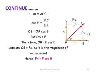
• In ∆AOB,
OB = OA cos θ
But OA = F
A
Fy
Fx
MechanicsGuru_V V Nalawade 61
But OA = F
Therefore, OB = F cos θ
Lets say OB = Fx, as it is the magnitude of
x-component
Hence, Fx = F cos θ
B
O
62.
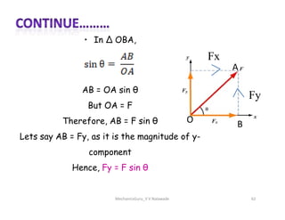
• In ∆OBA,
AB = OA sin θ
But OA = F
A
Fy
Fx
MechanicsGuru_V V Nalawade 62
But OA = F
Therefore, AB = F sin θ
Lets say AB = Fy, as it is the magnitude of y-
component
Hence, Fy = F sin θ
B
O
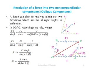
63.
Resolution of aforce into two non perpendicular
components (Oblique Components)
• A force can also be resolved along the two
directions which are not at right angles to
each other.
• In ∆OAC, Applying sine rule, we get
F
F2
F1
α
β
MechanicsGuru_V V Nalawade 63
α
β
(α+β)
F1
F2
F1
F2
O
B C
A
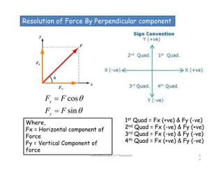
64.
Resolution of ForceBy Perpendicular component
cos
sin
x
y
F F
F F
1st Quad = Fx (+ve) & Fy (-ve)
2nd Quad = Fx (-ve) & Fy (+ve)
3rd Quad = Fx (-ve) & Fy (-ve)
4th Quad = Fx (+ve) & Fy (-ve)
Where,
Fx = Horizontal component of
Force
Fy = Vertical Component of
force
MechanicsGuru_V V Nalawade 6
4
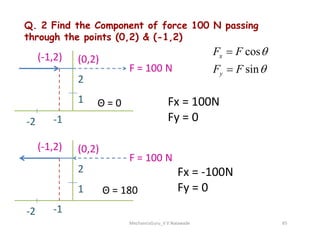
65.
Q. 2 Findthe Component of force 100 N passing
through the points (0,2) & (-1,2)
-1
1
-2
2
(-1,2) (0,2)
F = 100 N
Θ = 0
cos
sin
x
y
F F
F F
Fx = 100N
Fy = 0
MechanicsGuru_V V Nalawade 65
-1
-2
-1
1
-2
2
(-1,2) (0,2)
F = 100 N
Fy = 0
Θ = 180
Fx = -100N
Fy = 0
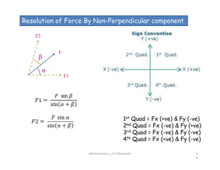
66.
Resolution of ForceBy Non-Perpendicular component
F
F2
F1
α
β
1st Quad = Fx (+ve) & Fy (-ve)
2nd Quad = Fx (-ve) & Fy (+ve)
3rd Quad = Fx (-ve) & Fy (-ve)
4th Quad = Fx (+ve) & Fy (-ve)
MechanicsGuru_V V Nalawade 6
6
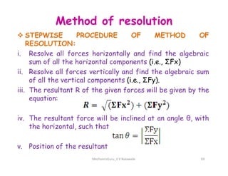
Method of resolution
STEPWISE PROCEDURE OF METHOD OF
RESOLUTION:
i. Resolve all forces horizontally and find the algebraic
sum of all the horizontal components (i.e., ΣFx)
ii. Resolve all forces vertically and find the algebraic sum
of all the vertical components (i.e., ΣFy).
iii. The resultant R of the given forces will be given by the
iii. The resultant R of the given forces will be given by the
equation:
iv. The resultant force will be inclined at an angle θ, with
the horizontal, such that
v. Position of the resultant
MechanicsGuru_V V Nalawade 69
70.
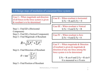
1.4 Design stepsof resolution of concurrent force system :-
Case I :- When magnitude and direction
of all forces in the force system is given
& resultant is to be determined
Step 1:- Find ΣFx (Horizontal
Component)
Step 2:- Find ΣFy (Vertical Component)
Step 3:- Find Magnitude of Resultant
Case II :- When resultant is horizontal
Σ Fx = R and Σ Fy = 0
Case III :- When resultant is Vertical
Σ Fx = 0 and Σ Fy = R
Case IV :- When resultant is Zero
Σ Fx = 0 and Σ Fy = 0
Step 3:- Find Magnitude of Resultant
Step 4:- Find Direction of Resultant
Step 5:- Find Position of Resultant
2 2
x y
R F F
1
tan
y
x
F
F
Σ Fx = 0 and Σ Fy = 0
Case V :- When magnitude & Direction
of resultant is given & magnitude &
direction of any one force among the
force system is to be determined
Σ Fx = R cos θ and Σ Fy = R sin θ
θ is measured w.r.t X-axis
MechanicsGuru_V V Nalawade 7
0
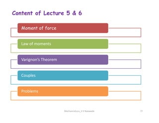
Content of Lecture5 & 6
Moment of force
Law of moments
Varignon’s Theorem
MechanicsGuru_V V Nalawade 77
Varignon’s Theorem
Couples
Problems
78.
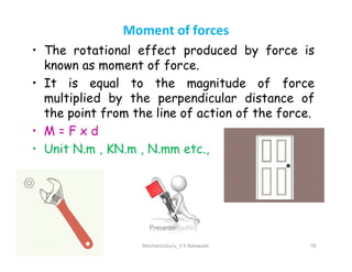
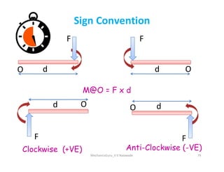
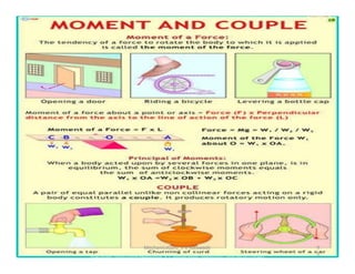
Moment of forces
•The rotational effect produced by force is
known as moment of force.
• It is equal to the magnitude of force
multiplied by the perpendicular distance of
the point from the line of action of the force.
• M = F x d
• M = F x d
• Unit N.m , KN.m , N.mm etc.,
MechanicsGuru_V V Nalawade 78
79.
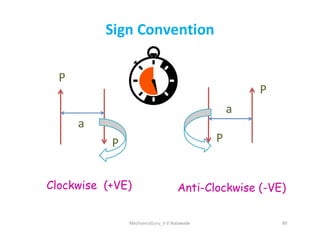
Sign Convention
F
d
O
F
d O
M@O= F x d
MechanicsGuru_V V Nalawade 79
Clockwise (+VE) Anti-Clockwise (-VE)
F
d
O
F
d
O
M@O = F x d
80.
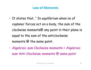
Law of Moments
•It states that, “ In equilibrium when no of
coplanar forces act on a body, the sum of the
clockwise moments@ any point in their plane is
equal to the sum of the anticlockwise
equal to the sum of the anticlockwise
moments @ the same point.
• Algebraic sum Clockwise moments = Algebraic
sum Anti-Clockwise moments @ same point
MechanicsGuru_V V Nalawade 80
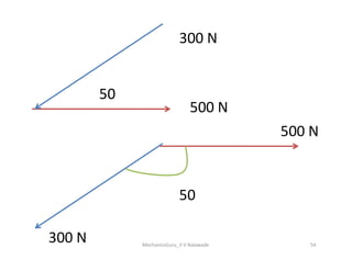
81.
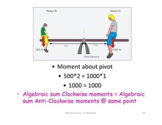
• Moment aboutpivot
• Moment about pivot
• 500*2 = 1000*1
• 1000 = 1000
• Algebraic sum Clockwise moments = Algebraic
sum Anti-Clockwise moments @ same point
MechanicsGuru_V V Nalawade 81
82.
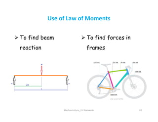
To findbeam
reaction
To find forces in
frames
Use of Law of Moments
MechanicsGuru_V V Nalawade 82
83.
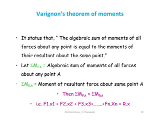
Varignon’s theorem ofmoments
• It status that, “ The algebraic sum of moments of all
forces about any point is equal to the moments of
their resultant about the same point.”
• Let M = Algebraic sum of moments of all forces
• Let ƩMFA = Algebraic sum of moments of all forces
about any point A
• ƩMRA = Moment of resultant force about same point A
• Then ƩMFA = ƩMRA
• i.e. F1.x1 + F2.x2 + F3.x3+……..+Fn.Xn = R.x
MechanicsGuru_V V Nalawade 83
84.
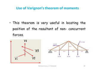
Use of Varignon’stheorem of moments
• This theorem is very useful in locating the
position of the resultant of non- concurrent
forces.
MechanicsGuru_V V Nalawade 84
forces.
85.
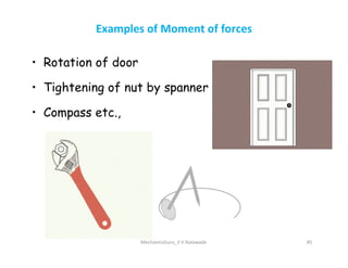
Examples of Momentof forces
• Rotation of door
• Tightening of nut by spanner
• Compass etc.,
MechanicsGuru_V V Nalawade 85
86.
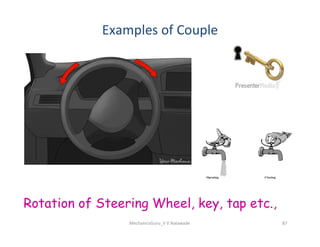
Couple
• Two non-colinear,equal, unlike, parallel forces
forms a couple.
• As the forces are equal & opposite their
resultant is ZERO.
resultant is ZERO.
• Hence couple produces only rotary motion
without producing linear motion.
MechanicsGuru_V V Nalawade 86
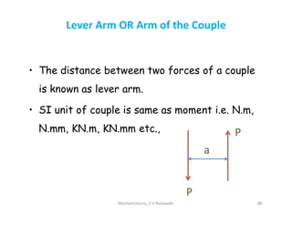
Lever Arm ORArm of the Couple
• The distance between two forces of a couple
is known as lever arm.
• SI unit of couple is same as moment i.e. N.m,
• SI unit of couple is same as moment i.e. N.m,
N.mm, KN.m, KN.mm etc.,
MechanicsGuru_V V Nalawade 88
a
P
P
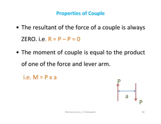
Properties of Couple
•The resultant of the force of a couple is always
ZERO. i.e. R = P – P = 0
• The moment of couple is equal to the product
of one of the force and lever arm.
of one of the force and lever arm.
i.e. M = P x a
MechanicsGuru_V V Nalawade 90
a
P
P
91.
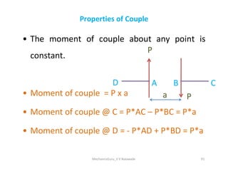
Properties of Couple
•The moment of couple about any point is
constant.
• Moment of couple = P x a
P
D C
B
A
• Moment of couple = P x a
• Moment of couple @ C = P*AC – P*BC = P*a
• Moment of couple @ D = - P*AD + P*BD = P*a
MechanicsGuru_V V Nalawade 91
a P
C
B
A
92.
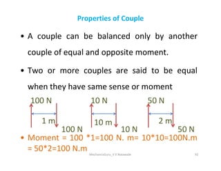
Properties of Couple
•A couple can be balanced only by another
couple of equal and opposite moment.
• Two or more couples are said to be equal
when they have same sense or moment
when they have same sense or moment
• Moment = 100 *1=100 N. m= 10*10=100N.m
= 50*2=100 N.m MechanicsGuru_V V Nalawade 92
2 m
50 N
50 N
10 m
10 N
10 N
1 m
100 N
100 N
93.
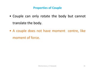
Properties of Couple
•Couple can only rotate the body but cannot
translate the body.
• A couple does not have moment centre, like
moment of force.
moment of force.
MechanicsGuru_V V Nalawade 93
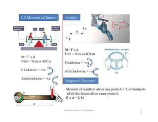
1.5 Moment offorce:-
M= F x d
Unit = N.m or KN.m
Couple:-
M= F x d
Unit = N.m or KN.m
Clockwise = +ve
Unit = N.m or KN.m
Clockwise = +ve
Anticlockwise = -ve
Clockwise = +ve
Anticlockwise = -ve
Varignon’s Theorem:-
Moment of resultant about any point A = Σ of moments
of all the forces about same point A.
R x d = Σ M
MechanicsGuru_V V Nalawade 9
6
97.
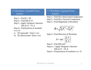
1.6 Resultant ofparallel force
system:-
Step 1:- Find R = ΣF
Step 2:- Find ΣM @ O
Step 3:- Apply Varignon’s theorem
ΣM @ O = R. d
Step 4:- Find position of resultant
w.r.t. O
i) ΣF (upward) = Σmo (+ve)
ii) ΣF (downward) =Σmo (-ve)
1.7 Resultant of general force
system:-
Step 1:- Find ΣFx (Horizontal Component)
Step 2:- Find ΣFy (Vertical Component)
Step 3:- Find Magnitude of Resultant
Step 4:- Find Direction of Resultant
2 2
x y
R F F
ii) ΣF (downward) =Σmo (-ve)
Step 4:- Find Direction of Resultant
Step 5:- Find ΣM @O
Step 6:-:- Apply Varignon’s theorem
ΣM @ O = R. d
Step 4:- Find position of resultant w.r.t. O
1
tan
y
x
F
F
MechanicsGuru_V V Nalawade 9
7
98.
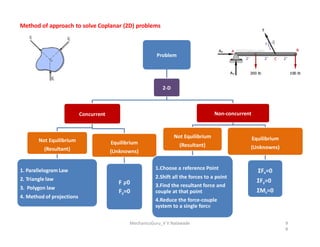
Method of approachto solve Coplanar (2D) problems
Problem
2-D
Concurrent Non-concurrent
Not Equilibrium
(Resultant)
1. Parallelogram Law
2. Triangle law
3. Polygon law
4. Method of projections
Equilibrium
(Unknowns)
F =0
x
Fy=0
Not Equilibrium
(Resultant)
1.Choose a reference Point
2.Shift all the forces to a point
3.Find the resultant force and
couple at that point
4.Reduce the force-couple
system to a single force
Equilibrium
(Unknowns)
ΣFx=0
ΣFy=0
ΣMz=0
MechanicsGuru_V V Nalawade 9
8
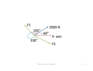
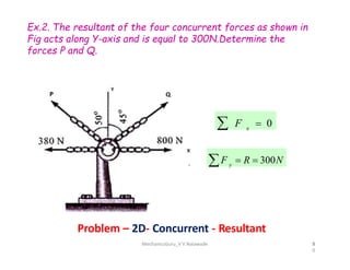
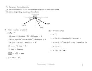
Ex.2. The resultantof the four concurrent forces as shown in
Fig acts along Y-axis and is equal to 300N.Determine the
forces P and Q.
F x
0
Problem – 2D- Concurrent - Resultant
9
F y
R 300N
MechanicsGuru_V V Nalawade 1
0
2
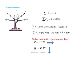
103.
F x
800380QSin45Psin50 0
Problem solution
F x 0
Fy
R 300N
F y
QCos45 PCos50 R 300
Solve quadratic equation and find
P = 511 N
Q = - 40.3N
MechanicsGuru_V V Nalawade 1
0
3
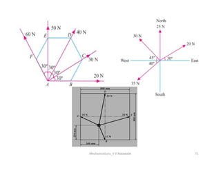
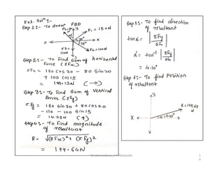
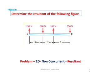
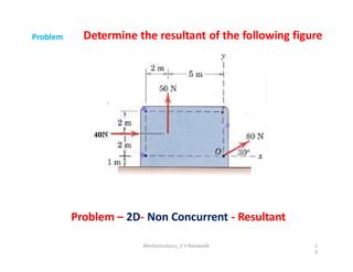
Determine the resultantof the following figure
Problem
Problem – 2D- Non Concurrent - Resultant
MechanicsGuru_V V Nalawade 1
0
5
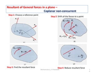
106.
Resultant of Generalforces in a plane –
Coplanar non-concurrent
Step 2: Shift all the forces to a point
Step 1: Choose a reference point
Step 3: Find the resultant force Step 4: Reduce resultant force
MechanicsGuru_V V Nalawade 1
0
6
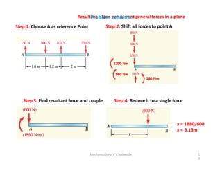
107.
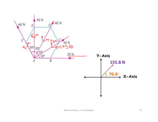
Resultant – Non-concurrentgeneral forces in a plane
Step:1: Choose A as reference Point Step:2: Shift all forces to point A
Problem solution:
Step:4: Reduce it to a single force
Step 3: Find resultant force and couple
x = 1880/600
x = 3.13m
MechanicsGuru_V V Nalawade 1
0
7
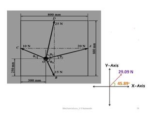
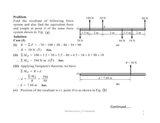
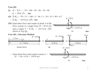
108.
Determine the resultantof the following figure
Problem
Problem – 2D- Non Concurrent - Resultant
MechanicsGuru_V V Nalawade 1
0
8
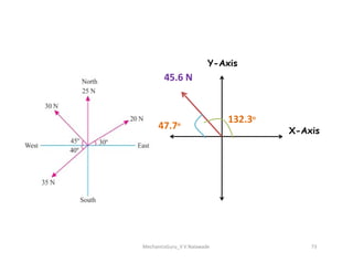
109.
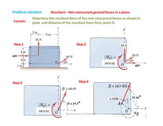
Example:
Resultant – Non-concurrentgeneral forces in a plane
Determine the resultant force of the non-concurrent forces as shown in
plate and distance of the resultant force from point O͛.
Step:2
Step:1
Problem solution
Step:4
Step:3
MechanicsGuru_V V Nalawade 1
0
9