
Recommended
Recommended
More Related Content
What's hot
What's hot (20)
Similar to Enganches 9780429469398-chapter3
Similar to Enganches 9780429469398-chapter3 (20)
Recently uploaded
Recently uploaded (20)
Enganches 9780429469398-chapter3
- 1. This article was downloaded by: 10.3.98.104 On: 23 Mar 2021 Access details: subscription number Publisher: CRC Press Informa Ltd Registered in England and Wales Registered Number: 1072954 Registered office: 5 Howick Place, London SW1P 1WG, UK Handbook of Railway Vehicle Dynamics Simon Iwnicki, Maksym Spiryagin, Colin Cole, Tim McSweeney Design of Unpowered Railway Vehicles Publication details https://www.routledgehandbooks.com/doi/10.1201/9780429469398-3 Anna Orlova, Roman Savushkin, Iurii (Yury) Boronenko, Kirill Kyakk, Ekaterina Rudakova, Artem Gusev, Veronika Fedorova, Nataly Tanicheva Published online on: 02 Dec 2019 How to cite :- Anna Orlova, Roman Savushkin, Iurii (Yury) Boronenko, Kirill Kyakk, Ekaterina Rudakova, Artem Gusev, Veronika Fedorova, Nataly Tanicheva. 02 Dec 2019, Design of Unpowered Railway Vehicles from: Handbook of Railway Vehicle Dynamics CRC Press Accessed on: 23 Mar 2021 https://www.routledgehandbooks.com/doi/10.1201/9780429469398-3 PLEASE SCROLL DOWN FOR DOCUMENT Full terms and conditions of use: https://www.routledgehandbooks.com/legal-notices/terms This Document PDF may be used for research, teaching and private study purposes. Any substantial or systematic reproductions, re-distribution, re-selling, loan or sub-licensing, systematic supply or distribution in any form to anyone is expressly forbidden. The publisher does not give any warranty express or implied or make any representation that the contents will be complete or accurate or up to date. The publisher shall not be liable for an loss, actions, claims, proceedings, demand or costs or damages whatsoever or howsoever caused arising directly or indirectly in connection with or arising out of the use of this material.
- 2. Downloaded By: 10.3.98.104 At: 18:53 23 Mar 2021; For: 9780429469398, chapter3, 10.1201/9780429469398-3 43 3 Design of Unpowered Railway Vehicles Anna Orlova, Roman Savushkin, Iurii (Yury) Boronenko, Kirill Kyakk, Ekaterina Rudakova, Artem Gusev, Veronika Fedorova and Nataly Tanicheva 3.1 GENERAL VEHICLE STRUCTURE, MAIN FUNCTIONS AND TERMINOLOGY Unpowered railway vehicles are mainly operated in trains being drawn by a locomotive or several locomotives distributed along the train. This is the basic technology that is equally used for transporta- tion of freight and passengers, providing high energy efficiency. Further, we refer to freight unpowered vehicles as wagons and passenger vehicles as coaches. Typical examples are shown in Figure 3.1. CONTENTS 3.1 General Vehicle Structure, Main Functions and Terminology.................................................43 3.1.1 Car Bodies...................................................................................................................47 3.1.2 Running Gears, Bogies and Suspensions.....................................................................49 3.1.3 Couplers, Automatic Couplers and Draw Bars............................................................ 51 3.1.4 Pneumatic Brakes........................................................................................................53 3.2 Design of Car Bodies...............................................................................................................54 3.2.1 Passenger Coaches.......................................................................................................54 3.2.2 Freight Wagons............................................................................................................59 3.3 Running Gears and Components.............................................................................................70 3.3.1 Wheelsets.....................................................................................................................71 3.3.2 Axleboxes and Cartridge Type Bearings......................................................................75 3.3.3 Wheels.........................................................................................................................77 3.4 Design of Freight Wagons Bogies............................................................................................79 3.4.1 Three-Piece Bogies......................................................................................................79 3.4.2 Primary Suspended H-Frame Bogies........................................................................... 81 3.4.3 Double-Suspension Bogies..........................................................................................82 3.4.4 Auxiliary Suspensions (Cross-Anchors, Radial Arms, etc.)........................................83 3.5 Design of Unpowered Bogies for Passenger Coaches.............................................................86 3.6 Design of Inter-Car Connections............................................................................................. 91 3.6.1 Screw Couplers............................................................................................................ 91 3.6.2 Automatic Couplers.....................................................................................................92 3.6.3 Draft Gear....................................................................................................................95 3.6.4 Buffers.........................................................................................................................98 3.6.5 Inter-Car Gangways...................................................................................................100 3.7 Principles for the Design of Suspensions............................................................................... 103 3.7.1 Suspension Characteristics in Vertical Direction....................................................... 103 3.7.2 In-Plane Suspension Stiffness....................................................................................106 3.7.3 Suspension Damping.................................................................................................108 3.7.4 Car Body to Bogie Connections................................................................................ 110 References....................................................................................................................................... 112
- 3. Downloaded By: 10.3.98.104 At: 18:53 23 Mar 2021; For: 9780429469398, chapter3, 10.1201/9780429469398-3 44 Handbook of Railway Vehicle Dynamics For any railway vehicle, the axle load (mass transmitted onto the rails by one wheelset) is the major characteristic, along with the maximum design speed. In freight transportation, axle loads between 22.5 t and 37.5 t are used, with design speeds below 160 km/h (the bigger the axle load, the smaller the design speed), whereas the tendency for passenger coaches is increasing the design speed while maintaining the axle load as small as possible. Freight train consists can reach up to 48,000 t in total weight and up to 320 wagons, limited by locomotive capabilities and the landscape of the railway, to achieve maximum efficiency (see heavy- haul freight train example in Figure 3.2). Efficiency of the individual wagon is determined by its mass capacity and volume capacity that indicate the possible maximum mass of the cargo and the absolute maximum volume of the cargo that it can carry. The minimum possible mass of the wagon is its tare mass (when totally empty), and the maximum mass is the fully laden mass (tare plus the capacity) that should not exceed the limitation for the axle load. The length of passenger trains is usually limited by platform size, and speed and comfort are valued more than the mass of the passengers; thus, coaches are characterised by passenger capacity and carry a lot of specific equipment to provide comfort. The locomotive hauls the train, while each unpowered vehicle produces the running resistance due to interaction between the wheel and rail, oscillations and damping in the suspension, friction in bearings, air and gravity resistance, longitudinal oscillations between vehicles, etc. To stop the train, brakes are applied to each vehicle individually. The lifecycle of unpowered vehicles also includes loading and unloading operations (with external or built-in devices), shunting manoeuvres during assembling and disassembling of the train and coupling to and uncoupling from the adjacent vehicles. When in the train, the locomotive accelerates or decelerates the vehicles, and they pass straight or curved sections of the railway track, change tracks when passing through switches and crossings, experience wind and interact with bridges and tunnels. All of these described operational scenarios need to be handled by vehicle design. The main parts of the unpowered railway vehicle are the car body, the bogies and the braking and coupling equipment, as shown in Figure 3.3. Number of axles: In general, the vehicles are classified by the number of axles (wheelsets); exam- ples are shown in Figure 3.4. Some special transport vehicles for super-heavy cargo can have two bogies with up to 8 axles in each of them. There may be more than two sections in articu- lated vehicles or one-axle bogies under the articulation. In addition, bogies in articulated vehi- cles with different numbers of axles can be positioned under the articulation (three-axle) and under the ends of the car body sections (two-axle). Because the axle load is limited, the number of axles is used to distribute the mass of the vehicle over the length of the railway track. (a) (b) FIGURE 3.1 Examples of unpowered rail vehicles: (a) freight wagon and (b) passenger coach. ([b] From Transmashholding, Moscow, Russia. With permission.)
- 4. Downloaded By: 10.3.98.104 At: 18:53 23 Mar 2021; For: 9780429469398, chapter3, 10.1201/9780429469398-3 45 Design of Unpowered Railway Vehicles The following characteristics are used to describe the geometry of railway vehicles: Vehicle wheel base: Wheel base of the vehicle is the longitudinal dimension between the cen- tres of outer bogies or between the centres of outer suspensions of the vehicle. For articu- lated vehicles, as shown in Figure 3.5, besides the wheel base of the whole vehicle, the wheel base of each section can be used, designating the longitudinal distance between the centres of neighbouring bogies. FIGURE 3.2 Heavy-haul freight train. FIGURE 3.3 Main parts of unpowered railway vehicle. (1) car body, (2) bogies, (3) braking equipment and (4) coupling equipment.
- 5. Downloaded By: 10.3.98.104 At: 18:53 23 Mar 2021; For: 9780429469398, chapter3, 10.1201/9780429469398-3 46 Handbook of Railway Vehicle Dynamics Length between coupler axes: The length of the vehicle in the train or how much space it takes up in the train is measured between the axes of the coupling devices. This parameter is also important for spacing the loading and unloading devices at the terminal facilities and for distributing the mass of the vehicles in the train over the length of the track. The bearing capacity of bridges that are longer than one vehicle is determined by the permissible load per unit length of the vehicle, that is, fully laden weight of the vehicle divided by its length between coupler axes. To provide safe curving, the length of four-axle vehicles between coupler axes does not exceed 25 m. FIGURE 3.4 Types of rail vehicles by the number of axles: (a) 2-axle vehicle, (b) 4-axle vehicle with two 2-axle bogies, (c) 6-axle vehicle with two 3-axle bogies, (d) 6-axle articulated vehicle with three 2-axle bogies and (e) 8-axle vehicle with two 4-axle bogies. FIGURE 3.5 Dimensions of articulated vehicle: 2L – vehicle wheelbase, Ls – section wheel base, 2Lc – length between coupler axes, 2Lb – length between end beams, 2Lt – length of the car body and C – length of the cantilever part.
- 6. Downloaded By: 10.3.98.104 At: 18:53 23 Mar 2021; For: 9780429469398, chapter3, 10.1201/9780429469398-3 47 Design of Unpowered Railway Vehicles Length of the cantilever part: The difference between the length between coupler axes and vehicle wheel base is double the length of the cantilever part. This parameter becomes important when the vehicles in the train are passing curved sections of the track, because it determines the lateral displacement of the coupling devices. Car body length: Car body length is its maximum dimension along the track. In most vehicles, car body length equals the length between end beams, but some designs have a protruding top part that increases the loading volume. Coupler height (above the rail top level): This parameter determines the safety of coupling and prevents uncoupling when the train is moving over summit parts of sloped track. In production, the coupler height is measured in empty vehicles, and it depends on the tolerance for bogie height and tolerances of car body centre sill, as well as the tare weight of the empty car body. In operation, the coupler height is even more variable, as it is depen- dent on wheel diameter that changes due to turning, suspension deflection that increases when the vehicle is loaded, wear of bogie horizontal surfaces and wear of coupling device surfaces. The railway administrations set safety limits for coupler height in empty and laden vehicle conditions [1,2]. Clearance diagram: The vehicle dimensions in cross-section laterally to the track are limited by the so-called clearance diagram. Two tracks can be laid next to each other, various platforms and other buildings stand near the track and tracks can go over bridges and into tunnels, and on electrified railways, there is the contact wire running over the track. To limit the vertical (top and bottom) and lateral dimensions of the vehicle and to provide safe clearance between the vehicle and stationary structures on straight track and in curves, the clearance diagram was introduced. Conformity of vehicles to clearance diagrams is a basic safety requirement of all railway administrations [3–5]. 3.1.1 Car Bodies During almost 200 years, the evolution of freight wagons and coaches created a huge number of various car body designs for many purposes. Typical examples are shown in Figure 3.6. There are specific freight wagons to carry bulk named gondola wagons (either drop bottom or solid bottom), to carry grain or mineral fertilisers with the capability of discharge though bottom hatches named hopper wagons, to carry liquids named tank wagons, to carry containers named flat wagons, as well as more specific designs. FIGURE 3.6 Various types of freight wagon car bodies: (a) drop-bottom gondola, (b) timber flat wagon, (c) tank wagon and (d) hopper wagon.
- 7. Downloaded By: 10.3.98.104 At: 18:53 23 Mar 2021; For: 9780429469398, chapter3, 10.1201/9780429469398-3 48 Handbook of Railway Vehicle Dynamics Passenger coaches differ by either providing travel for sitting or sleeping passengers; there also exist restaurant coaches, laboratory coaches with measurement equipment to monitor railway condi- tion and many other specific types. To increase the passenger capacity of the coach, double decks, as shown in Figure 3.7, can be introduced if the clearance diagram permits. No matter the variety of car body types, in rail vehicle dynamics, they can be presented either as rigid bodies or as rigid bodies with certain elastic properties. If eigenfrequencies of the car body structure in the empty or laden condition are within the range of the suspension oscillation frequen- cies (0–20 Hz), then elastic properties of the car body will influence the performance of the vehicle on track and should be taken into account when simulating vehicle dynamics. A typical example of elastic behaviour of a freight wagon is bending oscillations of an 80-foot long container flat [6], as shown in Figure 3.8. The situation of low car body frequencies appears more often for passenger coaches because reduction of tare mass makes the body more flexible. In passenger vehicles, the eigenmodes of the car body not only influence the ride performance but also affect passenger comfort, and standards therefore limit the value of the first eigenmode frequency to be higher than 8 or 10 Hz [7]. Research is being done by Japanese scientists [8] that is aimed to use piezoelectric technology to provide addi- tional damping for eigenmodes of super-light car bodies. Other research tends to implement control in suspensions to dampen the car body’s eigenmodes as well as its rigid-body oscillations [9]. The car body is the part that establishes the existence of the railway vehicle in technical terms; it unites all systems, houses cargo or passengers to provide safety of transportation in all operational modes and bears the registration number of the vehicle as the only non-replaceable part. The car body rests on bogies (or suspensions) and interacts with them through car body to bogie connec- tions. Adjacent car bodies are joined in a train via inter-car connections: coupling devices, passages and additional inter-car dampers to improve ride quality. The car body is used to position braking equipment. Interaction of wagons and cargo is a separate and very important part of vehicle system dynam- ics. Semi-trailers have their own road suspension and oscillate while the train is in motion [10]. Liquid cargo sloshes inside a tank, changing its behaviour on straight track and in curves [11,12]. Wood or even bulk cargo can displace under the action of longitudinal impacts. Interaction of vehicle and passengers is also important, producing much research on the percep- tion of oscillations by people [13] and modelling of human bodies in different postures [14]. FIGURE 3.7 Double deck passenger coach. (From Transmashholding, Moscow, Russia. With permission.)
- 8. Downloaded By: 10.3.98.104 At: 18:53 23 Mar 2021; For: 9780429469398, chapter3, 10.1201/9780429469398-3 49 Design of Unpowered Railway Vehicles 3.1.2 Running Gears, Bogies and Suspensions The principal difference between a railway vehicle and other types of wheeled transport is the guidance provided by the railway track. The surface of the rails not only supports the wheels but also guides them in the lateral direction. The rails and the switches change the rolling direction of wheels and thus determine the direction of travel of the railway vehicle. Irregularities on the rails produce oscillations of the vehicles. The running gear is the system that provides safe motion of the vehicle along the railway track. The running gear includes such components as wheelsets with bearings, the elastic suspension, the brakes and the device to transmit traction and braking forces to the car body. Its main functions are as follows: • Transmission and equalisation of the vertical load from the wheels of the vehicle to the rails • Guidance of the vehicle along the track • Control of the dynamic forces due to motion over track irregularities, in curves, switches and after impacts between the vehicles • Efficient damping of oscillations • Application of braking forces Depending on the running gear, the vehicles may be described as bogied or bogie-less. In vehicles without bogies, the suspension, brakes and traction equipment are mounted on the car body. The traction and braking forces are transmitted through traction rods or axlebox guides (sometimes known as ‘hornblocks’) straight onto the wheelset. The typical example is the con- ventional two-axle wagon (see Figure 3.9), which generates larger forces in tight curves than the equivalent bogie vehicle; therefore, the length of the former is limited. Running gear mounted on a separate frame that can turn relative to the vehicle body is known as a bogie (or truck). The number of wheelsets that they unite classifies the bogies. The most common type is the two-axle bogie, but three- and four-axle bogies are also encountered. Typical examples are shown in Figure 3.10. Early bogies simply allowed the running gear to turn in the horizontal plane relative to the car body, thus making it possible for the wheelsets to have smaller angles of attack in curves. In modern bogies, the bogie frame transmits all the longitudinal, lateral and vertical forces between the car body and the wheelsets. The frame also carries braking and traction equipment, suspension and (a) (b) FIGURE 3.8 Typical examples of elastic behaviour of freight flat wagon: (a) bending mode with 11.5 Hz eigenfrequency and (b) torsion mode with 11.8 Hz eigenfrequency.
- 9. Downloaded By: 10.3.98.104 At: 18:53 23 Mar 2021; For: 9780429469398, chapter3, 10.1201/9780429469398-3 50 Handbook of Railway Vehicle Dynamics FIGURE 3.9 Bogie-less two-axle wagon. (From Corporate Media People, Moscow, Russia. With permission.) (a) (b) (c) FIGURE 3.10 Typical examples of: (a) bogied wagon, (b) two-axle bogie and (c) three-axle bogie.
- 10. Downloaded By: 10.3.98.104 At: 18:53 23 Mar 2021; For: 9780429469398, chapter3, 10.1201/9780429469398-3 51 Design of Unpowered Railway Vehicles dampers. It may house tilting devices, lubrication devices for wheel-rail contact and mechanisms to provide radial positioning of wheelsets in curves. Bogied vehicles are normally heavier than two- axle vehicles. However, the design of railway vehicles with bogies is often simpler than for two-axle vehicles, and this may provide reliability and maintenance benefits. The following characteristics are used to describe the bogies: Track gauge: To correspond to the track gauge of the railway and to provide appropriate wheelsets. Axle load and design speed: These are used to check the compatibility of the bogie with the designed vehicle. (Bogie) wheel base: Wheel base of the bogie is the longitudinal dimension between the cen- tres of its outer wheelsets. This parameter is important for distributing the mass of the vehicles over the length of the track. The bearing capacity of bridges that are shorter than one vehicle is determined by the permissible load per unit length of the vehicle, that is, fully laden weight of the vehicle per one bogie divided by bogie wheel base. Car body support height over the top of rails: The height is measured between the top of the rail and the centre bowl surface or the surface of the other elements that support the car body. In production, measurements are usually taken in free bogie condition and can vary depending on wheel diameter tolerance, suspension element tolerances, production toler- ances of cast or fabricated frames and beams. After the car body is positioned over the bogie, the height reduces, depending on the suspension deflection under the tare weight. The parameter is important for safety to provide tare vehicle coupler height. Clearance diagram: The bogie dimensions in cross-section laterally to the track are limited by the so-called clearance diagram. Besides requirements that limit the lateral dimensions of the bogies in the same way as the dimensions of the car bodies, there exist special limits on the vertical distance between the bottom of the bogie and on-track devices. Suspension deflection under empty/laden vehicle conditions: The values of deflection are used to check whether the bogie is appropriate under the chosen vehicle and will provide safety limits of coupler height. 3.1.3 Couplers, Automatic Couplers and Draw Bars Various devices are positioned in the end sections of the car body to provide connection between adjacent vehicles in a train, transmitting longitudinal tension and compression forces, providing damping of longitudinal train oscillations and allowing necessary angles of rotation and vertical and lateral displacements for safe passing of curves and humps. These same devices are working when the train is formed out of separate wagons or coaches, facilitating coupling and uncoupling operations when impacts between vehicles need to be handled by the coupling devices. In general, the coupling devices can work either manually (see screw coupling design in Figure 3.11) or in automatic mode (see automatic coupler design in Figure 3.12). Manual operation is done by the railway staff who lift the screw coupling and connect it to the adjacent vehicle; thus, the screw coupling [15] weight and tension capacity are limited by human capability. Automatic operation is done either by running the vehicle off the sorting yard hump or by moving it by loco- motive, with an impact onto the adjacent vehicle. The speed range during sorting is usually below 5 km/h. The special shape of the automatic coupler surfaces [16,17] guides the automatic couplers into their locking position. However, to unlock the automatic couplers, manual force is needed to raise the lock. The introduction of automatic couplers allowed the transmission of much bigger tension as well as compression forces in the train, thus providing for increases in train length and weight. It also speeds up the train sorting operations and provides much higher safety for railway staff who do not need to go between the vehicles during train forming operations.
- 11. Downloaded By: 10.3.98.104 At: 18:53 23 Mar 2021; For: 9780429469398, chapter3, 10.1201/9780429469398-3 52 Handbook of Railway Vehicle Dynamics Two adjacent automatic couplers have longitudinal slack (clearance) between the coupling sur- faces that results from tolerances and wear in operation. In train starting mode, the slack allows the locomotive to start moving the vehicles one by one and not the whole train consist at once, thus providing energy efficiency. However, in train transition modes from traction to braking, the slack results in impacts between adjacent vehicles that increase accelerations and make ride comfort poor. Therefore, slackless couplers are often used in coaches instead of automatic couplers. In freight wagons, two or more of them can be connected by slackless draw bars if loading and unloading operations allow it. Vehicles in one train can have different coupler heights due to wear of wheels or deflection of the suspension that can vary due to oscillations in motion. Therefore, the couplers need to have a possibil- ity of relative vertical displacement and are characterised by a safety limit on coupler height difference. To provide damping of the oscillations in a train, the screw coupling is usually used together with buffers (Figure 3.11) that work only in compression and provide elastic resistance and friction damping [18]. FIGURE 3.11 Wagon with (1) screw coupling and (2) a pair of buffers. FIGURE 3.12 Wagon with SA-3 automatic coupler and draft gear. (1) coupler body; (2) lock; (3) yoke; and (4) draft gear.
- 12. Downloaded By: 10.3.98.104 At: 18:53 23 Mar 2021; For: 9780429469398, chapter3, 10.1201/9780429469398-3 53 Design of Unpowered Railway Vehicles In automatic couplers, the special damping device named the draft gear is installed inside the centre sill (Figure 3.12). The draft gear is the damper with initial pre-compression that works in compression when tension or compression forces are applied to the coupler. The yoke transforms both tension and compression forces into compression of the draft gear. The main characteristic of the draft gear is its energy-absorption capacity under the impact conditions. Friction draft gears have the lowest energy capacity; higher capacity is provided by friction-elastomer draft gears, elas- tomer or even hydraulic ones. 3.1.4 Pneumatic Brakes The major brake type for unpowered railway vehicles around the world is the automatic pneumatic brake, where the brake control signals are transmitted from the locomotive onto each vehicle in a train by changing the pressure in the pneumatic train line brake pipe. Each vehicle houses braking equipment such as the brake pipe, air distributor, spare tank, brake cylinder, brake rigging, brake shoes and an empty-load device, as shown in Figure 3.13. When the pressure in the train line brake pipe increases in charging mode or brake release mode, then the air distributor charges the spare tank and connects the brake cylinder with atmosphere. When the brake pipe pressure decreases in brake application mode, then the air distributor connects the spare tank with the brake cylinder. The braking force from the shaft of the brake cylinder is transmitted through the brake rigging onto the brake shoes that press against the wheels in tread brakes. In disc brakes, the force is transmitted by callipers onto the brake pads that press against the brake discs. Friction between the brake shoes and wheel treads, or between the brake pads and discs, decelerates the vehicle. FIGURE 3.13 General composition of braking equipment on a freight wagon. (1) train line brake pipe; (2) air distributor; (3) spare tank; (4) brake cylinder; (5) brake rigging; (6) brake shoes; (7) empty-load device; and (8) end cock.
- 13. Downloaded By: 10.3.98.104 At: 18:53 23 Mar 2021; For: 9780429469398, chapter3, 10.1201/9780429469398-3 54 Handbook of Railway Vehicle Dynamics The term ‘automatic’ is used for this type of brake equipment because it automatically applies the brake when the vehicles in the train or the train line brake pipe disconnect in the case of an accident. Pneumatic brake can be applied in normal operational mode to slowly decelerate the train or in emergency braking mode that corresponds to the same situation of an open mainline in the case of an accident. The following characteristics are used to describe the vehicle brake system: Shoe force: The physical value of the force applied from the brake shoe to the wheel tread. Friction coefficient: The friction coefficient between the brake shoe or pad and the wheel tread or brake disc surface. The coefficient is non-linearly dependent on the vehicle speed and the materials of the friction surfaces. Vehicle stop distance: The distance that the single vehicle will travel from its initial speed to a full stop after the emergency brake is applied or the train line brake pipe disconnects. The stop distance of a single vehicle is measured in tests on straight horizontal track. Train stop distance: The distance that the train consisting of identical vehicles will travel from its initial speed to a full stop after the emergency brake is applied. Train stop distance is usually bigger than the vehicle stop distance because the pressure decrease wave needs to travel through the train to reach every vehicle. Train stop distance is highly dependent on track gradient. Skidding: Skidding between the braked wheel and the rail occurs when the brake force is bigger than the wheel-rail traction force. It increases the stop distance and produces wheel and rail defects. Wheel-rail traction force depends on the actual axle load of the vehicle. This becomes important for wagons because the weight of the empty one can be five times lower than that of the laden one. To avoid skidding, the pressure in the brake cylinder needs to depend on the actual weight of the car body. Special empty-load devices control the brake cylinder pressure, depending on suspension deflection. The anti-skidding devices are sometimes introduced in passenger coaches, especially with disc brakes. Braking is a source of longitudinal compression forces originating in couplers of vehicles in a train. Non-synchronous braking of vehicles makes the back part of the train run onto the front part, creating the compression forces. This problem is specifically important in long freight trains and is often dealt with by driving them using several locomotives distributed along the train [19]. When assessing derailment safety, it is necessary to simulate the situation when the heavy train passes through the curve and the emergency brake is applied that produces large quasi-static com- pression forces on the couplers that press the light (empty) vehicle out of the curve [20]. On straight track, the large compression forces can lead to various train buckling modes [21,22], and again, the assessment of derailment stability is necessary. 3.2 DESIGN OF CAR BODIES 3.2.1 Passenger Coaches To provide the requirements of stiffness, deformations and structural strength, the car bodies for passenger coaches bear the external loads from all parts, such as the frame with the floor, two side walls and two end walls and the roof (see Figure 3.14). Inside the car body, there are structures that do not bear main loads, such as internal walls that split the interior into compartments, toilets, staff rooms, etc. Splitting the bearing structure of the car body by functions, it is possible to distinguish the top compartment (under the roof), the middle compartment (being actually the space utilised by
- 14. Downloaded By: 10.3.98.104 At: 18:53 23 Mar 2021; For: 9780429469398, chapter3, 10.1201/9780429469398-3 55 Design of Unpowered Railway Vehicles passengers) and the bottom part (where various items of equipment are installed). The top compart- ment houses ventilation and conditioning systems, water tanks and tubes. In the bottom part, the frame supports the power generator, batteries, refrigeration units, tanks for used water and other devices providing comfort. In some coaches, the bottom part is open; in others, it is covered with decks or can even be protected by a load bearing structure to increase the car body stiffness. Most common material for car bodies is low-alloyed steel. In the desire to make the car body lighter, to increase its reliability and durability as well as improve its external look, designers are constantly searching for new materials, designs and technology solutions. In high-speed trains, the aluminium alloys and stainless steel initially found application. Later, various non-metal materials such as plastics, fibreglass and carbon fiber reinforced polymer composites, multi-layer panels and honeycomb panels were implemented. Aluminium alloys have better material strength and lower density than steel, do not corrode and are easy to cut and shape. Aluminium car bodies can dissipate much energy to deformation in conditions of an accident, thus providing better safety. At the same time, aluminium alloys have an elasticity modulus that is three times lower than that of steel, which makes the structures prone to stability loss under compressive loads and decreases their stiffness and modal oscillation fre- quencies. To override these problems, the aluminium-bearing structures need bigger sizes of cross- sections than steel ones. The bearing structures of coaches can be classified into three types: Reinforced sheets: The main bearing structure are the metal (steel, aluminium or stainless steel) sheets that are reinforced by beams with various shapes of cross-sections. Sometimes, to prevent the sheets from buckling, the corrugated design is used, or the sheets are rein- forced with stringers. Beams and sheets are assembled with welding or rivets. Use of weld- ing produces visible deformations of sheets that spoil the visual appearance of the car body. FIGURE 3.14 Main parts of a passenger coach car body.
- 15. Downloaded By: 10.3.98.104 At: 18:53 23 Mar 2021; For: 9780429469398, chapter3, 10.1201/9780429469398-3 56 Handbook of Railway Vehicle Dynamics Carcass systems: The main bearing structures are massive rods with open or closed cross- sections. External sheets just increase the general stiffness of the system. External sheets can be light alloys or plastics that provide a better visual appearance and do not need to bear significant loads. Panel systems: Loads are transmitted onto the bearing panels that consist of external and internal walls joined together. Such panels are more often produced out of extruded alu- minium profiles joined with arc welding or stir welding to form the floor, walls and roof. Extruded panels after stir welding do not have any surface defects and provide high struc- tural strength and good visual appearance. In another case, honeycomb panels (sandwich systems) consisting of external and internal shells joined together with porous polyure- thane or foam-aluminium or composite filling are used. Advantages of panels are their ability to damp vibrations and to provide sound and thermal insulation. Let us consider the car body design with beam-reinforced metal sheets. The frame (Figure 3.15) consists of the centre sill 1, transverse beam 2, end beam 3, side beams 4, lateral beams 5, lateral floor beams 6 and metal floor sheet 7 that has openings for various service pipes and ducts to pass through. FIGURE 3.15 Passenger coach frame. (1) centre sill; (2) transverse beam; (3) end beam; (4) side beams; (5) lateral beams; (6) lateral floor beams; and (7) metal floor sheet.
- 16. Downloaded By: 10.3.98.104 At: 18:53 23 Mar 2021; For: 9780429469398, chapter3, 10.1201/9780429469398-3 57 Design of Unpowered Railway Vehicles The roof (Figure 3.16) has uniformly spaced arches 1 that are covered with corrugated sheets 2 having a 2 mm thickness and having bent side sheets 3. The roof has air supply openings 5, hatch 4 and covers 6 and 7 that provide access to various equipment in the top part of the coach. The side wall (Figure 3.17) is the welded whole-metal structure constructed out of corru- gated and plane sheets with thickness of 2–2.5 mm supported by carcass bracing on the inside. The side wall consists of the top belt 1 and bottom belt 2, which are interconnected between each other with fabricated beams 3, and windows 4 and 5 comprising the middle belt. The wall is reinforced with profiled elements of the top beams 6, racks for the doors 7, vertical racks 8 and longitudinal beams 9. FIGURE 3.16 Passenger coach roof. (1) Arch; (2) corrugated sheet; (3) side sheet; (4) hatch; (5) air supply; (6) and (7) covers. FIGURE 3.17 Passenger coach side wall. (1) Top belt; (2) bottom belt; (3) middle belt with fabricated beams; (4) compartment window; (5) toilet window; (6) top beam; (7) rack for the door; (8) vertical rack; and (9) lon- gitudinal beams.
- 17. Downloaded By: 10.3.98.104 At: 18:53 23 Mar 2021; For: 9780429469398, chapter3, 10.1201/9780429469398-3 58 Handbook of Railway Vehicle Dynamics The end wall (Figure 3.18) consists of the corner racks 1, roof arc 2 and two anti-impact racks 3, which are welded to the bottom of the frame end beam (see Figure 3.15) and to the lateral beam 4, that altogether provide safety for passengers in the case of accidents. The bearing structures are covered with metal sheets 5, additionally reinforced by ribs 6. Years of operation have shown that relatively simple reinforced sheet structures of car bodies have one significant disadvantage. Their lower bending mode frequency is often less than 8 Hz, and they can come into resonance with suspension oscillations worsening the ride performance and passenger comfort. In carcass-type designs, the coach frame consists of the centre sill, with side and transverse beams having box cross-sections. Corrugated sheets used in the bottom and floor further increase the stiffness of the whole system. The side walls of the car body are based on a grid of vertical and horizontal beams. Parts of the beams are narrow and higher and others are wider and thinner. This allows joining them by stamping thinner elements into the higher ones. Altogether, this pro- vides a stiff and stable system. The shell is attached to the carcass with spot welding, thus providing a better visual appearance, as spot welding gives less buckling and deformation. To increase the roof stiffness, the arches are installed. Longitudinal stiffness of the roof can either be provided with stringers or corrugated sheets of the shell. General stiffness of a carcass-type car body is higher than that for sheet structures; however, the variability of elements makes the production more labour intensive, increasing the cost of the design. Spot welding needs special attention when applying the coatings. The typical example of carcass design is the TGV train car body shown in Figure 3.19. The frame is not symmetrical because the example shows the end coach that couples to the locomotive when forming the train. The left part of the car body rests on the bogie through a transverse beam (see 7 on side A), and the right part (side B) rests on an articulated bogie that supports two adjacent car bodies simultaneously. Pay attention to the massive carcass of the side walls. The bottom part of the car body consists of frames joined with longitudinal elements, while the floor and the roof are corrugated sheets. Testing showed that the first bending frequency is higher than 10 Hz. FIGURE 3.18 End wall of the passenger coach. (1) corner racks; (2) roof arc; (3) anti-impact rack; (4) lateral beam; (5) metal sheet; and (6) reinforcement ribs.
- 18. Downloaded By: 10.3.98.104 At: 18:53 23 Mar 2021; For: 9780429469398, chapter3, 10.1201/9780429469398-3 59 Design of Unpowered Railway Vehicles The panel type design allows to have an even lighter, stiffer and more reliable car body structure. The main idea is to use large extruded aluminium profiles for the external shell (see Figure 3.20). Extruded profiles are joined with automatic arc welding, followed by grinding the welds or by stir welding. The resulting panels have large bending stiffness and local structural strength to withstand point loads. This property is used to attach internal and external equipment. The main advantages are low production cost and a smaller number of components. However, the extruded panels are often too strong and do not provide sufficient sound and ther- mal insulation; in such cases, they are replaced with sandwich or honeycomb panels. A typical example of panel design is the Talgo train coach (Figure 3.20a). It uses extruded aluminium profiles for the floor and walls. The bottom part of the floor has guides that are used to support the equipment under it. Side walls have windows and doors reinforced with vertical beams. By the end of the 1990s, much research work was aimed to choose the best design of car bodies for coaches and locomotives. The lightest car bodies with maximum stiffness and structural strength were found to be provided by soldered honeycomb panels that are, at the same time, the most expen- sive in production. Riveted airplane-type designs were tested as well and did not find practical application. Currently, the double-skin design constructed out of volumetric extruded aluminium profiles seems to have good prospects; however, it is mainly used in high-speed rollingstock. 3.2.2 Freight Wagons The design of a freight wagon body is determined by its purpose [23–26]. Railway freight wagons are used to transport liquid, loose or bulky product, piece-freight goods, lumber, civil structures, equip- ment, pipes, wheeled and tracked vehicles, containers and items requiring cooling and maintaining at stable temperatures during transport. To transport each type of cargo, multi-purpose or special FIGURE 3.19 Design schematic of carcass type car body. (1) roof cowl; (2) roof; (3) side wall; (4) end wall; (5) articulated bogie position; (6) car body frame; (7) individual bogie position; (A) end of the car body facing the locomotive; (B) end of the car body facing the next articulated coach.
- 19. Downloaded By: 10.3.98.104 At: 18:53 23 Mar 2021; For: 9780429469398, chapter3, 10.1201/9780429469398-3 60 Handbook of Railway Vehicle Dynamics rollingstock is employed. When in transit, the cargo produces impact forces and can cause corrosive and abrasive wear in the vehicle, whereas the wagon body may contaminate or damage the cargo. The main characteristics of the freight car body are the volume of the carried cargo and the availabil- ity of devices for loading, fastening and unloading of the cargo. Since the wagon is designed in a limited clearance diagram and with a minimum possible car length over the couplers, effective volumetric capacity of the car body should tend to reach the volume of the clearance diagram. The space between the cargo and the clearance diagram is used to accommodate the car body structure (see Figure 3.21). The freight car body can be nominally represented by a box-section beam mounted on two sup- ports, that is, bogies, and subjected to static and dynamic loads from cargo, bogies and adjacent (a) (d) (b) (c) FIGURE 3.20 Schematic of various types of panel car body designs: (a) out of volumetric panels, (b) out of honeycomb elements, (c) riveted airplane type design and (d) honeycomb structure. FIGURE 3.21 Using the clearance diagram to determine the car body structure. (1) clearance diagram, (2) transported cargo, (3) space to position the car body structure, (4) bottom clearance diagram, (5) space to position the coupling devices, (6) maintenance zone and (7) space to position the bogies and running gears.
- 20. Downloaded By: 10.3.98.104 At: 18:53 23 Mar 2021; For: 9780429469398, chapter3, 10.1201/9780429469398-3 61 Design of Unpowered Railway Vehicles rollingstock transferred through coupling devices. The body structure shall have a minimum weight and a minimum cost with the given strength and stiffness. The full diversity of freight car body designs can be divided into several basic types. Enclosed body designs are used in box wagons, hopper wagons, auto carriers, refrigerated wag- ons, etc. Typical examples are shown in Figure 3.22. A box car body design represents a closed box-section beam. In this type of body, cargo impacts the floor deck by bending the body like a beam lying on two supports, the underframe and the floor deck jointly receive loads in the same fashion as a bottom flange of a nominal beam, the side walls of the car transfer shear stresses and participate in the load transfer in the same fashion as beam webs and the roof with the upper chords (a) (b) (c) (d) (e) (f) FIGURE 3.22 Wagons with enclosed car body: (a) box wagon, (b) hopper wagon with straight walls, (c) hopper wagon with round walls, (d) tank type hopper wagon, (e) dump wagon and (f) refrigerated wagon.
- 21. Downloaded By: 10.3.98.104 At: 18:53 23 Mar 2021; For: 9780429469398, chapter3, 10.1201/9780429469398-3 62 Handbook of Railway Vehicle Dynamics of the side walls functions like the top flange of the beam. The body can have either flat side walls, with the roof reinforced by posts and horizontal sills, or cylindrical side walls and the roof rest- ing upon—two to three transverse partitions. In the latter case, stiffness and stability of plates are ensured by their cylindrical surface. Cylindrical wall designs have shorter welds, yet thicker plates and greater weight. The lateral pressure from loose or palletised load is transferred to the sheathing and side wall posts, which redistribute it to the car underframe and roof. The underframe, as a rule, is sufficiently lightweight and can have a centre sill extending the entire length of the car or only two middle sills at the ends, where coupling devices are mounted. The end wall taking longitudinal dynamic loads from cargo usually consists of a flat sheet and a case frame. Stamped corrugated sheets, light and robust, are also used without additional sills, the function of which is carried out by corrugations. The main challenges faced in developing enclosed body designs are wide openings of sliding doors, protecting the lightweight structure of the floor decking, causing damage to cargo in transit and being able to withstand concentrated loads from loaders, as well as the connection of hopper car pockets with the underframe and location of discharge hatches. Open body designs are used in gondola wagons with discharge hatches, solid-bottom gondola wagons and open hopper wagons, as shown in Figure 3.23. Owing to an open-top design, the upper chord of the side wall takes up compressive stress resulting from the bending of the car, for which, generally, a reinforced rectangular hollow section is used. The upper chord of the side wall also resists the load when the car is turned over during unloading on a car dumper and can also be subjected to impact loads from a grapple or excavator bucket. Owing to the open-top design, the side wall is attached to the underframe in a cantilever fashion, and the side wall posts resist the bending moment from the load lateral pressure. The largest bending torque is observed at the bot- tom of the posts and at the junction with crossbearers. An open-top design with internal transverse trusses is occasionally used, which receives a lateral pressure acting on the side walls and transfers forces from the side walls to the centre sill. Although such a technical solution makes it possible to reduce the body weight, it worsens unloading conditions for bulk cargo, in particular if frozen at low temperatures. Gravity-based unloading of cargo without the use of a rotary dump or grapple can be carried out through discharge hatches made in the floor of the open body. The hatches can take up the entire area of the body, and the end and side walls can then be made vertical, with the maximum body volume attained. If the hatches only take up a part of the car surface area, the lower portion of end and side walls needs to be inclined to direct cargo into hatches. Although the use of the hatches enables the car to be unloaded at an unloading point without technical means, it increases the weight and cost of the body and reduces the volume of the carried cargo. The main challenges faced in designing the open body are the provision of fatigue resistance of side wall posts to underframe attachments, strength of the underframe with large hatches under longitudinal dynamic loads and strength of the upper chord of the side wall during mechanised loading and unloading. Load-carrying underframes are employed in flat wagons serving different intended purposes – for containers, for multi-purpose use and for the transportation of wood, large-diameter pipes, coiled and sheet steel, semi-trailer trucks, etc. The flat wagon body consists of an underframe and, when so required by the intended purpose, end walls, side posts, side and end swivel flaps, end plat- forms and cargo securing devices. As shown by the examples in Figure 3.24, the load can be placed above the underframe, partially lowered into special niches or placed in a well of the underframe. The flat wagon underframe can have a load-bearing centre sill, load-bearing side sills or a combination of the two. Since the size of the loading area is limited by the upper part of the gauge profile and the top surface of the underframe, developers try to lower the loading surface of the underframe as much as possible. Therefore, in long-wheelbase flat cars, the centre sill and side sills of the underframe extend downwards to the lower part of the loading gauge profile. If the side
- 22. Downloaded By: 10.3.98.104 At: 18:53 23 Mar 2021; For: 9780429469398, chapter3, 10.1201/9780429469398-3 63 Design of Unpowered Railway Vehicles sills of the underframe are located above the bogies, the height of the sills is limited, and, in order to obtain the required stiffness and strength, complicated designs comprising plates of varying thickness are used. The top surface of the underframe may have wooden or metal floor decking used for carry- ing various cargoes, including wheeled and tracked vehicles, and heavy loose goods, for example, crushed stone. The flat wagon underframe can be fitted with removable or non-removable end flaps and side posts. They are used for stowing large-diameter pipes and timber. There are underframe designs featuring a middle truss to which pipes or other long cargoes are attached on either side. Underframes with a deck lowered in the middle are used in well cars for large-size cargoes. Dimensions of the carried cargo do not permit having it placed above the bogies and fit into the loading gauge, so the provision for locating the cargo between the bogies at a minimum height above rail level is made in the car layout. Such an underframe has bends and a minimum height. In order to obtain the necessary strength and especially stiffness, the top and bottom plates of the underframe use the entire width of the car and are connected to one another by several vertical plates. When designing flat wagon underframes, fatigue resistance and stiffness of sills of a limited height and attachment points connecting the sills into a single structure may pose difficulties. FIGURE 3.23 Wagons with open car body: (a) solid bottom gondola, (b) drop bottom gondola and (c) and (d) open hopper wagons.
- 23. Downloaded By: 10.3.98.104 At: 18:53 23 Mar 2021; For: 9780429469398, chapter3, 10.1201/9780429469398-3 64 Handbook of Railway Vehicle Dynamics Tanks are used for the transportation of liquid and powdery bulk cargoes. The tank body consists of a cylindrical hermetically sealed vessel used to carry the goods and an underframe or two half-frames that receive and transfer loads from couplers and undercarriages to the vessel. The material of the vessel and the thickness of the vessel case are determined according to cargo properties and conditions of carriage. Cargoes can be basically divided into cargoes transported under pressure such as compressed natural gas; cargoes unloaded under pressure, for example, acids and other chemical products; and cargoes transported and unloaded in unpressurised con- dition such as oil. The case thickness depends on the maximum pressure and can range from 6 to 25 mm. If cargo has a corrosive effect on the walls of the vessel or formation of corrosion FIGURE 3.24 Wagons with load carrying underframes: (a) general purpose, (b) double stack containers, (c) containers and swap bodies, (d) steel rolls, (e) wood, (f) large radius pipes and (g) special cargo.
- 24. Downloaded By: 10.3.98.104 At: 18:53 23 Mar 2021; For: 9780429469398, chapter3, 10.1201/9780429469398-3 65 Design of Unpowered Railway Vehicles products leads to cargo contamination, the vessel is made of corrosion-resistant materials or pro- vided with an internal coating. In the upper or lower part of the vessel, special fittings for filling and draining cargo and moni- toring cargo level and pressure are provided. The top or end face of the vessel is equipped with a hatch, providing access to the vessel, which can also be used for loading non-dangerous goods. Examples of wagons with tanks are shown in Figure 3.25. The tank may have a separate vessel and underframe or have no centre sill. In a tank wagon with the separate vessel, longitudinal loads from coupling devices are received and transferred by the underframe. The vessel is subjected only to static and dynamic loading from cargo. In a tank without the centre sill, the vessel receives and FIGURE 3.25 Wagons with tanks: (a) with a frame, (b) with two sub-frames, (c) with insulation and (d) with insulation and heating.
- 25. Downloaded By: 10.3.98.104 At: 18:53 23 Mar 2021; For: 9780429469398, chapter3, 10.1201/9780429469398-3 66 Handbook of Railway Vehicle Dynamics transfers all loads from couplers and undercarriages. A tank without a centre sill is usually lighter than centre-sill designs; however, the possibility of assembling vessel and underframe separately at different production facilities and then putting them together at the final stage of the rail car assem- bly attracts manufacturers. For the transportation of goods solidifying at low temperatures, the vessel is provided with an insulating jacket. A cargo heating system can also be installed inside the tank or on its external surface to facilitate cargo discharge. For the transportation of liquefied gases at low temperatures, cryogenic vessels, that is, thermoses, are employed. Such a vessel consists of an inner case interact- ing with the cargo and an external case. The space between the cases is exhausted of air to incor- porate vacuum insulation. Tanks intended for the transportation of dangerous goods are equipped with protective emer- gency devices, as shown in Figure 3.26. Dished end heads of the vessel have shields, and fittings are protected by arcs or a strong shell. A relief valve is used to prevent pressure build-up in the vessel, and fittings are provided with safety shut-off valves for stopping or slowing the flow of cargo when the fitting is damaged. The main functional characteristics of the tank, which determine the possibility and efficiency of the carriage of one or several goods, are the volume of the vessel, payload capacity, allowable pressure, material of the vessel and design of the loading/discharge fitting. The most difficult tasks in designing a tank car are to maximise the volume of the vessel within a limited clearance diagram and car length, achieve the minimum weight of the vessel and ensure strength and fatigue resistance of the vessel to underframe attachment points and those of the vessel in the hatch area. Combined structure car body designs are used for railcars, the loading and unloading of which involve displacement or detachment of body parts. The bodies of dump wagons consist of a main underframe and a separate freight body with side and end flaps, which in unloading turns about the longitudinal axis to an angle of 45°. When the body is turned, the side wall swivels to the position of the floor plane. Unloading can be done on either side of the track. The body is rotated by pneumatic cylinders with the pressure air supply through a separate main line passing along the train consist from the locomotive. This arrangement and other examples of combined structure car bodies are shown in Figure 3.27. Flat wagons with a rotary flat deck are used to transport steel sheets up to 4.8 m wide. For load- ing and unloading of sheets, the flat deck is rotated to the horizontal position. In this condition, the width of a transported sheet and that of the flat deck is greater than the width of the vehicle clear- ance diagram. To bring the flat deck into the service position, the flat deck loaded with sheets is FIGURE 3.26 Protective emergency devices for tank wagons for transportation of dangerous goods. (1) End shields; (2) arcs to protect fittings; (3) strong shell to protect fittings; (4) relief valve; and (5) safety shut-off valves.
- 26. Downloaded By: 10.3.98.104 At: 18:53 23 Mar 2021; For: 9780429469398, chapter3, 10.1201/9780429469398-3 67 Design of Unpowered Railway Vehicles rotated by pneumatic cylinders to an angle of 45° to 55°. In this position, the flat deck and cargo are within the clearance diagram. A similar operation principle is employed for flat wagons designed for the transportation of track switches; the only difference is a hydraulic drive used for rotating the flat deck. The body of a wagon for the transportation of bulk chemical products with a lifting cargo reservoir comprises an underframe and the cargo reservoir with loading and unloading hatches. For unloading, the train consist with lifting bodies moves at a low speed inside an unloading trestle. FIGURE 3.27 Wagons with combined structure car body: (a) rotary dump wagon, (b) drop dump wagon, (c) rotary frame wagon, (d) wagon for swap bodies, (e) transporter wagon and (f) sliding walls wagon.
- 27. Downloaded By: 10.3.98.104 At: 18:53 23 Mar 2021; For: 9780429469398, chapter3, 10.1201/9780429469398-3 68 Handbook of Railway Vehicle Dynamics Rollers on the side walls of the cargo reservoir move on inclined ways of the trestle, the reservoir carrying cargo rises and rods connected to the underframe open discharge hatches. In addition, designs of an ore-carrying reservoir detachable from the underframe, which are turned over when the train consist enters the unloading trestles, are available. Flat wagon underframes with a movable additional second top deck are used to transport auto- mobiles. The height of the top deck is changed by means of a mechanical drive for loading automo- biles of different heights. In order to handle large-size heavy loads, for example, electric transformers, underframes of well cars consisting of two separate parts are used. The two underframe halves are attached to the carried cargo on either side, and, during transportation, cargo transfers loads as an underframe component. In the empty condition, the halves of the underframe are interconnected. Swap bodies mounted on the flat wagon underframe are removed and separated from the under- frame while being loaded or unloaded. Swap bodies can be stored in the loaded or empty condition, separately from the car pending unloading or sending for loading. The model range of swap bodies is customised for transportation, loading and unloading of various goods or one in particular. Such designs are used to transport coal, mineral fertilisers, grain and raw materials of woodworking industry. Since the swap body is not intended for road or water transport, it is developed in a vehicle clearance diagram; therefore, its dimensions and volume are much larger than the volume of a multi-purpose container having the same length. To haul cargo, it is usually loaded at the shipper’s site and unloaded at the consignee’s site. The methods and features of loading and unloading determine a cargo vessel design. For the pur- poses of loading, securing cargo in transit and unloading, the freight car body is equipped with loading and unloading devices, as well as with cargo securing devices. Loading devices in the form of hatches in the car roof ensure access of cargo during load- ing and provide integrity of the body and protection of cargo from atmospheric precipitation. The location and size of loading hatches generally correspond to cargo sources on a loading trestle. On some vehicles, the entire roof or parts thereof are shifted or removed to load cargo. When loading cargo with loaders, sliding doors in side walls or sliding side walls are used. In order to protect cargo from atmospheric precipitation, removable hoods or sliding soft tents on arches can be used. In tank cars, a loading device ensures the supply of liquid cargo into the vessel. Auto carriers are loaded and unloaded through doors made in end walls, using stationary ramps and a fold-away crossover platform, allowing automobiles to move through rail cars along the entire consist. Unloading devices can be implemented in the form of unloading hatches intended for gravity- based unloading. Hatches can be made in the floor, in walls or in special pockets at the bottom of the body, providing the supply of cargo to a hatch. Unloading hatches, as a rule, have a driving unit for opening and closing, as well as seals to prevent load spills. The drive of unloading hatches can be actuated manually, by a pneumatic cylinder connected through an external mechanical rota- tor, in lifting or turning the body on the unloading trestle. On some types of rail cars, such as an automatic-discharge hopper car, an unloading mechanism that allows to control the volume and direct the discharged cargo is used. Unloading of bulk goods can be done using pneumatic vacuum haulage systems installed at the bottom of the body. Unloading of tank cars is carried out through fittings and pipelines mounted on the top or bottom of the vessel. Load-securing devices. Since the car is subjected to dynamic loading during movement and shunting operations, all cargoes other than liquid, loose and bulk shall be attached to the vehicle by special devices. Swivel and fixed fitting lugs are used to fasten containers of different lengths to flat cars. Coiled steel carried on flat cars is stowed between transverse or longitudinal sections.
- 28. Downloaded By: 10.3.98.104 At: 18:53 23 Mar 2021; For: 9780429469398, chapter3, 10.1201/9780429469398-3 69 Design of Unpowered Railway Vehicles Automobiles in special auto carriers are attached to the floor by wheel retainers. Pipes are pulled together using soft-coated tie-downs to prevent longitudinal displacement and damage to a polymer coating. Large machines and equipment are secured to special brackets with restraining straps. Wooden or combined decks of box cars and flat cars are fitted with nailed wooden lugs for fixing cargo. To secure timber lading above the body level, wooden stakes are inserted in special rings on the car sides and underframe. Materials. The most common material used for the production of freight car bodies is a low-alloy steel. Such materials have a high yield strength from 290 to 390 MPa, depending on the thickness, chemical composition, ductility and good weldability, and can be used to manufacture bent and stamped parts. Corrosion resistance of low-alloy steel increases the body service life, when pro- tected by paint-and-varnish coating, to 40 years. The use of high-strength and more expensive alloy steels in the freight car body makes it possible to reduce the weight only for the elements resisting extreme tensile, compressive or bending loads, mainly under impact conditions. Such elements are centre sills and an end wall frame, and a top sill of the side wall of a gondola wagon. Other body elements receive multi-cycle loads, and, in order to reduce their weight, fatigue resistance characteristics of both the material and welds need to be improved. However, with an increase in the yield strength of steel, fatigue resistance of welds does not improve, or such improvement is insignificant. Therefore, high-strength steels have not become widespread in freight car bodies. Since pressure vessels of tank cars for handling gases are charged with an internal pressure of up to 30 kPa, and the thickness of their case amounts to 24 mm, the use of a high-strength steel helps to reduce the wall thickness and increase payload capacity. If the cargo, for example, coal or ore, causes friction during loading and unloading, steels of grades with increased abrasion resistance can be used in body plates that are in contact with the cargo. Pure steel grade is used for tank car vessels carrying sulphuric acid and for the plates made from this material, and welds are not susceptible to corrosion when in contact with cargo. Corrosion-resistant steels can be used for bodies that are exposed to corrosive, chemically active cargoes. Since such steels are four to five times more expensive than low-alloy steels, the extent of their application is usually kept at a minimum level to cut back on the cost of the struc- ture. To this end, tank cars only have the vessel made from corrosion-resistant steel, whereas hopper cars only have the body sheathing as such. To reduce the cost, clad steels consisting of a layer of low-alloyed or carbon steel, which is 6 to 12 mm thick, and a layer of corrosion-resistant steel, which is 0.5 to 2 mm thick, are used. Reducing the vehicle body weight by using aluminium alloys is viewed as a highly promising approach. Weldable aluminium alloys are used in sheathing and the case frame of the bodies of gon- dola wagons, hopper wagons, box wagons and tank wagons. Since the aluminium alloy structure is lighter but more expensive than steel, the combined body designs are considered optimal. In such bod- ies, highly loaded elements, for example, underframes, are made of steel, whereas less loaded but size- able elements, such as sheathing and the case frame of side, end walls and roof are made of light alloys. Since aluminium materials with a low content of alloying elements are resistant to aggressive chemical products, they are used to manufacture tank car vessels for the transportation of acids and other chemical cargoes. The use of more expensive light alloys to replace steel is effective for freight car bodies of large volume and carrying capacity. Therefore, aluminium structures are widely used for railway cars with 32 t axle load and on a limited basis on those with an axle load under 25 t. High corrosion resistance to mineral fertilisers and compatibility with food products contribute to improving the effectiveness of Al-alloy. Therefore, aluminium alloys are used for bodies
- 29. Downloaded By: 10.3.98.104 At: 18:53 23 Mar 2021; For: 9780429469398, chapter3, 10.1201/9780429469398-3 70 Handbook of Railway Vehicle Dynamics hauling mineral fertilisers and foodstuffs, for example, grain. Coating is not applied on the internal surface of the vessel carrying cargo. Composite and polymeric materials, for example, fibreglass, are applied in freight car bodies in a limited way, mainly for loading hatch covers of hopper wagons, roof panels of box wag- ons, as well as outer case embracing thermal insulation. This is due to their high cost and low strength and stiffness. Low-alloy and carbon steel structures are susceptible to corrosion when exposed to atmospheric humidity, and as a result of the transportation of cargo, exterior and interior surfaces of the vehicle body are adequately coated. To protect the interior surface of the body from chemical products or increase corrosion protection for foodstuffs, special coatings are applied. Vessels carrying acids are provided with internal rubber lining plates installed using an adhesive. Connections. Electric arc welding is the most commonly used type of connection of steel parts within the vehicle body structure. Welded joints have the same yield strength as a steel plate, yet their fatigue resistance parameters are 2 to 2.5 times less. Therefore, in structural designing, welds are located in areas with reduced cyclic loads, or the weld area is increased with the use of addi- tional parts to reduce local cyclic stresses. For welds of the vessel case designed to carry liquefied gases, weld ductility and high fracture energy shall be obtained throughout the entire range of operating temperatures. Obtaining such qualities for welds of high-strength steel plates can turn out to be problematic in low-temperature environments with temperatures under –40°С and down to –60°С. For Al-alloy structures, both arc welding and friction stir welding are used. Friction stir welding provides a connection with a higher strength and fatigue resistance than those of the parent material, which is also less costly. Hot riveting is also used to join the parts. Riveted connections are less durable and somewhat more expensive than welded joints, yet they have high robustness and maintainability and are used to fasten parts damaged or worn in service. To connect light-alloy lining sheets with the light alloy or steel case frame, lock bolts are used. The lock bolt connection is strong and has a higher fatigue safety and maintainability but is more expensive than the weld. Owning to the fact that transported goods have different physical and chemical properties and that conditions of carriage and loading for different cargoes are widely varied, the number of vehicle body designs amounts to several hundreds. Thus, to create new models of rollingstock with a com- petitive edge over those in service, each car must be designed individually. For the most common types of rail cars, there are conventional time-proven designs in place, and they can be used for new models with technical characteristics similar to those previously produced. However, putting new bogies into operation with increased axle load, as well as the need for a higher payload capacity of a vehicle with a limited axle load, requires a redesign or complete review of the conventional body structure. 3.3 RUNNING GEARS AND COMPONENTS Traditionally, wheelsets provide running support of railway vehicles and their guidance along the rails. In a traditional wheelset, the left and right wheels are rigidly connected to each other via the axle; the axle and wheels work together and are considered as one unit. The wheelsets are guided by normal and tangential forces between profiled surfaces of wheels and rails that act on either the wheel tread or wheel flange. Interaction between wheels and rails has proved to be able to efficiently support axle loads up to 37.5 t (Australia, Brazil, South Africa) for freight wagons or running speeds up to 550 km/h (experi- ments in China and France) for passenger vehicles with light axle loads. At the same time, malfunc- tions in design or maintenance of wheel-rail interaction can lead to fast degradation of the elements and poor economy or even insufficient safety of the railway system.
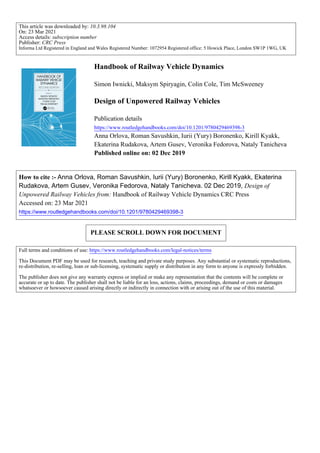
- 30. Downloaded By: 10.3.98.104 At: 18:53 23 Mar 2021; For: 9780429469398, chapter3, 10.1201/9780429469398-3 71 Design of Unpowered Railway Vehicles 3.3.1 Wheelsets A wheelset comprises two wheels rigidly connected by a common axle. The wheelset is supported on bearings mounted on the axle journals. The wheelset provides the following: • The necessary distance between the vehicle and the track • The guidance that determines the motion within the rail gauge, including at curves and switches • The means of transmitting traction and braking forces onto the rails to accelerate and decelerate the vehicle The design of the wheelset depends on the following: • The type of the vehicle (traction or trailing) • The type of braking system used (shoe brake, brake disc on the axle or brake disc on the wheel) • The construction of the wheel centre and the position of bearings on the axle (inside or outside) • The desire to limit higher-frequency forces by using resilient elements between the wheel centre and the tyre The main types of wheelset design are shown in Figure 3.28. Despite the variety of designs, all these wheelsets have two common features: the rigid connection between the wheels through the axle and the cross-sectional profile of the wheel rolling surface, named the wheel profile. In curves, the outer rail will be of a larger radius than the inner rail. This means that a cylindri- cal wheel has to travel further on the outer rail than on the inner rail. As the wheels moving on the inner and outer rails must have the same number of rotations per time unit, such motion cannot occur by pure rolling. To make the distances travelled by the two wheels equal, one or both of them will therefore ‘slip’, thus increasing the rolling resistance and causing wear of wheels and rails. The solution is to machine the rolling surface of wheels to a conical profile with variable inclination angle γ to the axis of the wheelset (see Figure 3.29). The position of the contact point when the wheelset is at a central position on the rails determines the so-called ‘tape circle’, where the diameter of the wheel is measured. On the inner side of the wheel, the conical profile has a flange that prevents derailment and guides the vehicle once the available creep forces have been exhausted. An unrestrained wheelset with conical profiles will move laterally in a curve such that the outer wheel is rolling on a larger radius (due to the cone angle) than the inner one. It can be seen that, for each curve radius, only one value of conicity exists that eliminates slip. As different rail- ways have varying populations of curve radii, the shape of wheel profile that provides minimum slip depends on the features of the track. Railway administrations normally specify allowable wheel profiles for their infrastructure and the degree of wear permitted before re-profiling is required [27,28,29]. Figure 3.30 shows several examples of new wheel profiles. For understanding the dynamic behaviour of a railway vehicle, the conicity of the wheel-rail interface is critical. Conicity is defined as the difference in rolling radii between the wheels for a given lateral shift of the wheelset. Despite the variety of wheel profiles, they have a number of common features. The width of the profile is typically 125 to 135 mm, and flange height for vehicles is typically 28 to 30 mm. The flange inclination angle is normally between 65° and 70°. In the vicinity of the tape circle, the
- 31. Downloaded By: 10.3.98.104 At: 18:53 23 Mar 2021; For: 9780429469398, chapter3, 10.1201/9780429469398-3 72 Handbook of Railway Vehicle Dynamics ɣ is 1:10 or 1:20 for common rollingstock. For high-speed rollingstock, the ɣ is reduced to around 1:40 or 1:50 to prevent hunting. It can be seen from Figure 3.30 that the wheel profile has a relief towards the outer side of the wheel. This is intended to lift the outer side of the wheel off the rail and thus ease the motion on switches. Some modern wheel profiles, particularly for passenger roll- ingstock or heavy haul freight wagons, are not conical but designed instead from a series of radii Tread Flange D Facet Tape circle γ FIGURE 3.29 Main elements of wheel profile. (From Iwnicki, S. (Ed.), Handbook of Railway Vehicle Dynamics, CRC Press, Boca Raton, FL, 2006. With permission.) FIGURE 3.28 Main types of wheelset design: (a) with external and internal journals, (b) with brake discs on the axle and on the wheel and (c) traction wheelsets with asymmetric and symmetric positioning of gears. (1) Axle; (2) wheel; (3) journal; (4) brake disc; and (5) tooth gear. (From Iwnicki, S. (Ed.), Handbook of Railway Vehicle Dynamics, CRC Press, Boca Raton, FL, 2006. With permission.)
- 32. Downloaded By: 10.3.98.104 At: 18:53 23 Mar 2021; For: 9780429469398, chapter3, 10.1201/9780429469398-3 73 Design of Unpowered Railway Vehicles (a) (b) (c) (d) (e) (f) (g) (h) FIGURE 3.30 Common wheel profiles: (a) for freight and passenger railcars (Russia), (b) for freight rail- cars (China), (c) for industrial rollingstock (Russia), (d) for European freight and passenger railcars, (e) and (f) for high-speed trains (Japan), (g) for freight railcars (India) and (h) for high-speed railcars (Russia). (From Iwnicki, S. (Ed.), Handbook of Railway Vehicle Dynamics, CRC Press, Boca Raton, FL, 2006. With permission.)
- 33. Downloaded By: 10.3.98.104 At: 18:53 23 Mar 2021; For: 9780429469398, chapter3, 10.1201/9780429469398-3 74 Handbook of Railway Vehicle Dynamics that approximate a partly worn shape. This is intended to give a more stable shape and prevent the significant changes in conicity that may occur as a conical wheel profile wears. An example of such as profile is the UK P8 wheel profile. For profiles whose shape is not purely conical (either by design or through wear in service), the term equivalent conicity is applied [30]. This is the ratio of the rolling radius difference to twice the lateral displacement of the wheelset: γeq R y = ∆ 2 (3.1) It is important to note that the rolling radius difference is a function of both the wheel and rail shape, and hence, a wheel profile on its own cannot be described as having an equivalent conicity. As the wheel wears, the shape of the profile in operation may alter significantly from the initial design shape, depending upon a large number of factors. These may include the curvature profile of the route, the suspension design, the level of traction and braking forces applied, the average rail profile shape encountered and the lubrication regime. Tread wear (Figure 3.31) will increase the height of the flange and eventually cause it to strike fishplate bolts, etc. If the tread wear causes the profile to become excessively concave (named hollow wear), damaging stresses may arise at the outer side of the wheel and rail and this is known as false flange damage. Flange wear may lead to increase of the flange angle and reduction of the flange thickness. In extreme conditions this could increase the risk of switch splitting derailments. Wheel profiles are generally restored to their design shape by periodic turning on a wheel lathe. This can normally be carried out without the necessity to remove the wheelset from the vehicle. It is clear that contact conditions will vary considerably, depending upon the shape of the wheel and rail profiles. This may take the form of single-point, two-point or conformal contact, as shown in Figure 3.32. One-point contact (a) develops between the conical or tread worn wheel profiles and rounded rail profile. Wheels wear quickly towards the local rail shape. With two-point contact (b), the wheel additionally touches the rail with its flange. In this case, the rolling contact has two dif- ferent radii which causes intensive slip and fast flange wear. Conformal contact (c) appears when the wheel profile and the gauge side of the railhead wear to the extent that their radii in the vicinity of the contact patch become very similar. Many researchers design the optimal combinations of wheel and rail profiles that will provide low wear of both of them as well as reduce the rolling contact fatigue [29,31,32]. FIGURE 3.31 Tread and flange wear. (From Iwnicki, S. (Ed.), Handbook of Railway Vehicle Dynamics, CRC Press, Boca Raton, FL, 2006. With permission.)
- 34. Downloaded By: 10.3.98.104 At: 18:53 23 Mar 2021; For: 9780429469398, chapter3, 10.1201/9780429469398-3 75 Design of Unpowered Railway Vehicles 3.3.2 Axleboxes and Cartridge Type Bearings The axlebox is the device that allows the wheelset to rotate by providing the bearing housing and also the mountings for the primary suspension to attach the wheelset to the bogie or vehicle frame. The axlebox transmits longitudinal, lateral and vertical forces from the wheelset onto the other bogie elements. Axleboxes are classified according to: • Their position on the axle depending on whether the journals are outside or inside the wheel • The bearing type used, either roller or plain bearings The external shape of the axlebox is determined by the method of connection between the axlebox and the bogie frame and aims to achieve uniform distribution of forces on the bearing. Internal construction of the axlebox is determined by the bearing and its sealing method. Axleboxes with plain bearings (see Figure 3.33) consist of housing 1; bearing 2, which is usu- ally made out of alloy with low friction coefficient (e.g., bronze or white metal); bearing shell 3 that transmits the forces from the axlebox housing to the bearing and a lubrication device 4 that lubricates the axle journal. Front and rear seals 5 and 6 prevent dirt and foreign bodies entering FIGURE 3.32 Possible contact situations between the wheel and the rail: (a) one-point contact, (b) two-point contact and (c) conformal contact. (From Iwnicki, S. (Ed.), Handbook of Railway Vehicle Dynamics, CRC Press, Boca Raton, FL, 2006. With permission.) FIGURE 3.33 Construction of axlebox with friction-type bearing. (1) housing; (2) bearing; (3) bearing shell; (4) lubrication device; (5 and 6) front and rear seals. (From Iwnicki, S. (Ed.), Handbook of Railway Vehicle Dynamics, CRC Press, Boca Raton, FL, 2006. With permission.)
- 35. Downloaded By: 10.3.98.104 At: 18:53 23 Mar 2021; For: 9780429469398, chapter3, 10.1201/9780429469398-3 76 Handbook of Railway Vehicle Dynamics the axlebox, while front seal 6 can be removed to monitor the condition of the bearing and add lubricant. Vertical and longitudinal forces are transmitted through the internal surface of the bearing and lateral forces by its faces. Plain bearing axleboxes are now largely obsolete, as they have several serious disadvantages: • High friction coefficient when starting from rest • Poor reliability • Labour-intensive maintenance • Environmental pollution However, from a vehicle dynamic behaviour point of view, axleboxes with plain bearings had cer- tain positive features. In recent years, plain bearing axleboxes that do not require lubrication have been reintroduced on certain types of rollingstock, though their use is still rare. Axleboxes with roller-type bearings (examples shown in Figure 3.34) are classified according to: • The bearing type (cylindrical, conical, spherical) • The number of bearing rows in one bearing (two or one row) • The fitting method (press-fit, shrink-fit and bushing-fit) The main factor that determines the construction of axlebox is the way it experiences the axial forces and distributes the load between the rollers. Cylindrical roller bearings have high dynamic capacity in the radial direction but do not transmit axial forces (Figure 3.34a). Experience in operation of railway rollingstock showed that the faces of rollers can resist lateral forces. However, to do this successfully, it is necessary to regulate not only the diameter but also the length of rollers and the radial and axial clearances. Conical bearings (Figure 3.34d and e) transmit axial forces through the cylindrical surface due to its inclination to the rotation axis. This makes it necessary to keep the tolerances on roller diam- eters and clearances almost an order of magnitude tighter than for cylindrical bearings. In addi- tion, conical bearings have higher friction coefficients compared with the radial roller bearings and therefore generate more heat. This produces higher requirements for seals and grease in conical bearings. Spherical bearings have not been widely applied due to their high cost and lower weight capacity, although they have a significant advantage in providing better distribution of load between the front and rear rows in case of axle bending. Ball bearings are, however, often combined with cylindrical bearings in railway applications to transmit axial forces. High-speed rollingstock often has three bearings in the axlebox – two transmitting radial forces and one (often a ball bearing) working axi- ally (see Figure 3.35). FIGURE 3.34 Constructions of roller bearings: (a) cylindrical double-row, (b) one-row self-alignment, (c) two-row self-alignment, (d) two-row conical and (e) one-row conical (two bearings are shown). (From Iwnicki, S. (Ed.), Handbook of Railway Vehicle Dynamics, CRC Press, Boca Raton, FL, 2006. With permission.)
- 36. Downloaded By: 10.3.98.104 At: 18:53 23 Mar 2021; For: 9780429469398, chapter3, 10.1201/9780429469398-3 77 Design of Unpowered Railway Vehicles Recently, cartridge-type roller bearings gained wide application for higher speeds and axleloads due to many advantages: • Resistance to combined axial and radial loads that guarantees increased mileages between repairs • High accuracy in production that eliminates clearances and reduces vibrations at high rotation speeds • Compact design with smaller external dimensions and mass • Cartridge-type design that does not need disassembling during maintenance but is replaced as one piece • Internal seals, grease and clearances are pre-set during the production and thus greasing and adjustment in operation are excluded The most common cartridge type bearing (Figure 3.36a) consists of the two-row basic bearing: two rows of rollers inside the polymer cages, two cones separated with a spacing ring, one cup on the outside, seals and grease. The basic bearing is a press-fit onto the axle journal having the backing ring with a seal and is then fastened with a washer and bolts (Figure 3.36b). The cup is used as a seat for the adapter. 3.3.3 Wheels Wheels and axles are the most critical parts of the railway rollingstock. Mechanical failure or exceedance of design dimensions cause derailment. Wheels are classified into solid, tyre and assem- bly types, as shown in Figure 3.37. Solid wheels (Figure 3.37a) have three major elements: the tyre, the disc and the hub, and they mainly differ in the shape of the disc. Tyred wheels (Figure 3.37b) have a tyre fitted to the wheel disc that can be removed and replaced when it reaches its maximum turning limit. Wheels may have straight, conical, S-shaped, spoked or corrugated-type discs when viewed in cross-section. A straight disc reduces the weight of the construction and can be shaped such that the metal thickness corresponds to the level of local stress. The conical and S-shape discs serve to increase the flexibility of the wheel, therefore reducing the interaction forces between the wheels and the rails. Corrugated discs have better resistance to lateral bending. The desirability of reducing wheel-rail interaction forces by reducing the unsprung mass has led to development of resilient wheels (Figure 3.37c) that incorporate a layer of material with low FIGURE 3.35 Use of spherical bearings: (a) triple bearing of Japanese high-speed trains and (b) triple bear- ing of French high-speed trains. (From Iwnicki, S. (Ed.), Handbook of Railway Vehicle Dynamics, CRC Press, Boca Raton, FL, 2006. With permission.)
- 37. Downloaded By: 10.3.98.104 At: 18:53 23 Mar 2021; For: 9780429469398, chapter3, 10.1201/9780429469398-3 78 Handbook of Railway Vehicle Dynamics FIGURE 3.36 Cartridge type roller bearing: (a) bearing and (b) its application with adapter. conical wheel S-shaped wheel straight wheel (a) conical wheel spoked wheel corrugated wheel (b) bolted construction with rubbe rlayer with independent rotation (c) FIGURE 3.37 Major types of railway wheels: (a) solid wheels, (b) tyred wheels and (c) assembly wheels. (From Iwnicki, S. (Ed.), Handbook of Railway Vehicle Dynamics, CRC Press, Boca Raton, FL, 2006. With permission.)
- 38. Downloaded By: 10.3.98.104 At: 18:53 23 Mar 2021; For: 9780429469398, chapter3, 10.1201/9780429469398-3 79 Design of Unpowered Railway Vehicles elasticity modulus (rubber or polyurethane). These help to attenuate the higher frequency forces acting at the wheel-rail interface. Improved bearing reliability aroused interest in independently rotating wheels, which provide significant reductions in unsprung mass due to the elimination of the axle. By decoupling the wheels, an independently rotating wheelset inevitably eliminates the majority of wheelset guid- ance forces. Such wheelsets have found application either on variable gauge rollingstock, provid- ing fast transition from one gauge width to another, or on urban rail transport, where a low floor level is necessary. 3.4 DESIGN OF FREIGHT WAGONS BOGIES In most cases, freight wagons use two two-axle bogies per vehicle. Articulated freight wagons can have three or more two-axle bogies, with two neighbouring frames resting on one bogie between them. The majority of freight bogies have single-stage suspension, either between the wheelsets and the bogie frame (similar to passenger bogie primary suspension and often termed ‘axlebox’ suspension) or between the bogie frame and the bolster (similar to passenger bogie secondary suspension and often termed ‘central’ suspension). It can be seen from Figure 3.38 that central suspension makes up approximately 6% more of the designs than axlebox suspension. Some wagons use double suspen- sions similar to passenger bogies to reduce track forces or improve isolation of the load from excess vibrations. 3.4.1 Three-Piece Bogies Bogies with central suspension are common in the countries of the former USSR, the USA, Canada, China, Australia, South America and most countries in Africa, thus outnumbering axlebox and double-suspension bogies by tens of times. Examples of the classical CNII-H3 (type 18-100) Russian bogie and the Barber bogie from the USA are shown in Figures 3.39 and 3.40, respectively. Such bogies are often termed ‘three-piece’ bogies [33]. The frame of a three-piece bogie consists of the bolster and two sideframes that are elastically connected by a coil spring and friction wedge-type central suspension system, which, besides other functions, resists asymmetrical loads and holds the bogie frame square in plane. Such suspension allows independent pitch of the sideframes when passing a large vertical irregularity on one rail, allowing the bogie to safely negotiate relatively poor track. FIGURE 3.38 Proportions of the types of suspension design in freight bogies.
- 39. Downloaded By: 10.3.98.104 At: 18:53 23 Mar 2021; For: 9780429469398, chapter3, 10.1201/9780429469398-3 80 Handbook of Railway Vehicle Dynamics The vehicle body is connected to the bogie with a flat centre bowl and rigid side bearings having clearance in the vertical direction. When moving on straight track, the car body rocks on the centre bowl and does not touch the side bearings, the gravitational force providing recovery to the central position. In curves, the car body contacts the side bearings. The central suspension consists of a set of nested coil springs and the wedge arrangement that provides friction damping in the vertical and lateral directions. The inclination of the friction wedges may vary between designs: in the 18–100 bogie, the angle is 45°, whilst in the Barber bogie, it is 35°. Freight wagons suspensions have to operate under a wide range of load conditions from tare to fully laden, when axle loads can change by more than four times and the load on the spring set more than five times. In the 18–100 bogie, the stiffness of the spring set is independent of the load, which leads to poor ride and increased derailment risk of empty wagons due to small deflections of the springs. For the Barber bogie, a range of suspension spring sets are available for axle loads from 7 to 34 t that include spring sets with bilinear and multi-linear vertical force characteristics. FIGURE 3.39 Type 18–100 three-piece bogie: (a) general view, (b) central suspension schematic and (c) primary ‘suspension’ schematic. (1) Wheelset; (2) sideframe; (3) bolster; (4) braking leverage; (5) centre bowl; (6) rigid side bearings; (7) suspension springs; (8) friction wedge; and (9) axlebox. (From Iwnicki, S. (Ed.), Handbook of Railway Vehicle Dynamics, CRC Press, Boca Raton, FL, 2006. With permission.) FIGURE 3.40 Barber S-2 bogie. (From Iwnicki, S. (Ed.), Handbook of Railway Vehicle Dynamics, CRC Press, Boca Raton, FL, 2006. With permission.)
- 40. Downloaded By: 10.3.98.104 At: 18:53 23 Mar 2021; For: 9780429469398, chapter3, 10.1201/9780429469398-3 81 Design of Unpowered Railway Vehicles The sideframes of a three-piece bogie rest on the wheelsets. In the 18–100 bogie, the bearing is mounted inside the axlebox, whilst the Barber bogie has an adapter between the cylindrical cartridge-type bearing and the pedestal of the sideframe. Clearances between the adapter (or the axlebox) and the sideframe in the longitudinal and lateral directions allow the wheelsets to move in curves and when passing the large horizontal irregularities. Thus, the axlebox unit does not steer the wheelsets but damps their displacements by friction forces. Owing to the absence of a primary suspension, such bogies have a large unsprung mass, which causes increased track forces on short irregularities or rail joints. In curves, the three-piece bogies demonstrate the ‘lozenging’ or ‘warping’ effects, when the two sideframes adopt a parallelogram position (in plan view). In this instance, the wheelsets cannot adopt a radial position in the curve and generate large angles of attack. This leads to constant contact between the high-rail flange of the leading wheelset and the rail, causing high levels of wear [34]. Since classic three-piece bogies were introduced in the 1930s, there have been many advances in their design that deal with the known disadvantages and are explained in detail in [35–37]: • Increase in suspension deflection under the tare wagon as well as under the fully loaded one • Wedge designs that increase the warping stiffness by spatial configuration of inclined surfaces [38] • Introduction of elastic pads in primary suspension to provide steering of wheelsets and reduce unsprung mass • Installation of constant contact side bearings that have an elastic element compressed by the weight of the car body and provide yaw and roll resistance to the car body [39]. 3.4.2 Primary Suspended H-Frame Bogies The Y25 (and similar bogies such as the Y33) are predominantly used on European freight vehi- cles [40]. An example of this bogie is shown in Figure 3.41. FIGURE 3.41 The Y25 bogie: (a) general view, (b) primary suspension schematic (Lenoir damper) and (c) elastic side bearing schematic. (1) Wheelset; (2) rigid H-shaped frame; (3) braking leverage; (4) centre bowl; (5) side bearings; (6) suspension springs; and (7) axlebox. (From Iwnicki, S. (Ed.), Handbook of Railway Vehicle Dynamics, CRC Press, Boca Raton, FL, 2006. With permission.)
- 41. Downloaded By: 10.3.98.104 At: 18:53 23 Mar 2021; For: 9780429469398, chapter3, 10.1201/9780429469398-3 82 Handbook of Railway Vehicle Dynamics The Y25 bogie has a single-stage primary suspension consisting of a set of pairs of nested coil spring (with a bi-linear characteristic for tare/laden ride) and a Lenoir link friction damper (Figure 3.41b) providing vertical and lateral damping. The friction force depends on the vertical load on the spring set, a component of which is transferred to the friction face by the inclined Lenoir link. Derailment safety is improved by the provision of vertical clearance between the inner and outer springs in each pair, giving a lower stiffness in tare than in laden. Whilst improving the ride in both conditions, problems may still arise with the part-laden ride, when the bogie is just resting on the inner ‘load’ spring, making the suspension relatively stiff for the load being carried. The bogie has rigid H-shaped frame that consists of two longitudinal beams, one lateral and two end beams, and may be either cast or fabricated. The connection of the vehicle body is different to the three-piece bogies described previously. The centre bowl has a spherical surface to reduce asymmetric forces on the frame and elastic side bearings without clearance resist the body roll motions (Figure 3.41c). Advances in primary suspended freight bogies [37] include: • Using progressive rubber springs or bell springs instead of coil springs and Lenoir damper • Introducing the additional pusher spring into the Lenoir damper or using double Lenoir links on each of the axleboxes to reduce longitudinal stiffness and facilitate curving • Using wedge type friction damper with four rows of springs 3.4.3 Double-Suspension Bogies In the 1980s, the UK had developed a novel, track-friendly bogie using passenger vehicle technol- ogy. The LTF25 bogie is shown in Figure 3.42 and is described in [41]. The LTF25 bogie was specifically designed to reduce dynamic track forces, and, as part of this, effort was made to reduce the unsprung mass. Small wheels (813 mm diameter) were used and inside axleboxes, giving a 30% reduction in wheelset mass, although this necessitated the use of on- board hotbox detectors. Primary suspension is through steel coil springs, and secondary suspension is through rubber spring elements and hydraulic dampers. The high cost of the LTF25 bogie and concerns about axle fatigue with inboard axleboxes militated against its adoption, but a modified version known as the TF25 bogies (with suspension reduced to only primary) have achieved consid- erable production success. FIGURE 3.42 LTF25 bogie. (From Etwell, M.J.W., J. Rail Rapid Transit, 204, 45–54, 1990. With permission.)