![Citation: Contò, C.; Bianchi, N.
E-Bike Motor Drive: A Review of
Configurations and Capabilities.
Energies 2023, 16, 160. https://
doi.org/10.3390/en16010160
Academic Editor: Adolfo Dannier
Received: 9 November 2022
Revised: 1 December 2022
Accepted: 12 December 2022
Published: 23 December 2022
Copyright: © 2022 by the authors.
Licensee MDPI, Basel, Switzerland.
This article is an open access article
distributed under the terms and
conditions of the Creative Commons
Attribution (CC BY) license (https://
creativecommons.org/licenses/by/
4.0/).
energies
Review
E-Bike Motor Drive: A Review of Configurations
and Capabilities
Chiara Contò * and Nicola Bianchi
Department of Industrial Engineering, University of Padova, Via Gradenigo 6, 35131 Padova, Italy
* Correspondence: chiara.conto@phd.unipd.it
Abstract: In recent years, the mobility sector is undergoing a revolution, which is resulting also into
a worldwide spread of light electric vehicles, such as electric scooters and bicycles. The increasing
public concern about environmental problems further feeds this revolution. Electric-bicycles (or
e-bikes) are a new trend which fits different riders’ needs. In fact, they offer extended range and ease
of use, allowing riders to travel in urban centres, but also to take longer trips. E–bikes are reliable,
easy to ride, affordable, and they help people live and travel a little greener, with a great benefit for
their health. Many Companies (such as Brose, Bafang, Bosch and Shimano) developed performing
e-bike motor drives. However, there is not a detailed general procedure to help the choice and design
of electric bikes, in particular concerning the electric machine. This review focuses on the analysis of
different motors for e-bike application. First, the e-bike system state of art is presented. The pedal-
assist and power-on-demand e-bike system typologies are presented, together with the most popular
parallel configuration and the less common series configuration. Further on, the environmental
resistances are analysed for a traditional bicycle system and then the force balance is extended to
the electric vehicle example. The most common Lithium-ion battery and the battery management
system state of art is discussed, presenting design schemes and typical performances. Concerning
the electrical machine, some electromagnetic design approaches are described, together with some
data on commercial motors. Finite element analysis of a common motor model is carried out and
some experimental tests are presented to highlight their capabilities. Different control strategies are
compared, including innovative solutions and new trends.
Keywords: Permanent Magnet Synchronous Motor (PMSM); synchronous machine; light electric
vehicles; electric bicycle; motor design
1. Introduction
Recently, owing to the increasing public concern about environmental problems, such
as global climate change, various technologies have begun to spread. Particularly, eco-
friendly mobility has attracted increasing attention because it contributes to reducing global
warming. In particular, Electric Vehicles (EVs) are rapidly spreading worldwide. Such a
revolution in mobility also extends to light EVs, such as electric scooters and bicycles.
Electric motor powered bicycles, called electric-bicycles (or e-bikes) [1], are a new trend
which fits different riders needs. They offer greater range and ease of use, allowing travel in
urban centres and longer trips. E-bikes are reliable, easy to ride, affordable, and they help
people live and travel a little greener, with a great benefit for their health [2–4]. Considering
a urban environment, e-bikes allow for a faster travel and reduce parking issues compared
to cars. More importantly, they cut down on fuels consumption and pollution, helping
to improve air quality and the environment. Moreover, people can switch to a healthier
travel solution with the comfort of a reduced physical effort [5]. Electric bicycles also offer
the boost needed to ride much longer or challenging bicycle routes. The assistance of the
electric motor helps overcome hills, slopes and rough terrain, allowing for a smoother ride.
As a result, the young generation of cyclists is embracing this technology, thus making
Energies 2023, 16, 160. https://doi.org/10.3390/en16010160 https://www.mdpi.com/journal/energies](https://image.slidesharecdn.com/energies-16-00160-221223144204-6437f75a/85/energies-16-00160-pdf-1-320.jpg)
![Energies 2023, 16, 160 2 of 34
climbs less difficult and going farther and faster than they could have done with their own
pedal power. Moreover, this new technology helps to get people cycling who could not
ride a traditional bike because of physical aches and pains [6].
E-bikes are currently the most popular bikes on the market and their popularity is
constantly rising. Figure 1 shows the e-bike global market trend, from 2018 to 2028. In
2021, market reached about USD 25 billion. The annual growth rate forecasted is equal to
about 10 percent between 2021 and 2028, reaching USD 48.5 billion in 2028, almost twice
the 2021 market size [7]. Europe accounts for approximately 30% of the e-bike market [8],
dominated by Germany and followed by Netherlands and France [9].
2
018
2
019
2
020
2
021
2
022
2
023
2
024
2
025
2
026
2
027
2
028
0
1
2
3
4
5
·104
year
Million
U.S.
dollars
Figure 1. Projections for the global electric bike market between 2018 and 2028 [7].
This paper deals with e-bike system configurations and capabilities. The design of an
electric bicycle can be divided into three different domains: system level, mechanical and
electrical design [10]. The overall system design includes the choice of the e-bike topology
(series or parallel), the type of electric energy assistance (pedelec or power-on-demand) and
a possible energy regeneration. All these aspects are deepened in Section 2. The mechanical
domain consists in choosing the motor placement and the gear type. Such a topic will
be deepened in Section 3. Finally, the electrical domain includes the energy storage type
choice, discussed in Section 4, and the electrical machine configuration.
For the dissemination of a more eco-friendly mobility, high-performance electrical mo-
tors are required. In particular, motors that exhibit high torque at low speed, and constant
output characteristics over a wide range. Considering this, Permanent Magnet Synchronous
Motors (PMSMs) are the most suitable traction motors. In Section 5 the most recent tech-
nologies about electric motor design are presented, together with some simulation and
experimental results on a PMSM motor.
Many control strategies have been developed over time. Some of them are presented
from Sections 6–10. Other e-bike applications are discussed in Section 12, while conclusions
are drawn in Section 13.
2. E-Bike System
An e-bike can be seen as a light hybrid electric vehicle that combines human and
electric power. The overall e-bike drive system consists of four blocks, as represented in
Figure 2:
• a battery, currently the most popular are low-voltage Lithium-ion batteries;](https://image.slidesharecdn.com/energies-16-00160-221223144204-6437f75a/85/energies-16-00160-pdf-2-320.jpg)
![Energies 2023, 16, 160 3 of 34
• a power converter, which connects the battery to the motor, regulating the current
supplied;
• a controller, which controls the switching based on the duty cycle, according to the
user demand and the battery voltage;
• an electric motor.
Battery Converter
Controller Pedal crank
Motor
Figure 2. Block-scheme of the e-bike system.
E-bikes are classified according to the power that the electric motor can deliver and
the control system. Two categories are defined: the pedal-assist and the power-on-demand
electric bicycle.
The pedal-assist e-bike, also called pedelec, is characterized by an electric motor that
assists the rider while pedalling. The additional torque value depends on the driver effort
and this assistance can be provided up to a maximum speed and a maximum power,
depending on specific regulations of the country. Over short periods of time, higher
power output is allowed. This type of system requires pedalling speed sensors and/or
force sensors.
The power-on-demand e-bike has an electric motor activated by a throttle. Thus, there is
no need to pedal to benefit from the electric motor propulsion.
Considering the overall system, there are two ways to design such a light EV [10]: as a
serial or parallel way.
The parallel case [11], shown in Figure 3a, is the most popular configuration adopted.
The human torque and the motor torque are combined in the mechanical domain via gears.
In the series configuration [12], shown in Figure 3b, the human and electrical machine
torque are coupled in the electrical domain. Thus, the series vehicle is characterized by the
absence of a mechanical transmission: the pedals are connected to a generator electrically
coupled to a battery pack and an electric motor. The double conversion of human power
has the positive effect that optimal cadence can be achieved at all slopes. A high efficiency
can be achieved by keeping the rider operation in its optimal efficiency point all the time,
as a typical series electrical-internal combustion engine hybrid machine.](https://image.slidesharecdn.com/energies-16-00160-221223144204-6437f75a/85/energies-16-00160-pdf-3-320.jpg)
![Energies 2023, 16, 160 4 of 34
Motor
Control system
(ECU)
Battery Converter
Rider input
pedals
Gears
Wheel drive
(a)
Control system
(ECU)
Rider input
pedals
Generator Converter
Battery
Wheel drive
Motor
(b)
Figure 3. Comparison of parallel and serial e-bike configurations. (a) Parallel configuration. (b) Serial
configuration.
Besides the assist type classification, e-bikes can be categorized [2,3] on the basis of
motor type, motor assembly (gear, hub, friction), throttle type (thumb throttle, twist throttle,
push button) and motor placement (front or rear wheel), as examinated in the following.
3. Mechanical Fundamentals
3.1. General Mechanics of a Bicycle
This Section deals with the mechanics and aerodynamics of e-bike [1–3], and in general,
bicycles (powered by human torque). Considering a ride along a tilted surface, the bicycle
is subject to forces represented in Figure 4.
Figure 4. Forces in a bicycle moving uphill.](https://image.slidesharecdn.com/energies-16-00160-221223144204-6437f75a/85/energies-16-00160-pdf-4-320.jpg)
![Energies 2023, 16, 160 5 of 34
The power consumed to drive the bike Ptot is due to overcoming wind resistance Pdrag,
lifting mass up hills Phill and to overcoming frictions Pfriction:
Ptot = Pdrag + Phill + Pfriction (1)
When the riding speed is high (greater than 3 m/s), most of the power is consumed to
overcome wind resistance Pdrag. When the riding speed is low, frictions are predominant
over drag resistance. Differently, on step hills the majority of the power is delivered to
overcome the slope.
Considering the wind drag, its force can be expressed as:
Fdrag =
1
2
· Cd · ρair · A · (vg + vw)2
(2)
where Cd is the drag coefficient (between 0.12 and 1.1 depending on the bicycle and rider
system shape), ρair is the air density (1.225 kg/m3) and A is the frontal area of the mass. To
compute the drag force the relative speed in air is computed as the sum between ground
speed vg and wind vector vw. The power consumed to overcome the wind drag resistance
travelling at a ground speed vg is:
Pdrag =
1
2
· Cd · ρair · A · (vg + vw)2
· vg (3)
The power consumed to carry the total mass M (bicycle and rider) along a hill with
tilt α, considering the weight force component parallel to the ground Fhill = M · g · sin α, is
computed as:
Phill = M · g · sin α · vg (4)
where vg is the vertical speed of the system.
At a very low speed on a level route, power consumption is mainly due to the rolling
resistance. Such a friction depends on the vehicle weight, the type of bearings used
and the type of tires. The friction force on bicycle wheels is Ffric = M · g · Cr, thus the
power consumed to overcome rolling resistance when travelling at a ground speed vg is
computed as:
Pfric = M · g · Cr · vg (5)
where Cr is the rolling resistance coefficient, which depends on friction effects, for example
ground conformation, mass variation or tire pressure (between 0.002 and 0.012). An
approximated computation of the rolling coefficient applied to e-bikes is presented in
Figure 2.1 of [1].
All forces presented describe the resistances to overcome for bicycles in general.
Considering electric bicycles, the sum of the rider pedal power and the power provided by
the electric motor has to satisfy:
Prider + Pmotor ≥ Ptot (6)
A full dynamic model of the bike, including kinematics, tilt and roll dynamics is
reported in [13]. The model equations are then linearized to achieve the transfer functions
and to design the control system.
3.2. Electric Bicycle Solution
The torque produced by a human at the pedal cranks of a bicycle varies through the
complete crank revolution. The pedalling torque peaks reach maximum value at particular
crank angles. This variable cycling torque is not an issue when pedalling at a constant speed
or even during modest acceleration on a flat road, but it becomes significant when pedalling
up a steep hill: the cycling effort and thus the cyclist’s energy consumption becomes
considerable. Difficulties are also observed when starting to cycle from a complete standstill,](https://image.slidesharecdn.com/energies-16-00160-221223144204-6437f75a/85/energies-16-00160-pdf-5-320.jpg)
![Energies 2023, 16, 160 6 of 34
situation faced by using a lower gear to increase torque. However, the uneven production of
torque by the cyclist cannot be smoothed completely by cyclist effort or cycling techniques
alone. Figure 5 shows the human force effectiveness (both legs), as reported in [14,15].
90 180 270 360
0
Figure 5. Human force effectiveness versus pedal crank angle [14,15].
In addition to the several advantages of electric bicycles, there are also some disad-
vantages. Among the others, the added weight to the bicycle due to the additional electric
motor and battery pack and the need to recharge the battery every time after cycling.
Several solutions have been developed to mitigate these drawbacks. In [11] an algorithm is
designed to recover energy from the cyclist during high-efficiency pedalling and return it
during low-efficiency pedalling. By this way, the battery charge is improved up to 25% in
equivalent cycling efficiency.
Power saving concepts to take into account limited available energy in e-bikes have
been also proposed in [16].
In [15], the authors deals with the design of a switched reluctance motor for an electric
bicycle. The typical cycling operations are computed as torque-speed requirement to the
motor and these operating points are plotted in the efficiency map of the motor. Since the
human propulsive torque models is varies as a sine wave (Figure 5), the motor torque is
instantaneously controlled so that the combined total propulsive torque is smooth. The
cyclist’s cadence is measured to vary the motor torque so that the motor provides the
torque difference to achieve a smooth propulsion torque profile. The sinusoidal reference
of the motor torque is in phase offset from the cyclist torque signal, according to the pedal
crank angle.
The switched reluctance motor is also considered for an electric bicycle in [17]. The
authors focus on methods to effectively reduce torque ripple and acoustic noise, which are
the major drawbacks of such a motor, limiting its widespread use. The torque ripple is
reduced defining the phase current waveform to achieve constant torque in the commu-
tation region. This is accomplished by use of a torque sharing function, which divides a
constant torque reference among different phases by defining a reference current profile for
each phase. The total torque is the combination of the torque produced by all active phases,
with the target of obtain a constant torque.
3.3. Load Diagrams
Considering the e-bike electric motor, its torque versus speed diagram has to satisfy
some standard requirements. The maximum rated torque delivered (during over-load
operation) is equal to 100 N m up to the rated speed, about 40 r/min (4.2 rad/s). The
maximum speed that the electric motor reaches is 120 r/min (12.6 rad/s). Such values refer
to the torque and speed delivered to the wheel, i.e., including the gear transmission ratio.
Such a torque-speed characteristic has to interact with the load resistant torque plot.
Load curve represents the resistant torque variation with the speed. Considering the
previously analysed Equations (3)–(5), the resistant torque is equal to:
τload = τdrag + τhill + τfric (7)](https://image.slidesharecdn.com/energies-16-00160-221223144204-6437f75a/85/energies-16-00160-pdf-6-320.jpg)
![Energies 2023, 16, 160 7 of 34
where the drag torque depends quadratically on the speed, considering a zero wind velocity
(vw = 0 m/s):
τdrag =
1
2
· Cd · ρair · A · v2
g (8)
Differently, the torque resistance related to the hill does not depend on the speed,
but only on the ground slope:
τhill = M · g · sin α · vg (9)
Finally, the rolling resistance torque is a constant term that does not depend on either
speed or slope:
τfric = M · g · Cr (10)
Figure 6 shows the load diagram together with the torque versus speed capability of
the electric motor. The human muscular torque is not presented. The drag coefficient is
Cd = 0.6, the frontal area is considered equal to 1 m2, the total mass is M = 100 kg and the
rolling resistance coefficient is Cr = 0.01. The ground slope varies from 0° to 8°. With just
the torque of the electric motor to the wheel, the vehicle can overcome a tilt of 8 degrees.
For a specific ground slope, the difference between the motor torque and the load resistant
torque represents the acceleration torque.
In literature the study of [18] presents the analysis of the human torque delivered
during the e-bike motion, considering different resistance components. Such a torque is
related to the vehicle speed, in order to develop some possible torque control strategies.
The proposed strategies are manual control, proportional control, and assistant control,
respectively.
In [19] operating cycle profiles are measured during actual road tests.
0 2 4 6 8 10 12 14
0
20
40
60
80
100
Speed (rad / s)
Torque
(Nm)
α= 0 °
α= 2 °
α= 4 °
α= 6 °
α= 8 °
Figure 6. Load diagram, motor torque and load torque versus speed for different ground slopes
(without the rider muscular torque).
4. Battery and Charging
4.1. Lithium Batteries
Originally, most of the commercial light EVs were powered by Lead-acid batteries,
that have both low specific energy (low energy density) and low charging current, resulting
in a short range and a long recharging time. Then, Nickel-metal hydride and later Lithium-
ion batteries have come into the market, outperforming the Lead batteries in the specific
energy that is up to five times higher and in the recharging time that is up to three times
shorter [20].](https://image.slidesharecdn.com/energies-16-00160-221223144204-6437f75a/85/energies-16-00160-pdf-7-320.jpg)
![Energies 2023, 16, 160 8 of 34
Besides the very high specific energy, any Lithium-ion cell has the merit of generating
a relatively high voltage (3.7 V for Lithium-ion versus 1.2 V for Nickel-metal hydride or
Nickel-Cadmium). It is a comparatively high value that helps lowering the number of cells
to be connected in series to get the required voltage. In addition, Lithium-ion batteries are
widely used in e-bike applications also due to their high power density, high efficiency, low
self-discharge and long life cycle [21].
In a charged battery, an electromotive force (emf) of electrochemical type arises due
to the different polarities of the reactants (polarization emf). When connecting a load,
the battery acts as an energy generator. The polarization emf produces a flow of electrons
(current) in the load connected to the battery terminals and is responsible for the conversion
of chemical energy into electric energy, with the corresponding delivery of the stored
chemical energy and the discharge of the battery. When connecting an electric energy source,
the battery acts as an user. The polarization emf opposes the flow of electrons (current)
produced by the external source into the battery and is responsible for the conversion of
electric energy into chemical energy, with the corresponding storage of chemical energy
and the charge of the battery.
From the chemical point of view, operation of the batteries is based on a redox reaction,
i.e., a chemical reaction that takes place when a substance undergoes reduction (gain of an
electron), while another element undergoes oxidation (loss of an electron). Redox reactions
of opposite type occur when connecting the battery to an electric load or to an electric
energy source (generator). The redox reaction occurs between two electrodes: the cathode
and the anode. The anode is the electrode where oxidation occurs, the cathode where
reduction occurs.
The charging mechanism of a Lithium-ion battery consists in ions flowing from the
crystal lattice of the anode to the cathode. During discharge, the dissociation of Lithium
ions creates free electrons in the anode, which generates a charge at the positive current
collector. The electrical current generated then flows from the current collector through a
load to the negative current collector (i.e. the cathode). While the battery is discharging
and providing an electric current through the external electric circuit, the anode releases
positively charged Lithium ions to the cathode, generating an ion flow inside of the battery.
Between cathode and anode, an electrolyte favours the Lithium positive ions movement,
while a separator blocks the flow of electrons inside the battery. When plugging in the
device, the opposite reaction happens. Figure 7 shows the simplified schematic of Lithium-
ion cell operation [22].
Figure 7. Schematic of Lithium-ion cell operation [22].
There is a wide variability in the choice of materials to be used in positive electrodes for
Lithium-ion cells. For automotive applications Cobalt compounds are commonly used, due
to the good electrochemical performances, the high energy density obtained, and the high
thermal stability. However, the main problem is that Cobalt is rare, toxic, and expensive.
Performances with different cathodic and anodic materials are exposed in [23].](https://image.slidesharecdn.com/energies-16-00160-221223144204-6437f75a/85/energies-16-00160-pdf-8-320.jpg)
![Energies 2023, 16, 160 9 of 34
Considering the e-bike application, several Lithium-ion cells are series connected to
built the battery pack with the required voltage. The battery voltage is quite low, typically
36 V or 48 V). The resulting current is around 10–20 A in rated condition, reaching 40–50 A
during overload operations, for a limited time. The actual trend is to mount an integrated
battery pack in frame of the bicycle, as represented in the sketch of Figure 8. Integrated
batteries have the great advantage of an enhanced durability, since they are not exposed
to harsh weather conditions and dust, wetness or dirt of the environment. Some typical
e-bike integrated battery specifications are presented in Table 1.
integrated battery
Figure 8. Scheme of a typical integrated battery.
Table 1. Integrated battery specifications for e-bike application.
Parameter Value Unit
Battery voltage 36/48 V
Capacity 11–20 A h
Energy 400–750 W h
Cycle life 800–1000 cycles
Charging time
w/compact charger 50% of the capacity 2.5–4.2 h
100% of the capacity 6.5–8.8 h
Charging time
w/standard charger 50% of the capacity 1.5–2.1 h
100% of the capacity 3.5–5.4 h
Charging time
w/fast charger 50% of the capacity 1–1.4 h
100% of the capacity 2.5–3.7 h
Operation temperature −20–60 °C
Weight 2.9–4.3 kg
4.2. Battery Management System
Besides the very high specific energy, Lithium cells are very sensitive to temperature,
and a cell can be ruined when overcharged, thus they need some management during their
operation. To this purpose, a Battery Management System (BMS) is usually employed to
control battery operation, charge, and discharge [24–27]. This system solves many safety
problems such as overloading, heating in the battery and possible pack explosion. Since it
makes the working system of the battery efficient, it also increases its life.
Figure 9 represents the block scheme of battery pack interfacing the BMS system.](https://image.slidesharecdn.com/energies-16-00160-221223144204-6437f75a/85/energies-16-00160-pdf-9-320.jpg)
![Energies 2023, 16, 160 10 of 34
Capability
estimation
BATTERY PACK
Cell 1
Cell 2
Cell n
M
E
A
S
U
R
E
M
E
N
T
State of Charge
Thermal management
State of Health
V1
V2
T1
T2
Vn
Tn
current
Cell balancing
Cell balancing
BMS
Figure 9. Scheme of battery pack and BMS system [26].
The BMS structure is represented in Figure 10 [25]. It consists of one central Microcon-
troller Control Unit (MCU) and several local Electronic Control Units (ECUs). Each module
must communicate with the main controller that manages all modules work correctly.
CAN-bus module is used for communication. Data FLASH memory module is used for storage
data of measurement. The measurement data can be preserved up to one month. A DC/DC
module is used for transform the 12 V power source into 5 V power supply. In order to
improve the rejection of disturbs, the DC/DC module is an isolated power supply. The
battery current measurement module is used for measuring charge and discharge current of
battery. The battery voltage measurement module is used for measuring voltage of all cells in
series and evaluate the SOC. Temperature measurement module is used for inspecting surface
of all cells. In addition, as a too high temperature on the surface of Li-ion battery would
result in safety problems, the temperature measurement is essential. The central ECU
constantly monitors voltage and temperature of the cells and, when an alarm situation is
detected, it reacts in order to protect the overall system.
SPI
SPI
SPI
I
S
O
L
A
T
I
O
N
I
S
O
L
A
T
I
O
N
MCU
BATTERY
VOLTAGE
MEASUREMENT
MODULE
BATTERY
CURRENT
MEASUREMENT
MODULE
CELLS
VOLTAGE
TEMPERATURE
MEASUREMENT
AND CELLS
VOLTAGE
BALANCE
MODULE
DC/DC MODULE
CAN MODULE
DATA FLASH MEMORY
MODULE
Figure 10. BMS structure [25].](https://image.slidesharecdn.com/energies-16-00160-221223144204-6437f75a/85/energies-16-00160-pdf-10-320.jpg)
![Energies 2023, 16, 160 11 of 34
Lithium-ion battery system has a high requirement on cell voltage balance. In fact,
even two cells of the same model and from the same manufacturer are not identical.
There are always slight differences in SOC, voltage, current, impedance, and temperature
characteristics. If the SOC of each cells is not periodically equalized, or balanced, such cells
will undergo over-charge or over-discharge, leading to damage, and eventually complete
battery stack failure. BMS will monitor the parameters and determine battery SOC, state of
health and maintains the system in accurate, reliable and balanced state and also determines
the life span of a battery [26]. In particular battery cell balancing is carried out by two
methods, passive and active [27,28].
With the passive cell balancing approach, the cell energy in excess is dissipated through
resistors (in form of heat), as represented in Figure 11a. Passive cell balancing technique is
easy to execute, but less effective and should not be used during discharging. It is possible
to adopt a fixed shunt resistor, continuously bypassing the current and limiting the voltage
by varying the resistor. This is a simple and cheap approach, but it is suitable only for a
small number of cells, it does not allow for a controlled operation and the continuous energy
dissipation increases the heat generation and reduces the battery pack life. Alternatively,
a controlled shunt resistor can be adopted, as in the example of Figure 11a. Controlled
switches/relays are used instead of continuously discharging higher charged cells. This is
a simple, more efficient and reliable approach, yet still implies energy dissipation in heat,
thus lifetime reduction, and it is useful only during charging.
Voltage
measurement
and
balancing
unit
Cn
Rdischarge
C2
Rdischarge
C1
Rdischarge
(a)
Voltage measurement and
balancing unit
Bn
C1
B2
C2
B1
Cn-1
IS
B3
(b)
Figure 11. Scheme of passive and active cell balancing. (a) Passive cell balancing. (b) Active cell
balancing.
The active cell balancing approach uses capacitive or inductive charge storage in order
to transfer the excessive energy from a high-charge cell to a low-charge cell. By this way,
imbalance between cells is regulated: more crucial SOC cells electric energy is transferred
to lower SOC cells, with no damage and no energy dissipation in heat. This method
maximizes the battery available power and is more effective and efficient than the passive
balancing technique.
Active cell balancing topologies include cell bypass, cell-to-cell, cell-to-pack, and pack-
to-cell methods.](https://image.slidesharecdn.com/energies-16-00160-221223144204-6437f75a/85/energies-16-00160-pdf-11-320.jpg)
![Energies 2023, 16, 160 12 of 34
• The cell bypass method consists in making the current bypassing the cells that have
reached a crucial SOC value. The bypassed current continues flowing through the
remaining cells until they reach the maximum SOC as well. Cell bypass techniques are
easy to implement and relatively low in cost. However, they are effective only toward
the end of the charging process when one or more cells have reached maximum SOC.
• Cell-to-cell methods consist in transferring the extra energy stored in a cell to adjacent
cells, if they have lower stored energy. Even if this method is more efficient than cell
bypass, it is complex to implement and slow.
• In cell-to-pack equalization, the most-charged cell energy is equally subdivided between
the remaining cells in the pack.
• Pack-to-cell method is the complementary technology of cell-to-pack. Energy is trans-
ferred from the entire pack to the least charged cell. Both cell-to-pack and pack-to-cell
are lower in efficiency than cell bypass and cell-to-cell, and their complexity is rela-
tively high.
Figure 11b shows an example of cell-to-cell active balancing realized by means of flying
capacitors (C1, C2...Cn−1). A switch structure allows for various capacitors-to-batteries
connections, depending on the balancing conditions. At the beginning, the capacitor is
connected to charge the cell with the higher voltage. Then, the capacitor is connected to
discharge the lower voltage cell. Besides the good charge balancing, this method allows
energy transfer only between adjacent cells and it causes losses during charging and
discharging of the capacitor.
4.3. Charge
Battery charging is playing an important role in the BMS, since charging profiles have
a strong influence on the battery performance and life cycles. Many charging algorithms
have been developed and implemented. Some popular charging algorithms include the
Constant Current and Constant Voltage (CC-CV) [29–31], the pulse charging [32], and the
Sinusoidal Ripple-Current (SRC) charging algorithms [33,34] have been used to charge the
Lithium-ion batteries.
Under the CC-CV charging algorithm, a constant controlled current is applied to
charge the battery until the battery voltage reaches a predefined maximum value. Then,
the charging voltage is maintained constant at this level, and the charging current is reduced
exponentially. When the charging current drops to a cut-off current limit, the charging
process is terminated. Figure 12 shows the voltage and current evolution in time when
CC-CV charging is carried out. Based on the charging current in the CC mode, the total
charging time is varied from 1 h to 2.5 h. In general, the lower the charging current of the
CC mode, the higher the charging efficiency and longer the charging time and the battery
life. Such a charging algorithm is widely used to charge Li-ion batteries due to its simplicity
and easy implementation, even if it requires a long charging time and it causes a large
thermal rising while applying a high charging current, reducing the life cycle of the battery.
When the pulse charge is carried out, the battery voltage is kept constant for the entire
charging process while the frequency or duty cycle of the pulse charging current is changed.
Such a method is faster and more efficient than CC-CV charging for Li-ion batteries.
Recently, the SRC charging algorithm has also been paid attention to increase the
battery lifetime. The charging current consisting of two components: a DC component and
an AC ripple one. The magnitude and frequency of the ripple component are optimized
timely to minimize the internal impedance of Li-ion batteries. Under the minimal internal
impedance condition, the battery temperature during charge is reduced, so both power
and energy efficiencies of the charging process are improved.
However, both pulse charging and SRC charging algorithms have some disadvantages
including complicated implementation, bulky size, and high cost. This makes the CC-CV
method more popular in actual applications.](https://image.slidesharecdn.com/energies-16-00160-221223144204-6437f75a/85/energies-16-00160-pdf-12-320.jpg)
![Energies 2023, 16, 160 13 of 34
Charging current
Battery voltage
Time
CV
CC
Figure 12. Current and voltage evolution during the CC-CV charging.
5. Electric Motors for E-Bike Application
This Section deals with the state of art of the electric motor for e-bike application.
Figure 13 shows possible motor locations on the e-bike structure.
Front wheel hub motors are convenient for maintenance because they can be easily
installed and removed and it creates a better weight balance in the bike with respect to
rear wheel motor. However, some disadvantages of such a configuration are the possible
front wheel slippage, the difficulty in e-bike controlling and steering, and generally a lower
power than that of a rear wheel hub motor.
Unlike a front wheel hub motor, a rear wheel hub motor does not seem to cause wheel
slippage because its weight is distributed at the rear of the e-bike. However, locating the
motor on the rear wheel hub causes an imbalance between the rear and front of the bike.
A mid-drive motor is located in a low and centred position of the e-bike, creating a better
weight balance than front and rear wheel hub motors. Compared with hub motors of the
same power, mid-drive motors are generally smaller and can be directly integrated into the
frame of the bike. Furthermore, mid-drive motors have better hill-climbing characteristics
than hub motors with a similar power, even though they require custom designed frames
when integrated, and they are usually more expensive.
(a) (b) (c)
Figure 13. Possible locations of motor on e-bikes. (a) Front wheel hub-motor. (b) Rear wheel
hub-motor. (c) Mid-drive motor.
Concerning the electrical machine, main technologies include brushless dc or brushless
ac motors, that will be described in the next Subsections.
5.1. Brushless DC Motors
In the past e-bikes were typically equipped with brushed dc or brushless dc (BLDC)
electric motors [3,20,35,36]. The brushed dc motor, even if very popular in early e-bike mod-
els, has been gradually replaced by the BLDC motor. Brushed dc motors are more robust
and relatively cheap compared with BLDC motors. However, the BLDC motor has higher
reliability and power density, thus smaller dimensions. In addition, brushed dc motors
produce higher noise, they are heavier, and require relatively frequent maintenance service.](https://image.slidesharecdn.com/energies-16-00160-221223144204-6437f75a/85/energies-16-00160-pdf-13-320.jpg)
![Energies 2023, 16, 160 14 of 34
Brushless motors are synchronous motors characterized by a magnetization field
produced by Permanent Magnets (PMs) on the rotor. The armature windings are positioned
on the stator to avoid using of any sliding connection. Torque originates from the interaction
of the magnetization field with the (armature) field produced by the current flowing into the
stator windings. When the armature current supplied is a dc current, the brushless machine
is called BLDC motor. Figure 14 shows the fundamental block scheme of a BLDC motor.
DC
motor
Control system
DC supply Static
Converter
Vehicle
Sensor signals
(feedbacks)
Control demand
(reference)
Figure 14. BLDC motor scheme.
BLDC motor merits are its simple and robust electromagnetic structure, its easy control,
its great power ratio and that it requires a position transducer set with a resolution of 120°.
However, BLDC motor drawbacks include the phase current commutation process, the high
torque ripple and the torque-speed characteristic drop at high speeds.
5.2. Permanent Magnet Synchronous Motors
The actual trend is to develop high-performance e-bike traction motors that exhibit
high torque density, especially at low speeds. Thus Permanent Magnet Synchronous Motors
(PMSMs) are spreading worldwide. The PMSM is an AC electric motor characterized by a
rotation of the shaft synchronized with the frequency of the field associated to the stator
winding (armature field), generated by the current supplied. The rotor magnetizing flux
interacts with the stator armature field, which is generated by an AC winding. To satisfy the
high power density constraint, high-energy rare-earth PMs, such as NdFeB or SmCo [37],
represent a key technology for the rotor field design.
5.2.1. Rotor Geometry
Different rotor design solutions can be adopted: the Surface-mounted PM (SPM)
motor of Figure 15a, the Interior PM (IPM) motor of Figure 15b and the IPM spoke motor
of Figure 15c.
(a) (b) (c)
Figure 15. Rotor geometries without shaping. (a) Surface-mounted PM. (b) Interior PM. (c) Interior
PM spoke-type.](https://image.slidesharecdn.com/energies-16-00160-221223144204-6437f75a/85/energies-16-00160-pdf-14-320.jpg)
![Energies 2023, 16, 160 15 of 34
The SPM geometry is mainly adopted when the motor is designed with an outer
rotor, as shown in Figure 16. This is due to the limited space available in the rotating part.
Such a solution is adopted in light electric vehicles with a wheel hub motor, that can be
characterized by IPM geometry as well [38]. A single planetary gearbox connects the rotor
to the wheel.
Figure 16. SPM motor in a wheel hub (18−slots/20−poles configuration).
In inner rotor motors the IPM configuration is preferred. Such a solution is adopted
with crank motor drives, connected to the chain ring by using a two-stage gearbox.
Comparing the torque density, IPM machines theoretically exhibit a higher torque than
SPM machines [39–42]. In fact, the torque has two components: one due to the interaction
between PM flux and stator current, another due to rotor anisotropy, that is, the difference
between the direct- and quadrature-axis inductances (due to the changing reluctance value
along the rotor, from the stator point of view). The SPM machines are characterised by
an isotropic rotor (PMs are located on the rotor surface, i.e., the reluctance from the stator
point of view does not change), so that only the first torque term is produced. In the IPM
machines, the rotor is anisotropic (PMs are buried in the rotor core, i.e., the reluctance from
the stator point of view varies), thus also the reluctance torque component is expected.
However, the rotor anisotropy is low in IPM motors for e-bike application, thus the second
term is almost negligible. This is due to the following reasons:
• the typical high number of poles: the higher the number of poles, the lower the
saliency [43];
• the small size of the motor: the air gap and the leakage fluxes are high in relative
terms;
• if the fractional-slot winding solution is adopted to reduce the copper, the rotor
saliency decreases [44].
Furthermore, a PM mechanically inserted in the rotor prevents magnet scattering at
high speeds and exhibits equal mechanical and electrical air-gap length.
5.2.2. Fractional-Slot Stator Winding
In the majority of e-bike applications, fractional-slot stator windings with non- over-
lapped coils are adopted [45–47]. They are characterized by a non-integral number of
slots per poles and per phase. Fractional-slot motors are usually characterized by a high
number of parallel paths, according to the high currents required, and they are suitable for
machines with high number of poles [48]. In addition, the non-overlapped coil windings
are characterized by reduced end-winding lengths, thus lower copper weight and Joule
losses [49]. Moreover, fractional-slot machines have a phase inductance higher than the
corresponding integral-slot machine. As a result, the flux-weakening capability of the
machine is increased [50] and the short-circuit current in the event of fault is reduced. Since
winding phases are physically and magnetically separated the fault in one phase is not](https://image.slidesharecdn.com/energies-16-00160-221223144204-6437f75a/85/energies-16-00160-pdf-15-320.jpg)
![Energies 2023, 16, 160 16 of 34
propagated to other phases. Thus, the fault-tolerance of fractional-slot windings is im-
proved [51]. However, the torque ripple is higher and some solutions exhibit low winding
factor [49] or Magneto Motive Forces (MMF) sub-harmonics which cause additional rotor
losses and torque ripple [52].
Table 2 compares different commercial motors typologies, including Bosch, Bafang,
Brose and Shimano e-bike electric motors. They are all PM motors, in particular IPM
motors, some with the radial flux density (radial IPM) and others with the spoke-type
geometry (spoke IPM). Only Bosch motor is characterized by a distributed hairpin winding
that is not a fractional-slot type. Such a typology will be discussed in the next Subsection.
The majority of companies employ fractional-slot machines, i.e., the number of slots
per pole per phase is not an integer number. In particular the number of slots per pole per
phase of Bafang motor is 1/2, Brose motor is a 2/5 configuration and Shimano motor a 2/7
typology.
Table 2. Motor typology of different commercial PM machines.
Parameter Bosch Bafang Brose Shimano
Type of motor spoke IPM radial IPM radial IPM spoke IPM
Number of slots Qs 48 12 12 12
Number of poles 2p 16 8 10 14
Winding typology hairpin concentrated concentrated concentrated
distributed fractional-slot fractional-slot fractional-slot
Since the 12−slots / 10−poles and the 12−slots / 14−poles configuration are equiva-
lent in terms of field waveform, the 12−slots / 10−poles configuration is analysed hereafter
as an example. The star of slots and winding connections are represented in Figure 17.
Phase A is identified with the yellow colour, phase B with the pink colour and phase C
with the orange colour.
1
2
3
4
5
6
7
8
9
10
11
12
(a) (b)
Figure 17. Star of slots and winding connections for 12−slots / 10−poles motor. (a) Star of slots. (b)
Connections.
A two-dimensional finite element analysis is carried out through FEMM 4.2 software.
The 12−slots / 10−poles motor model analysed is characterized by an IPM spoke-type
rotor. Figure 18 shows the no-load flux lines and flux density of the motor. It is worth
noting that the radial force on the rotor remains balanced.](https://image.slidesharecdn.com/energies-16-00160-221223144204-6437f75a/85/energies-16-00160-pdf-16-320.jpg)
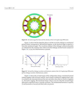
![Energies 2023, 16, 160 19 of 34
This experimental result confirms the flux-linkage analysis of the 12/10 configuration
(Figure 19).
0 18 36 54 72
−4
−2
0
2
4
Rotor position (deg)
EMF
(V)
(a)
0 1 2 3 4 5 6 7 8 9
0
1
2
3
4
Harmonic Order
Harmonic
Amplitude
(V)
(b)
Figure 23. No-load EMF waveform and harmonic content of the 12/10 spoke-type PM motor,
experimental results. (a) Flux-linkage waveform. (b) Harmonic content.
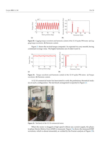
When the motor is supplied by the Maximum Torque Per Ampere (MTPA) current
the torque versus rotor position is measured. Figure 24 shows the very smooth torque
waveform, which is almost constant.
0 18 36 54 72
0
0.6
1.2
1.8
Rotor position (deg)
Torque
(Nm)
(a)
0 5 10 15 20
0
0.6
1.2
1.8
Harmonic Order
Harmonic
Amplitude
(b)
Figure 24. Torque waveform and harmonic content of the 12/10 spoke-type PM motor, experimen-
tal results. (a) Torque waveform. (b) Harmonic content.
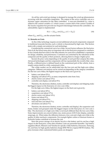
Varying the direct- and quadrature-axis currents Id and Iq the motor performance can
be defined in the whole (Id, Iq) plane. Figure 25 shows the torque, current and speed limit
curves obtained for the 12/10 motor.
Considering the theoretical definition of the output torque:
τ = 3/2 · p · [Λm · Iq + (Ld − Lq) · Id] (11)
it represents a family of hyperbolae in the (Id, Iq) plane. However, the resulting torque
curves of Figure 25 (black bold lines) are almost straight lines, similar to those obtained
with a SPM motor. This is a further confirmation that the rotor saliency and the reluctance
torque term are negligible, as remarked in Section 5.2.1.
The current limits are represented by circumferences with radius Î:
I2
d + I2
q = Î2
(12)
Different current circles can be represented. The maximum torque generated for a
given current amplitude can be identified as the torque contour line tangent to such a
current limit circumference. The red curve represents the MTPA trajectory (i.e., MTPA
computed for different current amplitudes). All motors exhibit an MTPA trajectory very
similar to the SPM motor. Thus, the control can be simplified imposing only q-axis current
supply (i.e., Id = 0, Iq = Î).](https://image.slidesharecdn.com/energies-16-00160-221223144204-6437f75a/85/energies-16-00160-pdf-19-320.jpg)
![Energies 2023, 16, 160 21 of 34
0 1 000 2 000 3 000 4 000 5 000 6 000
0
1
2
3
Speed (r/min)
Torque
(N
m)
5 10 15 20 25
(a)
0 1 000 2 000 3 000 4 000 5 000 6 000
0
200
400
600
800
Speed (r/min)
Power
(W)
(b)
Figure 26. Torque and power versus speed. (a) Torque versus speed. (b) Power versus speed.
5.2.3. Distributed Hairpin Windings
In applications as e-bikes, one of the most important requirements is the high torque
density of the electric motor. For a given motor volume, the motor torque increases
proportionally to the air gap flux density (as discussed above) and the operating current.
However, due to constraints on the motor cooling system, a simple increase of the current,
or the current density in the wires, is not feasible.
Following the actual trend in designing traction motors for automotive applications,
a solution is the adoption of hairpin windings, which yields to higher slot fill factor (i.e., the
ratio between the total copper in slot and the slot area), adopting conductors with higher
cross section area. Hairpin technology allows having a slot fill factor even higher than
50% with respect to traditional round wire windings. Figure 27 shows a commercial e-bike
motor adopting hairpin coils in the stator winding.
Figure 27. Bosch motor adopting hairpin winding [53].](https://image.slidesharecdn.com/energies-16-00160-221223144204-6437f75a/85/energies-16-00160-pdf-21-320.jpg)
![Energies 2023, 16, 160 22 of 34
For given Joule losses, a higher fill factor leads to a higher torque density. The hairpin
technology is gaining attention not only for its high slot fill factor, but also for its good
heat dissipation. Figure 28 shows the comparison between the heat transfer of a winding
with non-overlapped coil and the hairpin winding. In this map, the same Joule losses are
imposed. The higher temperature rise in the first stator winding is evident.
Temp.
rise (K)
40
30
(a)
Temp.
rise (K)
40
30
(b)
Figure 28. IPM spoke heat analysis with different stator windings. (a) Non-overlapped coil windings.
(b) Hairpin windings.
Despite all advantages described above, hairpin winding losses may be higher at
high speed, due to non-uniform distribution of currents [54]. However, the conductor
cross section area is quite reduced in this small-size motor so that the additional losses are
moderate. To the aim of their reduction, particular care is given to the winding design,
with proper parallel paths and wires transposition [55].
5.3. Other Motor Typologies
Other types of ac motors, namely the induction machine, switched reluctance and
other synchronous motors have not gained popularity yet.
The induction machine, although cheaper and more reliable, has the disadvantages of
lower torque density and lower efficiency. Thus its application in small electric vehicles,
such as an e-bike, is not very popular. One example using induction machine is shown
in [56].
Another possibility is to employ a switched reluctance motor [57]. In its classical form
it offers better fault tolerance, cost and easier sensorless control, while its disadvantages
are lower efficiency, torque density, noise and larger torque ripple in comparison to the
brushless motor.
Among synchronous motors, also the reluctance machine has been considered for light
EV applications [58,59]. However, such a machine is characterized by a lower power density
than PM synchronous motors, thus its volume has to be higher to achieve the required
performance. The actual trend is to enhance the light EV performance adopting PMs.
A comparative study of different motor geometries is presented in [60]. The double-
stator switched reluctance machine analysed is able to meet and exceed the high torque
(power) performance of an IPM motor at a very competitive cost, using a feasible thermal
management system.
5.4. Stator Terminals Connection
Concerning the stator winding terminals connection, there are two possibilities: the
delta-connection and the star-connection, represented in Figure 29.](https://image.slidesharecdn.com/energies-16-00160-221223144204-6437f75a/85/energies-16-00160-pdf-22-320.jpg)
![Energies 2023, 16, 160 23 of 34
(a) (b) (c)
Figure 29. Delta and star connections. (a) Delta-connection. (b) Star-connection. (c) Circulating
current.
Delta-connected stator windings are often used in mass production of small PMSMs.
In comparison to star-connected stator windings, a delta-connected system has the ad-
vantage of a cheaper manufacturing. However, motors with such a winding system have
additional losses caused by the zero-sequence current component circulating in the circuit,
as represented in Figure 29c.
In [61] losses of a delta-connected PMSM for pedelec application are analysed and
compared with the same motor with a star connection. In delta-connected machine the
additional copper losses are around 6% compared to those generated by the first order
current harmonic. In the nominal operating point the efficiency of the delta-connected
machine is 0.6% smaller, while it is up to 4% smaller in other operating points.
6. Standard Control Methods
Considering commercial pedelec, conventional assisted power methods can be classified
in two groups [62].
The first one is the constant-assisted power method. The rider is assisted by the motor
with a predetermined constant power. A predefined paddle torque is sensed, i.e., the rider
needs assisted power to move the pedelec forward. This method is simple to implement.
However, the same predefined assisted power is provided without considering the riding
environment and the rider physical condition. Therefore the comfort and the safety of the
rider might not be guaranteed.
The second group is the proportion-assisted power method. According to the bike
velocity v, the assisted power ratio (PR) can be expressed as follows
PR =
1, v ≤ v0
1 − k · (v − v0), v0 < v < vmax
0, v ≥ vmax
(14)
If the vehicle velocity v is lower than a predefined velocity v0, the assisted power
provides the same power as the rider power. Over such a speed, PR gradually decreases
according to the parameter k which is chosen to attenuate the assisted power ratio. It
is defined as the inverse of vmax − v0. The motor assisted power is PR multiplied by the
rider power. At last, if the vehicle velocity v is higher than the maximum allowed velocity
vmax, the assisted power is zero. Typical values are vmax = 25 km/h, v0 = 15 km/h, and
k = 0.1. Figure 30 shows the behaviours of the assisted power ratio PR as a function of the
bike velocity.](https://image.slidesharecdn.com/energies-16-00160-221223144204-6437f75a/85/energies-16-00160-pdf-23-320.jpg)
![Energies 2023, 16, 160 24 of 34
PR
v (km/h)
vmax
v'
1
0
Figure 30. Assisted power ratio PR as a function of the velocity v.
A control technique based on disturbance observers is described in [63]. It is able to
adapt to load and road slope.
A control system for a 350 W 3-phase brushless DC motor supplied by a 36 V 5.5 Ah
Li-Ion battery pack is described in [64].
Similarly, model, simulations and measurements are reported in [65].
7. Standard Control Implementations
In [66] an integrated driving-braking control is presented. It is essentially based on
the proportional-integral-derivative (PID) control. A brushless DC hub motor is controlled
by means of the field oriented control for both driving and braking actions.
Using a DC motor, some simulation results are reported in [67]. An ATMEGA-32
microcontroller is used to regulate the analog input from the throttle in an e-bike in [15].
Similarly, a control drive for a brushless DC hub motor is also described in [68], based on
an Arduino board. Simulations and description of the full system are reported in [69].
Similar studies have been carried out on scooter, as in [70].
8. Advanced Control Strategies
8.1. Reinforcement-Learning
In [62] a reinforcement learning is proposed to provide assisted power with comfort of
ride. The agent of the RL takes a sequence of action, i.e., different levels of assisted power,
in the nondeterministic environment of pedelec riding and receives rewards for its actions
in trying to solve the comfort-of-ride problem. After a set of trial-and-error steps, the RL
agent learns the best sequence of action that achieves the comfort of ride for rider. The first
purpose is to satisfy the predetermined quality-of-riding. In the situation of pedelec it is
often complex, since the rider pedal force varies with different road types and the rider
physical conditions in a non deterministic way. Therefore a correct input/output mapping
for electric-assisted power is hard to provide.
A second purpose of the algorithm is to maximize the energy utilization of the battery.
8.2. Fault Diagnosis
As for other electric devices, different techniques to detect faults can be adopted.
In [71] a fault diagnosis approach is described for pedelec drive units. A data-driven
approach for the detection of faults in mechanical components maximizes the information
content of the signals that are already available in the drive unit, avoiding the addition of
other sensors. Support Vector Machine is adopted by the authors, which is a supervised
learning algorithm. The key objective is to construct a hyperplane that separates two
classes, so that the margin is maximum between the hyperplane and the closest data points
of the training set, which are called support vectors. N input vectors xn ∈ <N form the
training set, with target values yn ∈ {−1, 1}. Defining a fixed feature-space transformation,
φ(x), the hyperplane that separates the two classes is given by
y(x) = wT
φ(x) + b = 0 (15)](https://image.slidesharecdn.com/energies-16-00160-221223144204-6437f75a/85/energies-16-00160-pdf-24-320.jpg)
![Energies 2023, 16, 160 25 of 34
where w ∈ <N is a weight vector and b is the bias. The optimal solution requires to
minimize ||w||2. The authors proved that the algorithm is able to identify malfunctions on
systems after a training stage.
8.3. Fuzzy Logic Control
Some authors deal with the control of the electric bike by means of a fuzzy logic
approach.
Figure 31 reports the scheme proposed in [72], where the expected velocity v∗ is
compared to the actual bike velocity vbike (which is linked to the angular speed ωm by
means of the wheel radius Rw). The input to the fuzzy logic system are the angular speed
and its rate of change, the rider torque and its rate of change, the motor current (which is
proportional to the motor torque) and its rate of change.
-
+ ω
Rw
rider
control
bike
dynamic
fuzzy logic
control
electric
motor
d
dt
d
dt
-
+
vref
vbike
∆ω
i
V
τr
∆τr
τm
+
RIDER ACTIONS
FUZZY CONTROL
BIKE DYNAMIC
τr
Figure 31. Scheme of the fuzzy control system [72].
Typical membership functions, as sketched in Figure 32, are adopted to manage the
inputs and obtain the output. The latter corresponds to the voltage command to the motor.
out
in
N Z PS
N = negative
Z = zero
PS = positive small
PB = positive big
PB
1
0
Figure 32. Typical membership function.
A fuzzy logic approach is also adopted for an autonomous dynamic balance of a
running electrical bicycle in [73]. To deal with the huge uncertainties of the bicycle system
caused by different ground conditions and gusts of wind a fuzzy sliding-mode under
actuated control is proposed. The purpose of the strategy employed is twofold: (i) to
control the bike centre of gravity (as a pendulum), (ii) to control the angle of the bike
steering handle. An additional variable is the lean angle. The proposed system produces
three outputs affecting the dynamic balance of the electrical bicycle: the bike pendulum
angle, the the steering angle and the lean angle with respect to the gravity direction of the
bicycle in motion.
Fuzzy logic control is used for an electric bike derived reproducing a normal pedal
powered bicycle is also given in [74]. Fuzzy control is also used in [75] where a kid cycling
is described by means of illustrative rules. Again, a soft-starting method brushless DC
motor in an electric bicycle is reported in [76].
9. Control Interacting with the Rider
There are many studies dealing with the interaction between the power motor assis-
tance and the cyclist, that can be defined as a human rider synergic control.](https://image.slidesharecdn.com/energies-16-00160-221223144204-6437f75a/85/energies-16-00160-pdf-25-320.jpg)
![Energies 2023, 16, 160 26 of 34
For this purpose a particular control strategy is proposed in [11], which is based three
parameters: (a) an equivalent cycling efficiency based on oxygen consumption, that is
ad hoc-defined, (b) a dynamic model for the state of fatigue, including the maximum
isometric force (static force without movement of the muscles), i.e., maximum voluntary
contraction, and (c) heart rate measurements. A control-oriented analysis of the rider
metabolic efficiency is carried out to guide the design of the control algorithm. The idea
is to recover energy from the cyclist during high-efficiency pedalling and return it during
low-efficiency pedalling. It reaches an improvement up to 25 % in equivalent cycling
efficiency and a reduction in peak heart rate and state of fatigue during a urban cycling.
In [13] the authors focus on the control of high speed bicycles, based on the bike
shapes designed by Weaver. The peak speed was 112 km/h during a race in Nevada. An
automated steering controllers for these high-speed bikes is studied. Because of limitations
in human capability, roll control of the bike was getting difficult at higher speeds. They
observed that unexpected wind gusts tends to flip the bike over.
10. Chain-Less Bike Solutions
A series hybrid electric bicycle is proposed in [12]. The cyclist powers an electric
generator that in turn supplies the electric motor and a battery pack. The authors claim
that this e-bike achieve a high efficiency by keeping the rider in its optimal efficiency point
all the time regardless of the bicycle velocity. However, they highlight some challenging
items: (i) how to provide a natural pedalling feeling (especially at low cadence or when
starting) and (ii) how really optimize the vehicle efficiency.
A bilateral control is proposed to the aim of managing the level of assistance while
providing a natural feeling in a systematic way. The generator has to be controlled to
emulate the desired inertia, so as to give satisfactory feeling at the pedal and also for
the vehicle dynamics. The objective is to replicate at the generator, the behaviour of
the motor, and vice versa. An algorithm is studied to control the bike and to provide a
natural pedalling.
The rider torque and speed have to be linked to the load torque and speed by a
relationship as
τped
ωped
=
K1 0
0 ρ/K1
·
τload
ωload
(16)
where K1 corresponds to the traditional transmission ratio between the pedal and the
traction wheel, and ρ is an assistance factor operating as a torque scaling factor.
Bike Emulator
A pedalling experience can be dynamically simulated by means of a bike emulator [77].
A chain-less series bicycle is considered, controlling the electric generator connected to the
pedals. The electric machine is connected to the pedals to enhance a virtual bike driveline
emulation. The authors focus on reproducing the effect of the freewheel mechanism,
which makes the torque transmission unidirectional: the transmission disengages when
the pedals rotate at a lower rate than the wheel (reduced to the pedal shaft). The proposed
motor control strategy is based on two concurrent controllers that simultaneously operate:
cadence and torque. An integration strategy selects which controller is active, because of
the single controllable input that is the motor voltage. The designed integration strategy
guarantees a smooth interchange between the two controllers and copes with the wind-up
phenomenon that affects the deactivated controller.
The controller integration law is achieved taking the minimum between the two
control variables, thus selecting the correct control action automatically:
u(t) = min{u1(t), u2(t)} (17)
without needs of additional switching and guaranteeing bump-less transitions between the
two control actions.](https://image.slidesharecdn.com/energies-16-00160-221223144204-6437f75a/85/energies-16-00160-pdf-26-320.jpg)
![Energies 2023, 16, 160 28 of 34
Table 3 shows battery cost comparison for some famous companies. The reference
parameter is the energy in W h, thus costs are related to the energy, resulting measured in
$/Wh. Other battery suppliers such as Panasonic, Samsung, LG, and Sony offer lower rela-
tive prices (around 0.7 $/W h), since they do not produce specifically e-bike battery packs.
Table 3. E-bike battery cost.
Battery Pack Energy Price Relative Price
Wh $ $/Wh
Bosch Power Pack 500 500 ≈900 ≈1.8
Bosch Power Tube 400 400 ≈700 ≈1.75
Shimano STEPS BT-E8020 504 ≈750 ≈1.5
Yamaha 500 ≈700 ≈1.6
12. Other Applications
12.1. Autonomous Bike
In [78] an autonomous bike is presented, adoptong a flywheel balancer to be stabilized
and it is able to performs a wheelie movement and quick turns. A model predictive control
is implemented for the prediction of the future behaviors. The control input is obtained by
solving an optimization problem at each time, given by the form
J = φ(x) +
Z t+T
t
L(x, u)dτ (19)
with x(t) the state vector and u(t) the input vector. Both the functions φ(x) and L(x, u)
manage the actual state in comparison to the desired (target) state of the bike.
12.2. Adaptive Assistance
Electrical assistance can indirectly control the ventilation rate of a cyclist, which is
particularly important to reduce the air intake of cyclists in polluted areas. In [79] a cyber-
physical control system is designed to manage the interaction of the cyclist and electric
motor of the bike, showing that the air ventilation rate of the cyclist can be indirectly
controlled. The control is organised as follows.
(1) A route prediction module: historical data from the cyclist is used to model both
the intent of the cyclist and likely energy consumption along predicted routes.
(2) An energy management module: the battery state-of-charge is monitored and this
information is used to calculate the allowed energy consumption along the expected route.
(3) A control module: such a module manages the interaction between the cyclist and
the electric motor.
Many measurements of ventilation rate are reported in [79] referring to people with
various fitness level, gender and age.
An e-bike able to help people with limited physical capabilities to safely engage in
physical activity is described in [80]. The purpose is to use an control to regulate the heart
rate of the cyclist and to manage the motor assistance incorporating trip information. The
proposed system consists of two parts. (A) a control part, based on a model predictive
controller, which regulates the heart rate by changing the motor power and gear ratio
to maintain a user-defined physical effort. The optimal control input of the predictive
control includes (i) the tracking of the reference heart rate, (ii) the achievement of a riding
velocity as fast as possible, (iii) the prevent of fast switching of the gears so as to avoid
uncomfortable cycling experience, (iv) the keeping a given physical strain of the cyclist.
(B) A planning stage, which processes a priori information to estimate the power demand
during different parts of the route. The optimal motor power is computed for each part
of the route, also aiming to limit the energy consumption and to save energy. In addition,
including a trip information helps to manage the energy consumption over the entire trip,
reducing the battery energy discharge. The authors highlight that a combined control of](https://image.slidesharecdn.com/energies-16-00160-221223144204-6437f75a/85/energies-16-00160-pdf-28-320.jpg)
![Energies 2023, 16, 160 29 of 34
motor power and transmission ratio gives higher performance than using each control
variable separately.
12.3. Driving Assistance System
A driving assistance system for pedelecs is described in [16]. Such a system focuses
on sensor fusion of radar and camera. The radar allows a precise position and velocity
measurement, and the camera provides additional object information including classifi-
cation in the proximity of the bike. The authors implemented an optimization of sensor
fusion parameters, an identification of the most important object and an optimization of the
human machine interface to warn against this most important object. The radar provides
an object list with position and velocity. A front-facing 180◦ camera and a rear-facing 80◦
camera are used to detect traffic participants.
Similarly, in [81] an architecture for pedestrian recognition in urban environment. The
models are generated by a synthetic human walking model. The detection is based on the
integration of texture information and template matching using the Hausdorff distance.
Motion actions are extracted by utilizing robust trackers. Additionally the motion cues are
used in combination with the contour model-features for a complete recognition.
According to the slope of the road, a self-adjusting of the seat is proposed in [82]. A
sensor in the bike detects the inclination with respect the gravity direction and the seat
angle is adjusted improving the biker posture and the bike stability.
12.4. Rehabilitation Use
Among the others, an interesting utilization of the electric bike is for rehabilitation.
There are several studies dealing with the positive impact of cycling for people suffering
from physical diseases.
In [83] the focus is on rehabilitation in individuals with Parkinson’s disease. An
exercise bike controls accurately the rider experience at an accelerated pedalling rate, while
capturing real-time test data. well as the software and control algorithms are presented.
A first control algorithm is developed for the bike implementing an inertia load (static
mode): the bike operates as a regular exercise bike with programmable resistance (load)
and captures and records signals as heart rate, cadence, power. A second control algorithm
implements a speed reference (dynamic mode): the bike operates at a user-selected speed
(cadence) with programmable variability in speed. This seems to achieve the desired
benefits for patients. session parameters such as cadence set point and load. Clinical trials
of riders Parkinson’s disease are conducted since 2012, confirming the proper operation of
the bike and the validity of the data acquisition system.
The author in [84] deals with functional electrical stimulation (FES) cycling, done
to regain mobility and for health benefits. Many physiological effects of FES-cycling are
remarked, as increase of muscles, better blood flow, reduction of pressure ulcers, reduction
of bone mineral density. FES cycling may be for home use, much saver and easier than FES
walking, or coupled to a wheelchair, combining arm cranking and FES cycling.
The approach for FES cycling described in [85] uses the crank angle to generate the
stimulation pattern for inducing a pedalling motion. For the majority of available systems,
the patient sits with his wheelchair in front of anemometer for the training period while the
mobile cycling is performed on recumbent tricycles. A crank angle measurement system is
needed, and the muscle stimulation phases with positive torque regarding the crank angle
is determined according to the seating position and the seat-to-crank distance.
A tricycle for enabling paraplegic riders (people with spinal cord lesion) to compete in
races is described in [86]. An accurate study of the various phases during one cycle for the
knee joint is presented, determining (a) a start of the extension phase, (b) an extension phase,
(c) a start of the flexion phase, and (d) a flexion phase. Angles and generating stimulation
timing. The seat position of the model is varied in distance and height with respect to the
crank as well as the inclination angle of the back of the cyclist. A proportional-integral
controller is used to control the mean cycling speed to 50 round/minute by controlling the](https://image.slidesharecdn.com/energies-16-00160-221223144204-6437f75a/85/energies-16-00160-pdf-29-320.jpg)
![Energies 2023, 16, 160 30 of 34
pulse width and keeping constant the stimulation frequency. The muscles are stimulated in
advance during cycling to guarantee that extension and flexion torques occur exactly at the
extension and flexion phases of the legs, respectively. The athlete training, preparation and
rate are described in the paper.
12.5. Measuring Performance of E-Bike
In order to measure the performance of the electric bicycle, a proper test bench has
to be designed, able to emulate the cyclist in different exercise conditions and to extract
the torque and power of the electric motor. In [87,88] the description of a test bench for
measuring and charactering a pedal electric bicycle drivetrain is reported. The torque
on the pedal cranks is simulated by means of two motors that produce a variable torque,
to achieve a total torque behaviour similar to that shown in Figure 5. The torque amplitude
and cadence frequency can be regulated, to simulate the effort of various cyclists. The
terrain is reproduced by an output drive directly coupled to the rear hub or pressing the
rear wheel on rolls. Additional weights are used to adjust the pressure from the rear wheel
to the roll. Force sensors are used to measure the strains, or to adjust the pressure from the
rear wheel to the roll.
13. Conclusions
In recent years, electric bicycles began to play a more important role because they
were an economic and simple option for urban transport problems and had environmental
advantages, especially in highly populated cities. In this study, the various elements that
make up the electric bicycle system are described. The objective of this manuscript is to
detect the main trends in this field, exploring the main features of the actual state of art for
main subsystems of the electric bicycle.
Some mechanics fundamentals are presented to investigate the resistant forces to
overcome through either muscular power or electric power. The advantage of a pedal-
assisted bicycle is emphasized, as the additional power of the electric machine boosts the
cyclist’s performance, allowing for much more challenging routes.
The state of art of the energy storage employed in e-bike application is presented,
together with some typical commercial battery data. The study focuses on Lithium-ion
batteries, as they are the most performing and they allow for an enhanced power-assisted
operation of the e-bike. In particular, the main advantage of such batteries is their high
power density, which allows to minimize the overall volume and weight of the vehicle.
Then the electrical machine features are presented and deeply analysed. The motor
location and typology are discussed, comparing simulation results with experimental
tests. The best motor location is the mid-drive one, since weights are balanced. The
best motor typology is the PM synchronous motor, which replaced the BLDC motor for
e-bike application, moving towards configurations more similar to automotive application
electrical machines (with lower power). As far as the authors know, in e-bike literature
only BLDC electric motors are considered. Besides some particular solutions (for example
reluctance machines), PM synchronous motors designed for e-bike application have never
been deeply described.
In addition, many control strategies are presented, to give an overview of the state
of art and to present some innovative implementations. No dominant control technique
is currently widespread among the others. In general the control system has to take
into account several inputs, including cyclist requirement, energy consumption, torque
oscillation, overload, laws limits, etc.
They can be divided in two categories: standard and advanced control methods.
Standard methods are simple to implement and require fewer sensors or data exchange.
However, they do not always guarantee safety and comfort. Differently, advanced control
methods represent an high technology tool, satisfying safety and rider comfort require-
ments. They allow adapting to the rider effort, controlling the electrical power delivered
on the basis of the muscular power, exploiting the battery efficiently and detecting faults.](https://image.slidesharecdn.com/energies-16-00160-221223144204-6437f75a/85/energies-16-00160-pdf-30-320.jpg)
![Energies 2023, 16, 160 31 of 34
Finally, some remarks on costs and other applications of similar light electric vehicles
conclude the review.
Author Contributions: Conceptualization, N.B. and C.C.; methodology, N.B. and C.C.; software,
N.B.; validation, C.C.; formal analysis, N.B. and C.C.; writing—original draft preparation, N.B. and
C.C.; writing—review and editing, N.B. and C.C.; visualization, N.B. and C.C.; supervision, N.B.;
project administration, N.B.; funding acquisition, N.B. All authors have read and agreed to the
published version of the manuscript.
Funding: This research received no external funding.
Institutional Review Board Statement: Not applicable.
Informed Consent Statement: Not applicable.
Conflicts of Interest: The authors declare no conflict of interest.
References
1. Morchin, W.C.; Oman, H. Electric Bicycles: A Guide to Design and Use; Electric Bicycle Manual: Lincoln, UK, 2006; Volume 8.
2. Muetze, A.; Tan, Y. Performance evaluation of electric bicycles. In Proceedings of the Fourtieth IAS Annual Meeting, Conference
Record of the 2005 Industry Applications Conference, Hong Kong, China, 2–6 October 2005; Volume 4, pp. 2865–2872. [CrossRef]
3. Muetze, A.; Tan, Y.C. Electric bicycles - A performance evaluation. IEEE Ind. Appl. Mag. 2007, 13, 12–21. [CrossRef]
4. Cooper, A.; Tibbitts, B.; England, C.; Procter, D.; Searle, A.; Sebire, S.; Ranger, E.; Page, A. Potential of electric bicycles to improve
the health of people with Type 2 diabetes: A feasibility study. Diabet. Med. 2018, 35, 1279–1282. [CrossRef] [PubMed]
5. Bourne, J.E.; Sauchelli, S.; Perry, R.; Page, A.; Leary, S.; England, C.; Cooper, A.R. Health benefits of electrically-assisted cycling: A
systematic review. Int. J. Behav. Nutr. Phys. Act. 2018, 15, 1–15. [CrossRef] [PubMed]
6. De Geus, B.; Kempenaers, F.; Lataire, P.; Meeusen, R. Influence of electrically assisted cycling on physiological parameters in
untrained subjects. Eur. J. Sport Sci. 2013, 13, 290–294. [CrossRef] [PubMed]
7. Projections for the Global Electric Bike Market between 2018 and 2028. Available online: https://www.statista.com/statistics/12
61084/global-e-bike-market-forecast/ (accessed on 8 November 2022).
8. Projections for the Global Electric Bike Market between 2018 and 2028, by Region. Available online: https://www.statista.com/
statistics/1260524/global-e-bike-market-forecast-by-region/ (accessed on 8 November 2022).
9. Europe E-Bike Marlet—Growth, Trends, COVID-19 Impact, and Forecasts (2022–2027). Available online: https://www.
mordorintelligence.com/industry-reports/europe-e-bike-market (accessed on 8 November 2022).
10. Dimitrov, V. Overview of the Ways to Design an Electric Bicycle. In Proceedings of the 2018 IX National Conference with
International Participation (ELECTRONICA), Sofia, Bulgaria, 17–18 May 2018; pp. 1–4. [CrossRef]
11. Corno, M.; Berretta, D.; Spagnol, P.; Savaresi, S.M. Design, Control, and Validation of a Charge-Sustaining Parallel Hybrid Bicycle.
IEEE Trans. Control Syst. Technol. 2016, 24, 817–829. [CrossRef]
12. Corno, M.; Roselli, F.; Savaresi, S.M. Bilateral Control of SeNZA—A Series Hybrid Electric Bicycle. IEEE Trans. Control Syst.
Technol. 2017, 25, 864–874. [CrossRef]
13. Suryanarayanan, S.; Tomizuka, M.; Weaver, M. System dynamics and control of bicycles at high speeds. In Proceedings of the
2002 American Control Conference (IEEE Cat. No.CH37301), Anchorage, AK, USA, 8–10 May 2002; Volume 2, pp. 845–850.
[CrossRef]
14. Caldwell, G.E.; Li, L.; McCole, S.D.; Hagberg, J.M. Pedal and crank kinetics in uphill cycling. J. Appl. Biomech. 1998, 14, 245–259.
[CrossRef]
15. Mohan, S.; Jayasree, P.; Ravi, S.; Prasad, R.; Vijayakumar, V. Economically viable conversion of a pedal powered bicycle into an
electric bike. In Proceedings of the 2013 International Conference on Electrical Machines and Systems (ICEMS), Busan, Republic
of Korea, 26–29 October 2013; pp. 450–453. [CrossRef]
16. Degen, C.; Domnik, C.; Kürten, A.; Meuleners, M.; Notz, M.; Pohle-Fröhlich, R.; Naroska, E. Driver Assistance System for
Pedelecs. In Proceedings of the 2019 20th International Radar Symposium (IRS), Ulm, Germany, 26–28 June 2019; pp. 1–8.
[CrossRef]
17. Bilgin, B.; Howey, B.; Callegaro, A.D.; Liang, J.; Kordic, M.; Taylor, J.; Emadi, A. Making the Case for Switched Reluctance Motors
for Propulsion Applications. IEEE Trans. Veh. Technol. 2020, 69, 7172–7186. [CrossRef]
18. Chen, P.C.; Lin, H.Y.; Chang, S.B.; Huang, Y.C. The torque control of human power assisted electric bikes. In Proceedings of the
2010 International Conference on System Science and Engineering, Taipei, Taiwan, 1–3 July 2010; pp. 373–378. [CrossRef]
19. Muetze, A.; Tan, Y.C. Modeling and Analysis of the Technical Performance of DC-Motor Electric Bicycle Drives Based on Bicycle
Road Test Data. In Proceedings of the 2007 IEEE International Electric Machines and Drives Conference, Antalya, Turkey, 3–5
May 2007; Volume 2, pp. 1574–1581. [CrossRef]
20. Voelcker, J. Lithium Batteries Take To The Road. IEEE Spectr. 2007, 44, 26–31. [CrossRef]
21. Kakimoto, N.; Fujii, Y. Inherent Equalization of Lithium-Ion Batteries Based on Leakage Current. IEEE Trans. Sustain. Energy
2019, 10, 170–180. [CrossRef]](https://image.slidesharecdn.com/energies-16-00160-221223144204-6437f75a/85/energies-16-00160-pdf-31-320.jpg)
![Energies 2023, 16, 160 32 of 34
22. Plett, G.L. Battery Management Systems, Volume I: Battery Modeling; Artech House: Norwood, MA, USA, 2015.
23. Wu, F.; Chu, F.; Xue, Z. Lithium-Ion Batteries. In Encyclopedia of Energy Storage; Cabeza, L.F., Ed.; Elsevier: Oxford, UK, 2022;
pp. 5–13. [CrossRef]
24. Xu, D.; Wang, L.; Yang, J. Research on Li-ion Battery Management System. In Proceedings of the 2010 International Conference
on Electrical and Control Engineering, Wuhan, China, 25–27 June 2010; pp. 4106–4109. [CrossRef]
25. Wenrong, Y.; Lulu, L.; Junyi, Z. Design for power lithium battery management system of electric vehicle. In Proceedings of the
2013 6th International Conference on Information Management, Innovation Management and Industrial Engineering, Xi’an,
China, 23–24 November 2013; Volume 3, pp. 239–242. [CrossRef]
26. Spoorthi, B.; Pradeepa, P. Review on Battery Management System in EV. In Proceedings of the 2022 International Conference on
Intelligent Controller and Computing for Smart Power (ICICCSP), Hyderabad, India, 21–23 July 2022; pp. 1–4. [CrossRef]
27. Uzair, M.; Abbas, G.; Hosain, S. Characteristics of Battery Management Systems of Electric Vehicles with Consideration of the
Active and Passive Cell Balancing Process. World Electr. Veh. J. 2021, 12, 120. [CrossRef]
28. Ahmad, A.B.; Ooi, C.A.; Ishak, D.; Teh, J. Cell balancing topologies in battery energy storage systems: A review. In Proceedings of
the 10th International Conference on Robotics, Vision, Signal Processing and Power Applications; Springer: Singapore, 2019; pp. 159–165.
29. Bai, X.; Mao, F.; Lu, Y.; Zhan, C.; Martins, R.P. A Single-Stage Delay-Tuned Active Rectifier for Constant-Current Constant-Voltage
Wireless Charging. In Proceedings of the 2020 IEEE Asia Pacific Conference on Circuits and Systems (APCCAS), Ha Long,
Vietnam, 8–10 December 2020; pp. 47–49. [CrossRef]
30. Shen, W.; Vo, T.T.; Kapoor, A. Charging algorithms of lithium-ion batteries: An overview. In Proceedings of the 2012 7th IEEE
Conference on Industrial Electronics and Applications (ICIEA), Singapore, 18–20 July 2012; pp. 1567–1572. [CrossRef]
31. Ke, W.; Zhang, N. Charging models and the performance of battery packs for electric bicycles. In Proceedings of the 2007
Australasian Universities Power Engineering Conference, Perth, Australia, 9–12 December 2007; pp. 1–4. [CrossRef]
32. Sirisukprasert, S.; Niroshana, S.I. An adaptive pulse charging algorithm for lithium batteries. In Proceedings of the 2017 14th
International Conference on Electrical Engineering/Electronics, Computer, Telecommunications and Information Technology
(ECTI-CON), Phuket, Thailand, 27–30 June 2017; pp. 218–221. [CrossRef]
33. Chen, L.R.; Wu, S.L.; Shieh, D.T.; Chen, T.R. Sinusoidal-Ripple-Current Charging Strategy and Optimal Charging Frequency
Study for Li-Ion Batteries. IEEE Trans. Ind. Electron. 2013, 60, 88–97. [CrossRef]
34. Nguyen, C.L.; Primiani, P.; Viglione, L.; Woodward, L. A Low-Cost Battery Charger Usable with Sinusoidal Ripple-Current and
Pulse Charging Algorithms for E-Bike Applications. In Proceedings of the 2019 IEEE 28th International Symposium on Industrial
Electronics (ISIE), Vancouver, BC, Canada, 12–14 June 2019; pp. 2085–2090. [CrossRef]
35. Starschich, E.; Muetze, A. Comparison of the Performances of Different Geared Brushless-DC Motor Drives for Electric Bicycles.
In Proceedings of the 2007 IEEE International Electric Machines Drives Conference (IEMDC), Antalya, Turkey, 3–5 May 2007;
Volume 1, pp. 140–147. [CrossRef]
36. Adnan, A.; Ishak, D. Finite element modeling and analysis of external rotor brushless DC motor for electric bicycle. In
Proceedings of the 2009 IEEE Student Conference on Research and Development (SCOReD), Serdang, Malaysia, 16–18 November
2009; pp. 376–379. [CrossRef]
37. Chan, T.; Yan, L.T.; Fang, S.Y. In-wheel permanent-magnet brushless DC motor drive for an electric bicycle. IEEE Trans. Energy
Convers. 2002, 17, 229–233. [CrossRef]
38. Kim, K.S.; Lee, S.H.; Cha, H.R.; Lee, K.S.; Park, S.J. Design and analysis of outer rotor type IPMSM for an electric bicycle. In
Proceedings of the INTELEC 2009 - 31st International Telecommunications Energy Conference, Incheon, Republic of Korea, 18–22
October 2009; pp. 1–4. [CrossRef]
39. Kawano, S.; Murakami, H.; Nishiyama, N.; Ikkai, Y.; Honda, Y.; Higaki, T. High performance design of an interior permanent
magnet synchronous reluctance motor for electric vehicles. In Proceedings of the Power Conversion Conference-PCC ’97,
Nagaoka, Japan, 6 August 1997; Volume 1, pp. 33–36. [CrossRef]
40. Vagati, A.; Pellegrino, G.; Guglielmi, P. Comparison between SPM and IPM motor drives for EV application. In Proceedings of
the XIX International Conference on Electrical Machines-ICEM 2010, Rome, Italy, 6–8 September 2010; pp. 1–6. [CrossRef]
41. Honda, Y.; Nakamura, T.; Higaki, T.; Takeda, Y. Motor design considerations and test results of an interior permanent magnet
synchronous motor for electric vehicles. In Proceedings of the IAS ’97 Conference Record of the 1997 IEEE Industry Applications
Conference Thirty-Second IAS Annual Meeting, New Orleans, LA, USA, 5–9 October 1997; Volume 1, pp. 75–82. [CrossRef]
42. Barcaro, M.; Bianchi, N.; Magnussen, F. Design considerations to maximize performance of an IPM motor for a wide flux-
weakening region. In Proceedings of the XIX International Conference on Electrical Machines-ICEM 2010, Rome, Italy, 6–8
September 2010; pp. 1–7. [CrossRef]
43. Vagati, A.; Franceschini, G.; Marongiu, I.; Troglia, G.P. Design criteria of high performance synchronous reluctance motors. In
Proceedings of the Conference Record of the 1992 IEEE Industry Applications Society Annual Meeting, Houston, TX, USA, 4–9
October 1992; Volume 1, pp. 66–73.
44. Bianchi, N.; Castagnini, A.; Secondo, G. The Nature of the Torque Ripple in Fractional-slot Synchronous PMAREL Machines. In
Proceedings of the Conference Record of the 2016 IEEE Energy Conversion Congress and Exposition (ECCE), Milwaukee, WI,
USA, 18–22 September 2016; Volume 1, pp. 1–8. [CrossRef]
45. Alberti, L.; Bianchi, N. Theory and design of fractional-slot multilayer windings. In Proceedings of the 2011 IEEE Energy
Conversion Congress and Exposition, Phoenix, AZ, USA, 17–22 September 2011; pp. 3112–3119. . 6064188. [CrossRef]](https://image.slidesharecdn.com/energies-16-00160-221223144204-6437f75a/85/energies-16-00160-pdf-32-320.jpg)
![Energies 2023, 16, 160 33 of 34
46. EL-Refaie, A.M. Fractional-Slot Concentrated-Windings Synchronous Permanent Magnet Machines: Opportunities and Chal-
lenges. IEEE Trans. Ind. Electron. 2010, 57, 107–121. [CrossRef]
47. Kwon, S.O.; Kim, S.I.; Zhang, P.; Hong, J.P. Performance comparison of IPMSM with distributed and concentrated windings.
In Proceedings of the Conference Record of the 2006 IEEE Industry Applications Conference Forty-First IAS Annual Meeting,
Tampa, FL, USA, 8–12 October 2006; Volume 4, pp. 1984–1988. [CrossRef]
48. Di Gerlando, A.; Perini, R.; Ubaldini, M. High pole number, PM synchronous motor with concentrated coil armature windings.
In Recent Developments of Electrical Drives; Springer: Berlin/Heidelberg, Germany, 2006; pp. 307–320.
49. Bianchi, N.; Bolognani, S.; Frare, P. Design criteria for high-efficiency SPM synchronous motors. IEEE Trans. Energy Convers. 2006,
21, 396–404. [CrossRef]
50. Magnussen, F.; Thelin, P.; Sadarangani, C. Performance evaluation of permanent magnet synchronous machines with concentrated
and distributed windings including the effect of field-weakening. In Proceedings of the Second International Conference on
Power Electronics, Machines and Drives (PEMD 2004). IET, Edinburgh, UK, 31 March–2 April 2004; Volume 2, pp. 679–685.
51. Mecrow, B.C.; Jack, A.G.; Atkinson, D.J.; Green, S.R.; Atkinson, G.J.; King, A.; Green, B. Design and testing of a four-phase
fault-tolerant permanent-magnet machine for an engine fuel pump. IEEE Trans. Energy Convers. 2004, 19, 671–678. [CrossRef]
52. Bianchi, N.; Pre, M.; Grezzani, G.; Bolognani, S. Design considerations on fractional-slot fault-tolerant synchronous motors. In
Proceedings of the IEEE International Conference on Electric Machines and Drives (IEMDC), San Antonio, TX, USA, 15 May 2005;
pp. 902–909.
53. Bosch eBike Systems—Drive–Unit. Available online: https://www.bosch-ebike.com/it/prodotti/drive-unit (accessed on 8
November 2022).
54. Berardi, G.; Nategh, S.; Bianchi, N.; Thioliere, Y. A Comparison Between Random and Hairpin Winding in E-mobility Applications.
In Proceedings of the IECON 2020 The 46th Annual Conference of the IEEE Industrial Electronics Society, Singapore, 18–21
October 2020; pp. 815–820. [CrossRef]
55. Berardi, G.; Bianchi, N. Design Guideline of an AC Hairpin Winding. In Proceedings of the XIII International Conference on
Electrical Machines (ICEM 2018), Alexandroupoli, Greece, 3–6 September 2018; pp. 2444–2450. . 2018.8506785. [CrossRef]
56. Fujii, K.; Kumai, H.; Ishii, E.; Higaki, S.; Yamaguchi, S.; Zhao, H.A. Researches on small capacity vehicles driven by induction
machine. In Proceedings of the 6th International Workshop on Advanced Motion Control. Proceedings (Cat. No.00TH8494),
Nagoya, Japan, 30 March–1 April 2000; pp. 465–468. [CrossRef]
57. Chen, H. The switched reluctance motor drive for application in electric bicycle. In Proceedings of the ISIE 2001, IEEE
International Symposium on Industrial Electronics Proceedings (Cat. No.01TH8570), Pusan, Republic of Korea, 12–16 June 2001;
Volume 2, pp. 1152–1156. [CrossRef]
58. Trifa, V.; Cistelecan, M.; Marginean, C. Direct electric in-wheel driving of a bicycle using reluctant motors. In Proceedings of the
2007 International Aegean Conference on Electrical Machines and Power Electronics, Bodrum, Turkey, 10–12 September 2007;
pp. 17–21. [CrossRef]
59. Trifa, V.; Marginean, C.; Trifa, O. FEM analysis of reluctant motors for direct driving of the light electric vehicles. In Proceedings
of the 2008 18th International Conference on Electrical Machines, Vilamoura, Portugal, 6–9 September 2008; pp. 1–4. [CrossRef]
60. Bostanci, E.; Moallem, M.; Parsapour, A.; Fahimi, B. Opportunities and Challenges of Switched Reluctance Motor Drives for
Electric Propulsion: A Comparative Study. IEEE Trans. Transp. Electrif. 2017, 3, 58–75. [CrossRef]
61. Rehm, F.; Breining, P.; Decker, S.; Kolb, J.; Hiller, M. Loss Comparison of Small Delta- and Star-Connected Permanent Magnet
Synchronous Machines. In Proceedings of the IECON 2019–45th Annual Conference of the IEEE Industrial Electronics Society,
Lisbon, Portugal, 14–17 October 2019; Volume 1, pp. 1171–1176. [CrossRef]
62. Hsu, R.C.; Liu, C.T.; Chan, D.Y. A Reinforcement-Learning-Based Assisted Power Management With QoR Provisioning for
Human–Electric Hybrid Bicycle. IEEE Trans. Ind. Electron. 2012, 59, 3350–3359. [CrossRef]
63. Kai, Z.; Dejun, Y. A control approach adaptive to load and road slope for electric power assisted bicycle. In Proceedings of the
2017 36th Chinese Control Conference (CCC), Dalian, China, 26–28 July 2017; pp. 3414–3418. . ChiCC.2017.8027887. [CrossRef]
64. Dumitrache, F.; Carp, M.C.; Pana, G. E-bike electronic control unit. In Proceedings of the 2016 IEEE 22nd International Symposium
for Design and Technology in Electronic Packaging (SIITME), Oradea, Romania, 20–23 October 2016; pp. 248–251. [CrossRef]
65. Gromba, J. Torque Control of BLDC Motor for Electric Bicycle. In Proceedings of the 2018 International Symposium on Electrical
Machines (SME), Andrychow, Poland, 10–13 June 2018; pp. 1–5. [CrossRef]
66. Lin, C.L.; Chen, E.P.; Chen, Y.C.; Liu, M.K. Advanced driving/braking control design for electric bikes. In Proceedings of the 2017
12th IEEE Conference on Industrial Electronics and Applications (ICIEA), Siem Reap, Cambodia, 18–20 June 2017; pp. 1254–1259.
[CrossRef]
67. Kaushik, M. Model based design to control DC motor for pedal assist bicycle. In Proceedings of the 2015 IEEE International
Conference on Electrical, Computer and Communication Technologies (ICECCT), Coimbatore, India, 5–7 March 2015; pp. 1–4.
[CrossRef]
68. Faruque, K.F.I.; Nawshin, N.; Bhuiyan, M.F.; Uddin, M.R.; Hasan, M.; Salim, K.M. Design and Development of BLDC controller
and its Implementation on E-Bike. In Proceedings of the 2018 International Conference on Recent Innovations in Electrical,
Electronics and Communication Engineering (ICRIEECE), Bhubaneswar, India, 27–28 July 2018; pp. 1461–1465. [CrossRef]
69. Thejasree, G.; Maniyeri, R.; Kulkami, P. Modeling and Simulation of a Pedelec. In Proceedings of the 2019 Innovations in Power
and Advanced Computing Technologies (i-PACT), Vellore, India, 22–23 March 2019; Volume 1, pp. 1–8. [CrossRef]](https://image.slidesharecdn.com/energies-16-00160-221223144204-6437f75a/85/energies-16-00160-pdf-33-320.jpg)
![Energies 2023, 16, 160 34 of 34
70. Ismail, K.; Amin.; Susanto, B.; Sholahuddin, U.; Sabar, M. Design of Motor Control Electric Push-Scooter using Accelerometer as
Jerk Sensor. In Proceedings of the 2019 International Conference on Sustainable Energy Engineering and Application (ICSEEA),
Tangerang, Indonesia, 23–24 October 2019; pp. 69–73. [CrossRef]
71. Vazquez, I.M.; Doelling, R.; Bringmann, O. Fault Diagnosis Approach for Pedelec Drive Units Based on Support Vector Machines.
In Proceedings of the 2019 International Conference on Control, Automation and Diagnosis (ICCAD), Grenoble, France, 2–4 July
2019; pp. 1–6. [CrossRef]
72. Chen, P.H. Application of fuzzy intelligence to Elebike control design. In Proceedings of the 6th International Fuzzy Systems
Conference, Barcelona, Spain, 5 July 1997; Volume 1, pp. 199–206. [CrossRef]
73. Hwang, C.L.; Wu, H.M.; Shih, C.L. Fuzzy Sliding-Mode Underactuated Control for Autonomous Dynamic Balance of an Electrical
Bicycle. IEEE Trans. Control Syst. Technol. 2009, 17, 658–670. [CrossRef]
74. Mohan, S.; Mohan, S.; Vikraman, S. Fuzzy logic enabled control strategy for an electric bike derived from a normal pedal powered
bicycle. In Proceedings of the 2013 International Conference on Green Computing, Communication and Conservation of Energy
(ICGCE), Chennai, India, 12–14 December 2013; pp. 494–497. [CrossRef]
75. Cloud, C. Teaching kids how to ride a bike [fuzzy control]. In Proceedings of the NAFIPS/IFIS/NASA ’94, Proceedings of the
First International Joint Conference of The North American Fuzzy Information Processing Society Biannual Conference, The
Industrial Fuzzy Control and Intellige, San Antonio, TX, USA, 18–21 December 1994; pp. 175–176. [CrossRef]
76. Rakhmawati, R.; Irianto.; Ruwano, F.T. Implementation of Fuzzy Logic Control for Soft-Starting Method Brushless DC Motor
at Electric Bicycle. In Proceedings of the 2019 International Seminar on Application for Technology of Information and
Communication (iSemantic), Semarang, Indonesia, 21–22 September 2019; pp. 497–502. [CrossRef]
77. Radrizzani, S.; Panzani, G.; Corno, M.; Savaresi, S.M. A concurrent controllers integration strategy to enhance the riding
experience in bicycle driveline emulators. In Proceedings of the 2021 IEEE Conference on Control Technology and Applications
(CCTA), San Diego, CA, USA, 9–11 August 2021; pp. 1043–1048. [CrossRef]
78. Igarashi, Y.; Yamakita, M. Autonomous Bike System for Acrobatic Motions. In Proceedings of the 2018 57th Annual Conference
of the Society of Instrument and Control Engineers of Japan (SICE), Nara, Japan, 11–14 September 2018; pp. 723–728. [CrossRef]
79. Sweeney, S.; Ordóñez-Hurtado, R.; Pilla, F.; Russo, G.; Timoney, D.; Shorten, R. A Context-Aware E-Bike System to Reduce
Pollution Inhalation While Cycling. IEEE Trans. Intell. Transp. Syst. 2019, 20, 704–715. [CrossRef]
80. Meyer, D.; Körber, M.; Senner, V.; Tomizuka, M. Regulating the Heart Rate of Human–Electric Hybrid Vehicle Riders Under
Energy Consumption Constraints Using an Optimal Control Approach. IEEE Trans. Control Syst. Technol. 2019, 27, 2125–2138.
[CrossRef]
81. Curio, C.; Edelbrunner, J.; Kalinke, T.; Tzomakas, C.; von Seelen, W. Walking pedestrian recognition. In Proceedings of the 199
IEEE/IEEJ/JSAI International Conference on Intelligent Transportation Systems (Cat. No.99TH8383), Tokyo, Japan, 5–8 October
1999; pp. 292–297. [CrossRef]
82. Chi, C.T. Improvement of bike stability control based on the self-adjusting biker posture approach. In Proceedings of the 2005
International Symposium on Intelligent Signal Processing and Communication Systems, Hong Kong, China, 13–16 December
2005; pp. 409–412. [CrossRef]
83. Mohammadi-Abdar, H.; Ridgel, A.L.; Discenzo, F.M.; Loparo, K.A. Design and Development of a Smart Exercise Bike for Motor
Rehabilitation in Individuals With Parkinson’s Disease. IEEE/ASME Trans. Mechatron. 2016, 21, 1650–1658. [CrossRef]
84. Berkelmans, R. Fes cycling. J. Autom. Control 2008, 18, JAC0802073B. [CrossRef]
85. Newham, D.J.; de N. Donaldson, N., Fes cycling. In Operative Neuromodulation: Volume 1: Functional Neuroprosthetic Surgery. An
Introduction; Sakas, D.E., Simpson, B.A., Krames, E.S., Eds.; Springer: Vienna, Austria, 2007; Volume 97, pp. 395–402. [CrossRef]
86. Wiesener, C.; Schauer, T. The Cybathlon RehaBike: Inertial-Sensor-Driven Functional Electrical Stimulation Cycling by Team
Hasomed. IEEE Robot. Autom. Mag. 2017, 24, 49–57. [CrossRef]
87. Schmitt, M.; Decker, S.; Doppelbauer, M. Measuring and Characterization of a Pedal Electric Cycle (Pedelec) on a Full System
Test-Bench with Full Range Emulation of a Cyclist. In Proceedings of the 2019 21st European Conference on Power Electronics
and Applications (EPE ’19 ECCE Europe), Genova, Italy, 3–5 September 2019; pp. P.1–P.10. [CrossRef]
88. Schmitt, M.; Decker, S.; Leister, L.; Liske, A.; Doppelbauer, M. Measuring and Characterization of a Pedal Electric Cycle (Pedelec)
Drivetrain on a Test-Bench for Modelling and Optimization. In Proceedings of the 2021 IEEE Vehicle Power and Propulsion
Conference (VPPC), Gijon, Spain, 25–28 October 2021; pp. 1–6. [CrossRef]
Disclaimer/Publisher’s Note: The statements, opinions and data contained in all publications are solely those of the individual
author(s) and contributor(s) and not of MDPI and/or the editor(s). MDPI and/or the editor(s) disclaim responsibility for any injury to
people or property resulting from any ideas, methods, instructions or products referred to in the content.](https://image.slidesharecdn.com/energies-16-00160-221223144204-6437f75a/85/energies-16-00160-pdf-34-320.jpg)

This document reviews electric bike motor drive configurations and capabilities. It begins with an introduction to electric bikes and their increasing popularity as an environmentally friendly transportation option. It then discusses the two main e-bike system typologies - pedal assist and power on demand. The most common parallel configuration and less common series configuration are described. The document reviews mechanical design considerations like motor placement and gearing. It also discusses electrical components like lithium-ion batteries and motor control strategies. The focus is on permanent magnet synchronous motors as suitable electric bike traction motors. Simulation and experimental results are presented for a common motor model to highlight performance capabilities.


![[DSC Europe 25] Gordana Milutinovic Dumbelovic - From Insight to Oversight: A...](https://cdn.slidesharecdn.com/ss_thumbnails/t7dkjsfxqwwzceropjv4-gordana-milutinovicdumbelovic-from-insight-to-oversight-ai-driven-power-bi-moni-260119121559-9e0bf11b-thumbnail.jpg?width=640&height=640&fit=bounds)


![[DSC Europe 25] Laila Kakar - Leveraging AI for Strategic Excellence: Enhanci...](https://cdn.slidesharecdn.com/ss_thumbnails/eykmhrtsqmaaftwkexh7-dsc-lailakakar-1-260119101520-5f3b5616-thumbnail.jpg?width=640&height=640&fit=bounds)


![[DSC Europe 25] Borko Kozomora - Optimizing business workflows with advances ...](https://cdn.slidesharecdn.com/ss_thumbnails/hbgekyb0txw0xpo4yfml-borko-kozomora-leading-ai-transformation-260122103838-cc29ee38-thumbnail.jpg?width=640&height=640&fit=bounds)
![[DSC Europe 25] Dubravko Culibrk - Deep Learning for Mammography.pptx](https://cdn.slidesharecdn.com/ss_thumbnails/yiscimuktacgqoiu4dkp-deep-learning-for-mammography-260119121559-aad59182-thumbnail.jpg?width=640&height=640&fit=bounds)
![[DSC Europe 25] Srdj Stanisic - Local and Private AI in UX.pdf](https://cdn.slidesharecdn.com/ss_thumbnails/vwmetykqmztgmokmmkfa-3-srdjan-stanisic-local-and-small-ai-in-ux-260120105855-55a31869-thumbnail.jpg?width=640&height=640&fit=bounds)


![[DSC Europe 25] Egor Krasheninnikov - The Control Stack: Building Guardrails ...](https://cdn.slidesharecdn.com/ss_thumbnails/3lzcz7hxqmo51mtalv4u-the-control-stack-260119101520-ea90841a-thumbnail.jpg?width=640&height=640&fit=bounds)
![[DSC Europe 25] Marcos Heidemann - Beyond the Hype: Making AI Coding Assistan...](https://cdn.slidesharecdn.com/ss_thumbnails/eexkhvldrjsopspdjbur-marcos-heidemann-beyond-the-hype-getting-real-value-out-of-ai-assisted-coding-260121115910-7e9d41ec-thumbnail.jpg?width=640&height=640&fit=bounds)
![[DSC Europe 25] Tamas Srancsik - How To Teach Your AI Football? An Argument f...](https://cdn.slidesharecdn.com/ss_thumbnails/bcjh1m9xtbosv20ucftb-tamas-srancsik-how-to-teach-your-ai-football-260121115910-08b53e9e-thumbnail.jpg?width=640&height=640&fit=bounds)


