1. This unit covers basic electrical concepts including charge, current, energy, power, voltage, resistors and circuits. It defines key terms and formulas for calculations.
2. Resistors are introduced as circuit elements that limit current. Different types are described including fixed, variable, and those identified by color codes.
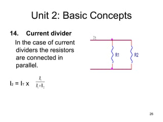
3. Kirchhoff's laws and Thevenin's theorem are presented as methods for analyzing circuits to calculate current, voltage, resistance and simplify complex networks.