
Recommended
More Related Content
Similar to EM-I PPT (1).pdf
Similar to EM-I PPT (1).pdf (20)
Recently uploaded
Recently uploaded (20)
EM-I PPT (1).pdf
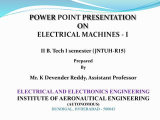
- 1. II B. Tech I semester (JNTUH-R15) Prepared By Mr. K Devender Reddy, Assistant Professor ELECTRICALAND ELECTRONICS ENGINEERING INSTITUTE OF AERONAUTICAL ENGINEERING (AUTONOMOUS) DUNDIGAL, HYDERABAD - 500043
- 3. Electromechanical systems Block structure shematics of electromechanical system Energy flow Transmission (e.g.Gears Sensor Electric motor Controller Diagnostick, supervision El. Power Supply Signal flow Power converters Power converters Electrical machine Working mechanism Sensor Controller Measured values Power converter Power circuit Signaln circuitg Gearbox Reference value Actual value Field bus El.power supply Supervisionr Diagnostics Lokal mode
- 4. Structure of the electronics converter Electro-mechanical systems Energy flow El. System A Power electronics Information system Power converter structure
- 5. What is our task? a) Introduction in basic components; how does it work ? b) Analyze components of electromechanical systems (EMS), to learn the way of working and way of control with the purpose of the energy conversion (from electrical in mechanical and vice versa) c) When one synthesize EMS, it should take a care of the energy efficiency d) Set the request on the EMS components with the purpose of realisation above mentioned request e) We will consider only such EMS where energy conversion produce the motion f) The type of the motion will be mainly linear or rotational Electro-mechanical Systems
- 6. Electro-mechanical Systems • Literature: • F. Kolonić: Textual materijals : Electromechanical System Control Course, 2012, Zagreb, Faculty of Electrical Engineering and computing, University of Zagreb. • Werner Leonhard: Control of electrical Drives, 2007 • N. Mohan: Advanced Electric Drives-Analyses, Control and Modeling using Simulink, MNPERE, Mineapolis, 2001.
- 7. Electromechanical System (EMS) is system which consists of minimum one electrical and one mechanical subsystem (systems) coupled with electromagnetic fields . With electro-magnetic field mutual interaction between those two (sub)systems has been performed. U, I M, n Electrical system Coupled Field Mechanical system Electromagnetic field represent the coupled (bracing) field. As a mutual action between magnetic field and subsystems, the energy conversion is realized from electrical to mechanical and vice-versa. Electro-mechanical Systems
- 8. Energy balance in electromechanical system Losses Energy exchange of EMS with electrical system is: WE = Wel + Wae + Wge Energy from electrical source Electrical energy transfered to magnetic field Losses in elektrical system (heat) Electrical energy in magnetic field which doesn’t belong to el.mag. field Positive if EMS accept energy from electrical system (1) Electro-mechanical Systems
- 9. WM = Wmeh + Wam + Wgm Energy from mechanical source Energy from meh. system transfered to magnetic field Losses in mechanical system (heat) Energy accumulated in moving and elastic parts of mechanical system Losses Energy which EMS exchange with mehanical system Positive if EMS accept energy from mechanical system (2) Electro-mechanical Systems Energy balance in electromechanical system
- 10. WF = Wf + Wgf Energy accumulated in magnetic field Losses in magnetic field: • eddi current • histeresys • dielectric losses (for el. field) Based on the energy maintance (conservation) low : Wf + Wgf = (WE - Wge - Wae) + (WM - Wgm - Wam) Wf + Wgf = Wel + Wmeh Total energy stored in magnetic field El.energy transfered to magnetic field Mechanical energy transfered to magnetic field Total energy entered to magnetic field (3) (4) (5) Electro-mechanical Systems Energy balance in electromechanical system
- 11. WE Wge Wae Wgf Wgm Wf Wam WM Wel Wmeh Energy conservation low: Polje sprege Električni sustav Mehanički sustav Electro-mechanical Systems Energy balance in electromechanical system
- 12. Electro-mechanical Systems - Example x x0 + - e i L R u + - k f fe D m fe x x K dt dx D dt dx m f ) ( 0 2 2 Equation of motion (Newton’s low) Electrical system voltage equation dt d N e Induced EMS (counter electromotive force, back electromotive force ) e dt di L Ri u (6) (7) (8)
- 13. EMS components description: R → parameter of coil (winding), resistance, L → parameter of coil (winding), inductance, reactance) K → parameter of spring, (coefficient of elasticity, stiffness) D →parameter of spring, (damping coefficient ) m →mass of EMS f → external force on mass (mass “m”) fe → electromagnetic force x0→ steady state position, equilibrium point of mechanical system, f =fe (forces f and fe are positive if x increse!) x → position, mechanical variable Electro-mechanical Systems
- 14. Drive machine Diesel, turbine,.. ELECTRICAL GENERATOR Electrical grid P el P Pmech Electrical to Mechanical conversion ELECTRICAL MOTOR Working machine P el P Tehnological process Mechanical to Electrical conversion Electrical grid Electro-mechanical Systems mech
- 15. The basics of electromechanical conversion 1. Voltage inducing in moving coil vertical to magnetic field 2. Positive and negative charge split up to the ends of coil; the voltage is generated! This is called as Faraday - Lentz low. E x l v B 3. Direction of induced voltage is defined with Right hand rule. If the field is going to the flat of the hand and thumb shows direction of the coil motion, positive voltage is in direction of the fingers top. (14) Electro-mechanical Systems
- 16. 4. The force applied to the coil with current which move in magnetic fields is defined by (15). 5. The direction of the electromagnetic force is defined by the Left hand rool. If the field is going to the flat of the hand and direction of the fingers are in positive voltage, then the direction of force is in direction of the thumb. I x e F F l B Obtained force on the coil doesn’t mean that mechanical work is produced!! (15) Eectro-mechanical Systems
- 17. 6. Direction of the energy conversion If the motion velocity (v) of the coil is caused by force F in magnetic field B, then induced voltage E will be according to the green arrow. If the ends of the coil are connected to the resistor R, the current will flow and as consequence electromagnetic force Fe will be generated. This force is opposite to the F force, F= - Fe R B E F Fe I v vdt F dx F dW e e meh EIdt eidt dWel El.energy in interval dt Mechanical work is negative, (direction of force and trip (distance) are not the same! (16) (17) Electro-mechanical Systems vdt F dx F dW e e meh
- 18. 6. Direction of energy conversion (continuing) Negative sign of the work (17) means that mechanical system doesn’t receive energy, i.e. It must generate energy (i.e.work) to enable the moving the coil with the same speed during the time dt. Electrical energy is produced and mechanical energy is consumed. This example illustrates principal of the generator work! Electro-mechanical Systems
- 19. B E Fe I v U + vdt F dx F dW e e meh EIdt eidt dWel 7. Direction of energy conversion Mechanical energy is obtained, and electrical energy is consumed. This example illustrate electrical to mechanical conversion, i.e. the principal of the motor work. (20) (21) Electro-mechanical Systems
- 20. 8. Direction of energy conversion U is electrical system’s voltage, E is induced ems according to (14). Until U > E, current has direction from U to E, motor work, force Fe act in the same direction as distance increment vdt When U = E, current is zero, there is no conversion. When U < E, current change the sign, it is generator work now; direction of force Fe is opposite to the direction of distance increment vdt. R is the resistance of whole circuit. R E U I (21) Electro-mechanical Systems
- 21. • Magnetic field, • Coils, located in magnetic field, • Relative motion between the coils against the magnetic field, • Coils connection to the external electric circuit, • Transfer of force (torque) to the working mechanism. Electro-mechanical Systems
- 22. 2. Limitation in expression E = B l v: • The amount of induction B is limited by ferromagnetic materials Bz ≈ (1,7 - 2) T • The length of the coil(l) is limited by mechanical reasons (problems of embedding) • The maximal speed is limited by construction strength, friction losses and heating caused by friction 1. Magnetic field : • It can be realized with electromagnets or with permanent magnets • Permanent magnets arewith limited dimensions, they are used for electrical machines with limited dimensions and power ratings . Electro-mechanical Systems
- 23. Magnetic field with permanent magnets Magnetic circuit realized with permanent magnet, soft magnetic material (iron) B – induction in air gap Φ – magnetic field in core (constant) N S N S permanent magnet soft magnetic materijal (iron) B v coil δ Φ Magnetic field of permanent magnet Electro-mechanical Systems
- 24. Magnetic fields realized by DC current This is principle of electromagnet. • i0 is exciting current which produce magnetic field. • There is no limitation on magnet dimension and magnetic circuits. • Changing R in exciting coil, the amount of current doesn’t change, as well as magnetic field of the core. + - R i0 N S v 1 B 2 Soft magnetic material (iron) vodič Φ δ V V 1' 2' Constant current in industrial application realized with power electronics components(controlled constant current source) Electro-mechanical systems
- 25. Depending of what and when calculate, in electromagnetic and in electromechanic energy conversion, magnetic field can be presented in a three different way: - induction B [Wb/m2] , [ T ] (Tesla) ili [Vs/m2] - field Φ [Wb] (Weber) ili [Vs] - coupled field Ψ Total number of magnetic lines define magnetic field S Bd S Electro-mechanical sistems
- 26. 4. Vodiči smješteni u magnetskom polju Axial conductors in slots of stator conductors design (windings), b); slotting design c) Important: System of rings (or slices of collectors) and brushes, enable connection of rotary elements with stationary world, a) b) c) a) Electromechanical system
- 27. 5. Relative motion of coil against the lines of magnetic fields Translational (linear) a) and rotation motion b) of coil in air gap. Principle of translational and rotational motion of electrical machine) Important: air gap must be very narrow! With equal magnetic field, narrower air gap results with higher induction in the air gap (minor loss of magnetic lines) a) b) Elektromehanički sustavi
- 28. Example: Force on conductor Simplified “magnetic lift” is presented on the picture, see figure. Distance between vertical rigid rods is 0,5 m, and mass of load for hoisting is 2 kg. Mass of coil is 1kg. Influence of friction force can be neglected. a) Calculate the current thru coil in order to lift-up load a) and hang the load in desired position, b). b) If the current is 50 A, find the direction of force and motion. Calculate the acceleration of the lift I B = 1,5 T = 0,5 m vertical conductive rod coil F Fg Electro-mechanical systems
- 29. SOLUTION: a) For zero motion of coil and load, electromagnetic force on coil and load must be equal to gravitation force, F = F g B I l= (m v + m t) 9,81 If the coil and load must be moved up (hoist), electromagnetic force on coil must be higher than the gravitation force: F > F g I > 39,24 A b) Electromagnetic force with current of 50A iz: F = B I l = 1,5∙50∙0,5 = 37,5 N gravitation force: F g = mg = (2+1)∙9,81= 29,43 N Acceleration force: F u = F – F g = 37,5 – 29,43 = 8,07 N Electro-mechanical systems
- 30. Electro-mechanical systems REMINDER: Basics of electromechanical systems 1. The force on the moving charge in magnetic field of induction B: +Q B v Fem Q – amount of charge v - charge velocity B – magnetic induction, magnetic field density • Direction of force F (Fem) is defined by right screw rule. Force act in direction of the screw advancing B v F x Q (13)
- 31. Electro-mechanical Systems Energy which EMS exchange in time dt with ELECTRICAL system is: uidt dWE eidt Lidi dt Ri dWE 2 eidt dWel fdx dWM dx f dx x x K dt dx D dx dt dx m dW e M ) ( 0 2 2 2 dx f dW e meh Losses accumulated in mass and spring Friction losses (spring fastened on the wall) Important: Let we take that fe act in direction of dx shift ing. In that case energy is transferred from coupled field in mechanical system system, ie. we are talking about electrical to mechanical energy conversion!!! (9) (10)
- 32. Electro-mechanical systems U promatranom EMS-u polje sprege je MAGNETSKO polje, pa se za akumuliranu energiju polja sprege koristi pojam MAGNETSKA energija i označava se s Wm. Na osnovi prethodnih razmatranja, za prirast akumulirane magnetske energije dWm,dobije se dx f eidt dW e m meh el m dW dW dW Jednadžba se može poopćiti na EMS s proizvoljnim brojem električnih i mehaničkih ulaza i proizvoljnim brojem sprega. (11) (12)
- 35. Maxwell’s Cork screw Rule : Hold the cork screw in yr right hand and rotate it in clockwise in such a way that it advances in the direction of current. Then the direction in which the hand rotates will be the direction of magnetic lines of force .
- 36. Fleming’s left hand rule
- 37. Fleming’s left hand rule Used to determine the direction of force acting on a current carrying conductor placed in a magnetic field . The middle finger , the fore finger and thumb of the left hand are kept at right angles to one another . The middle finger represent the direction of current The fore finger represent the direction of magnetic field The thumb will indicate the direction of force acting on the conductor . This rule is used in motors.
- 38. Fleming’s Right hand rule
- 39. Fleming’s Right hand rule Used to determine the direction of emf induced in a conductor The middle finger , the fore finger and thumb of the left hand are kept at right angles to one another. The fore finger represent the direction of magnetic field The thumb represent the direction of motion of the conductor The middle finger will indicate the direction of the inducted e.m.f . This rule is used in DC Generators
- 40. Len’s Law The direction of induced emf is given by Lenz’s law According to this law, the induced emf will be acting in such a way so as to oppose the very cause of production of it . e = -N (dØ/dt) volts
- 41. DC Generator Mechanical energy is converted to electrical energy Three requirements are essential 1. Conductors 2. Magnetic field 3. Mechanical energy
- 42. Working principle A generator works on the principles of Faraday’s law of electromagnetic induction Whenever a conductor is moved in the magnetic field , an e.m.f is induced and the magnitude of the induced e.m.f is directly proportional to the rate of change of flux linkage. This e.m.f causes a current flow if the conductor circuit is closed .
- 44. Sectional view of a DC machine
- 45. Construction of DC Generator Field system Armature core Armature winding Commutator Brushes
- 46. Field winding
- 47. Rotor and rotor winding
- 48. Working principle of DC motor
- 49. Working principle of DC motor
- 50. Force in DC motor
- 51. Armature winding There are 2 types of winding Lap and Wave winding Lap winding A = P The armature windings are divided into no. of sections equal to the no of poles Wave winding A = 2 It is used in low current output and high voltage. 2 brushes
- 52. Field system It is for uniform magnetic field within which the armature rotates. Electromagnets are preferred in comparison with permanent magnets They are cheap , smaller in size , produce greater magnetic effect and Field strength can be varied
- 53. Field system consists of the following parts Yoke Pole cores Pole shoes Field coils
- 54. Armature core The armature core is cylindrical High permeability silicon steel stampings Impregnated Lamination is to reduce the eddy current loss
- 55. Commutator Connect with external circuit Converts ac into unidirectional current Cylindrical in shape Made of wedge shaped copper segments Segments are insulated from each other Each commutator segment is connected to armature conductors by means of a cu strip called riser. No of segments equal to no of coils
- 56. Carbon brush Carbon brushes are used in DC machines because they are soft materials It does not generate spikes when they contact commutator To deliver the current thro armature Carbon is used for brushes because it has negative temperature coefficient of resistance Self lubricating , takes its shape , improving area of contact
- 57. Brush rock and holder
- 58. Carbon brush Brush leads (pig tails) Brush rocker ( brush gear ) Front end cover Rear end cover Cooling fan Bearing Terminal box
- 59. EMF equation Let, Ø= flux per pole in weber Z = Total number of conductor P = Number of poles A = Number of parallel paths N =armature speed in rpm Eg = emf generated in any on of the parallel path
- 60. EMF equation Flux cut by 1 conductor in 1 revolution = P * φ Flux cut by 1 conductor in 60 sec = P φ N /60 Avg emf generated in 1 conductor = PφN/60 Number of conductors in each parallel path = Z /A Eg = PφNZ/60A
- 61. UNIT-III TYPES OF DC GENERATORS
- 62. Types of DC Generator DC generators are generally classified according to their method of excitation Separately excited DC generator Self excited D C generator
- 63. Further classification of DC Generator Series wound generator Shunt wound generator Compound wound generator Short shunt & Long shunt Cumulatively compound Differentially compound
- 64. For appreciable generation of emf, the field resistance must be always less certain resistance, that resistance is called as the critical resistance of the machine . Critical field resistance
- 65. General terms used in Armature reaction Magnetic neutral axis : It is perpendicular to the lines of force between the two opposite adjacent poles. Leading pole Tip (LPT) : It is the end of the pole which first comes in contact with the armature. Trailing pole tip : It is the end of the pole which comes in contact later with the armature.
- 66. Armature Reaction Interaction of Main field flux with Armature field flux
- 67. Effects of Armature Reaction It decreases the efficiency of the machine It produces sparking at the brushes It produces a demagnetizing effect on the main poles It reduces the e.m.f induced Self excited generators some times fail to build up e.m.f
- 68. Armature reaction remedies 1.Brushes must be shifted to the new position of the MNA 2.Extra turns in the field winding 3.Slots are made on the tips to increase the reluctance 4. The laminated cores of the shoe are staggered 5. In big machines the compensating winding at pole shoes produces a flux which just opposes the armature mmf flux automatically.
- 69. Commutation The change in direction of current takes place when the conductors are along the brush axis . During this reverse process brushes short circuit that coil and undergone commutation Due to this sparking is produced and the brushes will be damaged and also causes voltage dropping.
- 70. DC Generator Characteristics In general, three characteristics specify the steady-state performance of a DC generators: 1. Open-circuit characteristics: generated voltage versus field current at constant speed. 2. External characteristic: terminal voltage versus load current at constant speed. 3. Load characteristic: terminal voltage versus field current at constant armature current and speed.
- 71. DC Generator Characteristics a a m f a a a t R I drop reaction Armature I f R I E V , Open-circuit and load characteristics The terminal voltage of a dc generator is given by
- 72. DC Generator Characteristics 100 t t a V V E regulation Voltage It can be seen from the external characteristics that the terminal voltage falls slightly as the load current increases. Voltage regulation is defined as the percentage change in terminal voltage when full load is removed, so that from the external characteristics, External characteristics
- 73. Self-Excited DC Shunt Generator Schematic diagram of connection Open-circuit characteristic Maximum permissible value of the field resistance if the terminal voltage has to build up.
- 74. Losses in DC Generators 1. Copper losses or variable losses 2. Stray losses or constant losses Stray losses : consist of (a) iron losses or core losses and (b) windage and friction losses . Iron losses : occurs in the core of the machine due to change of magnetic flux in the core . Consist of hysteresis loss and eddy current loss. Hysteresis loss depends upon the frequency , Flux density , volume and type of the core .
- 75. Losses Hysteresis loss depends upon the frequency , Flux density , volume and type of the core . Eddy current losses : directly proportional to the flux density , frequency , thickness of the lamination . Windage and friction losses are constant due to the opposition of wind and friction .
- 76. Parallel Operation of DC Generators:
- 77. The positive terminals of the generators are .connected to the +ve side of bus-barsand negative terminals to the negative side of bus- bars The prime mover of generator 2 is brought up to the rated speed. Now switch S4 in the field circuit of the generator 2 is closed. Next circuit breaker CB-2 is closed and the excitation of generator 2 is adjusted till it generates voltage equal to the bus-bars voltage. This is indicated by voltmeter V2. Now the generator 2 is ready to be paralleled with generator 1. The main switch S3 is closed, thus putting generator 2 in parallel with 50
- 78. I1 = E1 −V an d I2 = E2 −V R2 R1 Load Sharing: The load sharing between shunt generators in parallel can be easily regulated because of their drooping characteristics. The load may be shifted from one generator to another merely by adjusting the field excitation. Let us discuss the load sharing of two generators which have unequal no-load voltages. Let E1, E2 = no-load voltages of the two generators R1, R2 = their armature resistances V = common terminal voltage (Bus-bars voltage). Then Thus current output of the generators depends upon the values of E1 and E2. These values may be changed by field rheostats. The common terminal voltage (or bus- bars voltage) will depend upon (i) the emfs of individual generators and (ii) the total load current supplied. It is generally desired to keep the busbars voltage constant. This can be achieved by adjusting the field excitations of the generators operating in parallel.
- 79. Shunt Generators: a. in electro plating b. for battery recharging c. as exciters for AC generators. Applications Series Generators : A. As boosters B. As lighting arc lamps
- 80. UNIT-IV DC MOTORS & SPEED CONTROL METHODS
- 81. Contents Overview of Direct Current Machines Construction Principle of Operation Types of DC Motor Power Flow Diagram Speed Control Starters
- 82. DC motor principles DC motors consist of rotor-mounted windings (armature) and stationary windings (field poles). In all DC motors, except permanent magnet motors, current must be conducted to the armature windings by passing current through carbon brushes that slide over a set of copper surfaces called a commutator, which is mounted on the rotor. Parts of an electric motor The commutator bars are soldered to armature coils. The brush/commutator combination makes a sliding switch that energizes particular portions of the armature, based on the position of the rotor. This process creates north and south magnetic poles on the rotor that are attracted to or repelled by north and south poles on the stator, which are formed by passing direct current through the field windings. It's this magnetic attraction and repulsion that causes the rotor to rotate.
- 83. The Advantages The greatest advantage of DC motors may be speed control. Since speed is directly proportional to armature voltage and inversely proportional to the magnetic flux produced by the poles, adjusting the armature voltage and/or the field current will change the rotor speed. Today, adjustable frequency drives can provide precise speed control for AC motors, but they do so at the expense of power quality, as the solid-state switching devices in the drives produce a rich harmonic spectrum. The DC motor has no adverse effects on power quality.
- 84. The drawbacks Power supply, initial cost, and maintenance requirements are the negatives associated with DC motors Rectification must be provided for any DC motors supplied from the grid. It can also cause power quality problems. The construction of a DC motor is considerably more complicated and expensive than that of an AC motor, primarily due to the commutator, brushes, and armature windings. An induction motor requires no commutator or brushes, and most use cast squirrel-cage rotor bars instead of true windings — two huge simplifications.
- 85. Major types of dc motors Self excited dc motor Series dc motor Shunt dc motor Compound dc motor Separately excited dc motor Permanent magnet dc motor
- 86. Series motors Series motors connect the field windings in series with the armature. Series motors lack good speed regulation, but are well-suited for high- torque loads like power tools and automobile starters because of their high torque production and compact size. Ea Rf M VT (dc supply) Ra ia ) ( f a a a T R R i E V L a i i note : a a I K K E 2 1
- 87. Series Motor Power Flow Diagram P Pout Pin= VTiL Pca=ia 2Ra Pcf=ia 2Rf Pm P is normally given Pin = Pout + total losses Where, Pca =armature copper loss Pcf =field copper loss P=stray, mech etc in out m m o o P P Efficiency N P torque mechanical for N P torque load output for N P , 2 60 , 2 60 , / 2 60 Pm= Ea ia
- 88. Series Motor (cont) Example 1: A dc machine in Figure 1 is consumed a 6.5kW when the 12.5 A of armature current is passing thru the armature and field resistance of 3.3 and 2.0 respectively. Assume stray losses of 1.2kW. Calculate a) terminal voltage, VT b) back emf, Ea c) net torque if the speed is at 3560rpm d) efficiency of the machine [520V, 453.75V, 12N-m, 68.8%] Ea Rf M VT (dc supply) Ra ia Figure 1
- 89. Series Motor (cont) Example 2: A 600V 150-hp dc machine in Figure 2 operates at its full rated load at 600rpm. The armature and field resistance are 0.12 and 0.04 respectively. The machine draws 200A at full load. Assume stray losses 1700W. Determine a) the armature back emf at full load, Ea b) developed/mechanical power and developed/mechanical torque c) assume that a change in load results in the line current dropping to 150A. Find the new speed in rpm and new developed torque. {Hint: Ea=K1K2ia} Ea Rf M VT (dc supply) Ra ia Figure 2 [568V, 113.6kW, 1808Nm, 811.27rpm, 1017Nm]
- 90. Shunt motors Shunt motors use high-resistance field windings connected in parallel with the armature. Varying the field resistance changes the motor speed. Shunt motors are prone to armature reaction, a distortion and weakening of the flux generated by the poles that results in commutation problems evidenced by sparking at the brushes. Installing additional poles, called interpoles, on the stator between the main poles wired in series with the armature reduces armature reaction. Ea VT (dc supply) Ra ia if Rf M iL ) ( a a a T R i E V f f T f a L R i V i i i note :
- 91. Shunt Motor (power flow diagram) P Pout Pin=VTiL Pca=ia 2Ra Pcf=if 2Rf Pm P is normally given Pin = Pout + total losses Where, Pca =armature copper loss Pcf =field copper loss P=stray, mech etc in out m m o o P P Efficiency N P torque mechanical for N P torque load output for N P , 2 60 , 2 60 , / 2 60 Pm= Ea ia
- 92. Shunt Motor Example : A voltage of 230V is applied to armature of a machines results in a full load armature currents of 205A. Assume that armature resistance is 0.2. Find the back emf, net power and torque by assuming the rotational losses are 1445W at full load speed of 1750rpm. [Ans: 189V, 37.3kW, 203.5Nm]
- 93. Compound motors the concept of the series and shunt designs are combined. Ea VT (dc supply) Ra ia if Rf1 M iL Rf2 ) ( 2 f a a a T R R i E V 1 : f f T f a L R i V i i i note
- 94. Compound motor (power flow diagram) P is normally given Pin = Pout + total losses Where, Pca =armature copper loss Pcf =field copper loss P=stray, mech etc in out m m o o P P Efficiency N P torque mechanical for N P torque load output for N P , 2 60 , 2 60 , / 2 60 Pm= Ea ia P Pout Pin=VTiL Pca=ia 2Ra Pcf1=if 2Rf1 Pm Pcf2=ia 2Rf2
- 95. Separately Excited Motor There is no direct connection between the armature and field winding resistance DC field current is supplied by an independent source (such as battery or another generator or prime mover called an exciter)
- 96. Separately Excited Motor (Cont) n K n i K C pnZ E f f f a 60 2 f f f R i V a a a T R i E V Where p= no of pole pair n= speed (rpm) Z=no of conductor =Flux per pole (Wb) C= no of current/parallel path =2p (lap winding) =2 (wave winding) KVL: Circuit analysis: L a i i note : Ea Ra La ia M Rf VT Vf Lf If
- 97. Permanent Magnet motors PMDC is a dc motor whose poles are made of permanent magnets. Do not require external field circuit, no copper losses No field winding, size smaller than other types dc motors Disadvantage: cannot produce high flux density, lower induce voltage
- 98. Torque The turning or twisting force about an axis is called torque . P = T * 2 πN/ 60 Eb Ia = Ta * 2 πN/ 60 T ∞ φ I a Ta ∞ I2a
- 99. Characteristic of DC motors T/ Ia characteristic N/ I a characteristic N/T characteristic
- 100. Speed Control in DC Motors Shunt motor: Electromagnetic torque is Te=Ka fd Ia, and the conductor emf is Ea=Vt - RaIa. For armature voltage control: Ra and If are constant For field control: Ra and Vt are constant For armature resistance control: Vt and If are constant 2 2 1 e t m T K V K 3 2 e f f a f f t m T I K R I K V 1 2 d a a e d a t m a d a e t m d a K R T K V R K T V K f f f f 4 2 e d a adj a d a t m T K R R K V f f
- 101. Speed Control in Shunt DC Motors Armature Voltage Control: Ra and If are kept constant and the armature terminal voltage is varied to change the motor speed. For constant load torque, such as applied by an elevator or hoist crane load, the speed will change linearly with Vt. In an actual application, when the speed is changed by varying the terminal voltage, the armature current is kept constant. This method can also be applied to series motor. . const is ; K K ; K K T K V K d d a d a e t m f f f 2 2 1 2 1 1 1
- 102. Field Control: Ra and Vt are kept constant, field rheostat is varied to change the field current. For no-load condition, Te=0. So, no-load speed varies inversely with the field current. Speed control from zero to base speed is usually obtained by armature voltage control. Speed control beyond the base speed is obtained by decreasing the field current. If armature current is not to exceed its rated value (heating limit), speed control beyond the base speed is restricted to constant power, known as constant power application. Speed Control in Shunt DC Motors m m a a e m e a a a t . const I E T T I E const I V P e f f a f f t m T I K R I K V 2
- 103. Armature Resistance Control: Vt and If are kept constant at their rated value, armature resistance is varied. The value of Radj can be adjusted to obtain various speed such that the armature current Ia (hence torque, Te=KafdIa) remains constant. Armature resistance control is simple to implement. However, this method is less efficient because of loss in Radj. This resistance should also been designed to carry armature current. It is therefore more expensive than the rheostat used in the field control method. Speed Control in Shunt DC Motors e e d a adj a d a t m T K K T K R R K V 6 5 2 f f
- 104. Armature Voltage Control: A variable dc voltage can be applied to a series motor to control its speed. A variable dc voltage can be obtained from a power electronic converter. Torque in a series motor can be expressed as Speed Control in Series DC Motors s a e t s a s a s a e t m s a m s a t s a a s a a d a e K K T V K K R R K K T V , or R R K K V K K I K K I K T f 2 2 2 s a m s a t a s a a m a s a s a a m d a s a a a t a s d R R K K V I R R I I K K R R I K R R I E V I K f f
- 105. Field Control: Control of field flux in a sries motor is achieved by using a diverter resistance. The developed torque can be expressed as. Speed Control in Series DC Motors d s d s a a a d s d s a a d a e R R R and K K K , where I K I R R R K K I K T f 2 2 a s m t a a a s m a a s m a s a a a s a m d a a a a d s d s a t R R K V I , or I R R K I R R I K K R I R I K R I I R R R R E V f
- 106. Speed Control in Series DC Motors 2 a s m t e R R K V K T
- 107. Armature Resistance Control: Torque in this case can be expressed as Rae is an external resistance connected in series with the armature. For a given supply voltage and a constant developed torque, the term (Ra+Rae+Rs+Km) should remain constant. Therefore, an increase in Rae must be accompanied by a corresponding decrease in m. Speed Control in Series DC Motors K R R R KT V , or V T K K R R R , or T KV K R R R s adj a e t m t e m s adj a e t m s adj a 2 2 2 2 m s adj a t e K R R R KV T
- 108. FACTORS AFFECTING THE PERFORMANCE OF DC MACHINE There are two factors affecting the performance of dc machine Armature reaction Armature inductance
- 109. Armature Reaction Definition of armature reaction: It is the term used to describe the effects of the armature mmf on the operation of a dc machine as a "generator" no matter whether it is a generator or motor. It effects both the flux distribution and the flux magnitude in the machine. The distortion of the flux in a machine is called armature reaction Two effects of armature reaction: Neutral Plane Shift Flux Weakening
- 110. Armature Reaction Effect on flux distribution: Neutral plane shift When current is flowing in the field winding, hence a flux is produced across the machine which flows from the North pole to the South pole. Initially the pole flux is uniformly distributed and the magnetic neutral plane is vertical
- 111. Armature Reaction Effect on flux distribution: Neutral plane shift effect by the air gap on the flux field causes the distribution of flux is no longer uniform across the rotor. There are two points on the periphery of the rotor where B= 0.
- 112. Armature Reaction Effect on flux distribution: Neutral plane shift when a load connected to the machines a resulting magnetic field produced in the armature If the armature is rotated at a speed by an external torque each armature coil experiences a change in flux ft as it rotates. A voltage is generated across the terminals of each winding according to the equation e = ft
- 113. Armature Reaction Effect on flux distribution: Neutral plane shift Both rotor and pole fluxes (flux produced by the field winding and the flux produced by the armature winding) are added and subtracted together accordingly The fields interact to produce a different flux distribution in the rotor. Thus, the flux on the middle line, between the two field poles, is no longer zero.
- 114. Armature Reaction Effect on flux distribution: Neutral plane shift The combined flux in the machine has the effect of strengthening or weakening the flux in the pole. Neutral axis is therefore shifted in the direction of motion. The result is current flow circulating between the shorted segments and large sparks at the brushes. The ending result is arcing and sparking at the brushes. Solution to this problem: placing an additional poles on the neutral axis or mid-point that will produce flux density component, which counter-acts that produced by the armature.
- 115. Armature Reaction Effect on flux magnitude: Flux Weakening Most machine operate at saturation point When the armature reaction happen, at location pole surface: The add of rotor mmf to pole mmf only make a small increase in flux The subtract of rotor mmf from pole mmf make a large decrease in flux. The result is the total average flux under entire pole face is decreased. This is called Flux Weakening fd –flux decrease under subtracting section of poles
- 116. Armature Inductance When rotor turns, thus we have inductance value, e1 = L(di/dt). Let say current ia1. That means, we have ability to store energy If the machine is turn ‘off’, thus, e1 will decreased. This will affect the current as well. Say ia2. When the machine is turn ‘on’ again, it will produce e2 while e1 is still inside. The current now is reversed direction from previous (decreasing) current. Thus, it will cause sparking resulting the same aching problem caused by neutral plane shift.
- 117. Starters for DC motors Needed to limit the starting current . 1. Two point starter 2. Three point starter 3. Four point starter
- 118. 3 Point Starter:
- 119. To start with, the d.c. supply is switched on with handle in the OFF position. The handle is now moved clockwise to the first stud. As soon as it comes in contact with the first stud, the shunt field winding is directly connected across the supply, while the whole starting resistance is inserted in series with the armature circuit. As the handle is gradually moved over to the final stud, the starting resistance is cut out of the armature circuit in steps. The handle is now held magnetically by the no-volt release coil which is energized by shunt field current.
- 120. If the supply voltage is suddenly interrupted or if the field excitation is accidentally cut, the no-volt release coil is demagnetized and the handle goes back to the OFF position under the pull of the spring. If no-volt release coil were not used, then in case of failure of supply, the handle would remain on the final stud. If then supply is restored, the motor will be directly connected across the supply, resulting in an excessive armature current. If the motor is over-loaded (or a fault occurs), it will draw excessive current from the supply. This current will increase the ampere-turns of the over-load release coil and pull the armature C, thus short-circuiting the no- volt release coil. The no-volt coil is demagnetized and the handle is pulled to the OFF position by the spring. Thus, the motor is automatically disconnected from the supply.
- 121. Drawback: In a three-point starter, the no-volt release coil is connected in series with the shunt field circuit so that it carries the shunt field current. While exercising speed control through field regulator, the field current may be weakened to such an extent that the no-volt release coil may not be able to keep the starter arm in the ON position. This may disconnect the motor from the supply when it is not desired. This drawback is overcome in the four point
- 122. 4-Point Starter:
- 123. In a four-point starter, the no-volt release coil is connected directly across the supply line through a protective resistance R. Figure above shows the schematic diagram of a 4-point starter for a shunt motor (over-load release coil omitted for clarity of the figure). Now the no-volt release coil circuit is independent of the shunt field circuit. Therefore, proper speed control can be exercised without affecting the operation of no- volt release coil. Note that the only difference between a three-point starter and a four-point starter is the manner in which no-volt release coil is connected. However, the working of the two starters is the same. It may be noted that the three- point starter also provides protection against an open- field circuit. This protection is not provided by the four-point
- 124. Applications: Shunt Motor: Blowers and fans Centrifugal and reciprocating pumps Lathe machines Machine tools Milling machines Drilling machines
- 125. Applications: Series Motor: Cranes Hoists , Elevators Trolleys Conveyors Electric locomotives
- 126. Applications: Cumulative compound Motor: Rolling mills Punches Shears Heavy planers Elevators
- 127. UNIT-V TESTING OF DC MACHINES
- 128. Magnetic losses Hysteresis losses : The property of a magnetic material to retain a part of the magnetizing achieved by it, one removal of the driving force is called hysteresis. The power required to overcome this hysteresis effect is called hysteresis loss. It is denoted by Wn. Wh f Bm 1.6 Wh = 7 Bm 1.6 f Eddy current losses : When the iron part (rotor) rotates in the stationary field, there is an induced emf in the iron part also apart from the emf induced in the copper windings. This emf is called eddy emf. The iron part provides a closed path for the eddy emf to circulate a current. This current is called eddy current.
- 129. Mechanical losses Friction losses : The rotation of the armature inside the bearings causes friction to be developed. In order to over come this, the prime more has to supply more power. Windage losses : An extra mounting on the shaft of the armature such as fan to provide air for cooling purposes causes an extra burden on the prime motor. The extra power required to drive the fan is termed as windage loss. (constant)
- 130. Efficiency Input Power Losses Input Power Losses Input Power Input Power Output Power 1 The losses are made up of rotational losses (3-15%), armature circuit copper losses (3-6%), and shunt field copper loss (1-5%). The voltage drop between the brush and commutator is 2V and the brush contact loss is therefore calculated as 2Ia.
- 131. CONTENTS 1. Testing method of dc m/c. 2. simple/direct test . (a) Explanation,(b) Numerical (C) Disadvantage . 3 .Swinburne’s test. 4.Hopkinsion’s test
- 132. TESTING OF DC MACHINE Machines are tested for finding out losses, efficiency and temperature rise. For small m/c we used DIRECT LOADING test and for large shunt m/c, INDIRECT MET- HOD are used.
- 133. TESTING METHOD ARE Simple / Direct test. Swinburne’s / Indirect Method test. Hopkinson’s / Regenerative / Back - to - Back / Heat –run test.
- 134. Simple / Direct test This method is suitable only for SMALL DC m/c. In direct, method the DC m/c is subjected to rated load and the entire o/p power is wasted. The ratio of o/p power to i/p power gives the efficiency of DC m/c.
- 135. EFFICIENCY MOTOR Motor o/p={ω(s1-s2)r× 9. 81} Motor i/p= VtI. ή(motor)={o/p}/{i/p}. = [{ω(s1-s2)r× 9. 81}×100]/VtI where; s1&s2 are the tension on the belt. ω=2πn(motor speed in rad/sec r=radius of pulley in meters(=1/2 out side pulley dia+1/2 belt thickness) Vt=terminal voltage & I=line current.
- 136. DISADVANTAGES The spring balance readings are not steady. Friction torque does not const. At a particular setting of handwheels H1&H2
- 137. INDIRECT METHOD In this method ,no load m/c losses are first measured by a suitable test and then additional losses on load are determined from the m/c data ,in order to calculate the m/c efficiency . The simplest method of measuring the no load m/c losses is by SWINBURNE’S METHOD.
- 138. SWINBURNE’S METHOD As this is no load test ,it can’t be performed on a dc series motor In this method, the m/c whether it is a MOTOR or GENERATOR, is run as a no load shunt motor at rated speed
- 139. If Ia0 and If are the no load armature and field current respectively .Then power absorbed by the armature (=Vt×Iao) is equal to the no load rotational loss W0 plus a small amount armature circuit loss Ia0^2 ×ra. No load rotational loss W0=Vt×Iao- Ia0^2 ×ra. Here armature circuit resistance ra includes the brush contact resistance also. Shunt field loss=Vt×If.
- 140. Let IL be the load current at which m/c efficiency is required. Generator efficiency Generator o/p=Vt×IL Armature current Ia=IL+If Armature circuit loss= Ia^2×ra ra=armature circuit resistance when hot. Total loss=W0+ Ia^2×ra+Vt×If ή(Generator)=[1-{(W0+ Ia^2×ra+Vt×If)}/{(Vt×IL+ W0+ Ia^2×ra+Vt×If)}]
- 141. Motor efficiency When m/c is working as a motor then Ia=IL-If Motor i/p=Vt×IL ή(motor efficiency)=[1- {(W0+Ia^2×ra+If×Vt)}/{(Vt×IL)}]
- 142. ADVANTAGES Low power is required for testing even large m/c, since only no load losses are to be supplied from the main. It is convenient and economical. The efficiency can be calculated at any load because constant losses are known.
- 143. DISADVANTAGES As the test is on no load, it doesn’t indicate whether the commutation on full load is satisfactory and whether the temperature rise would be within specified limit. THIS TEST CAN’T BE APPLIED FOR A SERIES MOTOR because speed of series motor is very high at no load ,it is not possible to run series motor on no load. Note:-In comparison to other the armature cu losses is so small that it may be neglected & constant loss may be take equal to no load i/p
- 144. Regenerative/Hopkinson’s method. In this method ,two identical d.c m/c are coupled ,both mechanically & electrically and are tested simultaneously. One of the m/c made to run as a MOTOR and it derives the other m/c as GENERATOR For this test m/c 1 is as a dc shunt motor by a starter & brought upto rated speed with switch S open .Bothe the m/c run at same speed ,because these are MECHANICALLY coupled .
- 145. CIRCUIT:
- 146. TO PERFORM THE TEST FOLLOWING PROCEDURE IS ADOPTED: M/c 1(motor) is started through starter & its field rheostat is adjusted so that it runs at normal speed. The m/c 1(Motor) will drive m/c 2(Generator).The switch S is initially kept open. The excitation of m/c 2 is gradually increased ( by decreasing the field circuit resistance).till the volt metre 1 reads ZERO.Then switch S is closed.
- 147. M/c 2 is now floating neither taking any current from the supply nor delivering any current .Any desired load can be put on the set by adjusting the shunt field regulators.The m/c with lower excitation will act as a MOTOR and other m/c will act as a GENERATOR. Let V=supply voltage I2=Armature current of m/c 2(Generator) I1= Armature current of m/c 1(motor) . If2=Field current of m/c 2(Generator). If1=Field current of m/c 1(Motor). Ra=Armature resistance of each m/c
- 148. Motor i/p power =V(I+I2)=V×I1 Generator o/p power=V×I2. ............(1) If both the m/c have same efficiency ή,then o/p of motor =ή×i/p =ήV(I+I2)= V×I1 =Generator i/p . o/p of Generator =ή×i/p . =ή×ήV×I1=ή^2V(I1)............(2) From equ (1) & (2). ή^2V(I1)=V×I2. sqrt{(I2/(I1)}
- 149. EFFICIENCY Armature circuit loss in Generator =I2^2×ra . Armature circuit loss in Motor=I1^2×ra . Power drawn from supply= V×I. No load rotational loss in two m/c=W0= V×I-ra(I1^2+I2^2) . No load rotational loss for each m/c=W0/2 . Generator o/p= I2^2×ra. Generator loss=Wg=(W0/2)+V×If2+ I2^2×ra. ή(g)=[1-(Wg)/(V×I2+Wg)]
- 150. Motor i/p=V(I1+If1) Total motor losses Wm=(W0/2)+ V×If1 +I1^2×ra . ή( Motor)=[1-(Wm)/V(I1+If2)]
- 151. ADVANTAGE Total power taken from the supply is very low. Therefore this method is very economical. The temperature rise and the commutation condition can be checked under rated load condition. Large m/c can be tested at rated load without consuming much power from the supply. Efficiency at different load can be determine.
- 152. DISADVANTAGES The main disadvantage of this method is the necessity two practically identical m/c to be available