1. This watermark does not appear in the registered version - http://www.clicktoconvert.com
Page |1
UNIT I
Lesson – 1
ELECTROMAGNETIC THEORY AND OPTICAL PHYSICS
1.0 Aims and Objectives
1.1 (a) Electric potential at a point due to an electric dipole:
(b) Electric field at any point due to an electric dipole
1.2 Dielectric polarization
1.3 Relative permitivity (dielectric constant) and displacement vector
1.4 External field of a dielectric medium
1.5 Relation between electric displacement, electric field and polarisation (D, E and P)
1.6 Molecular field in a dielectric (Clausius-Mossotti relation)
1.7 Polarizaiton of polar-molecules (Debye’s formula)
1.8 Electrostatic energy and energy density in free space and in dielectric
1.9 Let us sum up
1.10 Check your progress
1.11 Lesson-end activities
1.12 Points for discussion
1.13 References
1.0 Aims and Objectives
This lesson deals with potential and fields due to electric dipole. The relation
between electric susceptibility, polarization, displacement will be obtained. The molecular
field, derivation of claussion mossotti relation for non-polar molecules, Debge formula for
polar molecules are explained in detail. The derivation of electrostatic energy and energy
density who has has discussed.
1.1(a) ELECTRIC POTENTIAL AT A POINT DUE TO AN ELETRIC DIPOLE:
Two charges –q at A and +q at B separated by a small distance 2d constitutes an electric
dipole and its dipole moment is p (Fig 1.1a).
Let r1 and r2 be the distances of the point P from +q and –q charges respectively. Let P
be the point at a distance r from the midpoint of the dipole O and q be the angle between PO
and the axis of the dipole OB.
2. This watermark does not appear in the registered version - http://www.clicktoconvert.com
Page |2
Fig 1.1(a)
1 q
Potential at P due to charge (+q) = 4pe 0 r1
1 æ q ö
Potential at P due to charge (-q) = ç-
ç r ÷
÷
4pe 0 è 2 ø
1 q 1 q
Total Potential at P due to dipole is, V = -
4pe 0 r1 4pe 0 r2
q æ1 1ö
V= ç - ÷
çr r ÷ (1)
4pe 0 è 1 2 ø
Applying cosine law,
2
r1 = r 2 + d 2 - 2rd cos q
2 æ cos q d 2 ö
r1 = r 2 ç1 - 2d
ç + 2 ÷
÷
è r r ø
Since d is very smaller than r, d2 /r2 can be neglected.
1/ 2
æ cos q ö
r1 = r ç1 - 2d ÷
è r ø
3. This watermark does not appear in the registered version - http://www.clicktoconvert.com
Page |3
-1 / 2
1 1 æ 2d ö
or = ç1 - cos q ÷
r1 r è r ø
Using the binomial theorem and neglecting higher powers
1 1æ d ö
= ç1 + cosq ÷ (2)
r1 r è r ø
Similarly,
r22 = r 2 + d 2 - 2rd cos (180 - q )
r22 = r 2 + d 2 + 2rd cos q
1/ 2
æ 2d ö
r2 = r ç1 + cos q ÷ (Since d2 / r2 is negligible)
è r ø
-1 / 2
1 1 æ 2d ö
or 2
= ç1 + cos q ÷
r rè r ø
Using the Binomial theorem and neglecting higher powers,
1 1æ d ö
= ç1 - cos q ÷ (3)
r2 r è r ø
Substituting equation (2) and (3) in equation (1) and simplifying
q 1æ d d ö
V= ç1 + cos q - 1 + cos q ÷
4pe 0 r è r r ø
q 2d cos q 1 p . cos q
V= = (4)
4pe 0 .r 2 4pe 0 r2
Special cases:
1. When the point P lies on the axial line of the dipole on the side of +q, then q = 0.
V = p / (4pe0 r2 )
2. When the point P lies on the axial line of the dipole on the side of –q, then q = 180.
V = -p / (4pe0 r2 )
4. This watermark does not appear in the registered version - http://www.clicktoconvert.com
Page |4
3. When the point P lies on the equatorial line of the dipole, then, q = 90,
V = 0.
1.1(b) Electric field at any point due to an Electric dipole
AB is an electric dipole of dipole moment p. O is its midpoint. R is a point with polar
coordinate (r, q) (Fig 1.1(b))
Fig. 1.1(b) Electric field at any point due to an Electric dipole
OR = r, LROX = q
The dipole moment p is resolved into two components along the horizontal and
vertical directions. The point R is on the axial line of a dipole of moment p cosq and on the
equatorial line of the dipole of moment p sinq.
Electric field at R along the axial line at a distance r from O
1 2p 1 2 p cos q
E1 = 3
= (along RA) ---(1)
4pe 0 r 4pe 0 r3
Electric field at R along the equatorial line at a distance r from O is
1 p 1 p sin q
E2 = 3
= (along RB) ---(2)
4pe 0 r 4pe 0 r 3
5. This watermark does not appear in the registered version - http://www.clicktoconvert.com
Page |5
Magnitude of the resultant electric field is,
E = Ö (E1 2 + E2 2 ) = p / (4pe0 r3 ) . Ö (4 cos2 q + sin2 q)
E = p / (4pe 0 r3 ) . Ö (1 + 3 cos2 q) ---(3)
If f is the angle between E1 and resultant, then
p sin q 4pe 0 r 3 1
tan f = 3
= tan q ---(4)
2 p cos q 4pe 0 r 2
This gives the direction of the resultant electric field.
The unit of potential difference is volt. The potential difference between two points is
1 volt if 1 joule of work is done in moving 1 Coulomb of charge from one point to another
against the electric force.
The electric potential in an electric field at a point is defined as the amount of work
done in moving a unit positive charge from infinity to that point against the electric forces.
Relation between electric field and potential
Let the small distance between A and B be dx. Work done in moving a unit positive
charge from A to B is dV = E.dx.
The work has to be done against the force of repulsion towards the charge +q. Hence,
dV = -E.dx
E = - (dV/dx)
The change of potential with distance is known as potential gradient, hence the
electric field is equal to the negative gradient of potential.
The negative sign indicates that the potential decreases in the direction of electric
field. The unit of electric intensity can also be expressed as Vm-1 .
1.2 DIELECTRIC POLARIZATION
In substances, called insulators or dielectrics, which do not have free electrons, or the
number of such electrons is too low, the electrons are tightly bound to the atom. When
potential difference is applied to insulators no electric current flows, even then their
6. This watermark does not appear in the registered version - http://www.clicktoconvert.com
Page |6
behaviour in fields is very important because the presence of the field may change the
behaviour of an insulator. The insulators whose behaviour gets modified in the electric field
are called as dielectrics. When the change in the behaviour of the dielectric is independent of
the direction of applied field, the dielectric is called as isotropic. On the other hand, if the
change in behaviour of the dielectric depends on the direction of applied field then the
dielectric is called as anisotropic.
If we consider a dielectric in an electric field it exerts a force on each charged particle.
The positive particles are pushed in one direction (direction of field) while the negative
particles in the opposite direction. As a result the positive and negative parts of each molecule
are displaced from their equilibrium positions in opposite directions. The overall effect is a
displacement of the entire positive charge in the dielectric relative to the negative charge. The
relative displacement of the charges is called polarization, and the dielectric is said to be
polarized.
The molecules of dielectrics are classified into two classes:
(1) polar molecules, and
(2) non-polar molecules.
The positive charge of the nucleus may be supposed to be concentrated at a point, say
the centre of gravity of positive charge. Similarly, the negative charge due to electrons in
orbit may be supposed to act at a point, known as centre of gravity of negative charge. When
two centres of gravity coincide in a molecule, the molecule as a whole possesses no resultant
charge and it is said to be non-polar, e.g., carbon tera-chloride. If two centres of gravity are
displaced from each other, the molecule as a whole possesses polarity and has permanent
electric moment and the molecule is said to be a polar molecule, e.g., CHCL3 etc. A polar
molecule in an electric field exhibits both permanent and induced dipole moments while non-
polar exhibits induced dipole moment only.
When either of these types of molecules is placed in an external field, the small
displacements of the orbital electrons will cause the distance between the centres of gravity to
change. As a result non-polar molecules become induced dipoles whereas polar molecules
will have both permanent and induced dipoles. The orientation of the induced dipoles or of
7. This watermark does not appear in the registered version - http://www.clicktoconvert.com
Page |7
permanent dipoles in an external electric field will be such as to align the dipole along the
field lines. Thus resultant dipole moment even in case of polar molecules gets modified.
Electric polarization effects in simple models of non-polar and polar dielectric materials are
shown in Fig 1.2
Fig 1.2 Electric polarization effect in simple modes of non-polar and polar
dielectric materials (a) Non-polar (b) Polar.
Definition of Dielectric Polarisation: In a homogeneous isotropic dielectric, the
polarisation (i.e., reorientation of electronic orbits) depends directly on the total electric fields
E in the medium. All the molecules are polarized to the same extent. The polarisation charges
within the body of the medium neutralize each other except at the surface of end faces
8. This watermark does not appear in the registered version - http://www.clicktoconvert.com
Page |8
(ABCD and EFGH Fig 1.2(a). The electric field due to induced charges is opposite to the
applied (external) electric field E0 . Thus resultant field E is less than the applied field E0.
Now the average dipole moment p induced in each molecule of the dielectric is proportional
to E provided E is not too great i.e.,
p µ E or p = aE ---(1)
where a is a constant called molecular polarizability and E is the intensity of field. If there
are n molecules per unit volume in a dielectric and p of each molecule be independent, we
have electric moment per unit volume = naE, and is represented by a vector P, given by
P = n a E ---(2)
Electric moment per unit volume is known as polarization.
Consider a rectangular block of dielectric material of length l [Fig 1.2a]. Let a be the
area of cross-section of the block perpendicular to the direction of the field (face ABCD or
EFGH). Let the surface density of charge appearing on these faces be sp due to polarization.
If l be the length of the block, then the charge induced on each face = sp a
Therefore total induced electric dipole moment
=spa.l………..(3)
A E
B F
+σP
-σP D
H
C G
E
Fig.1.2(a): Electric moment Calculation
Again the total induced dipole moment = P. a l
Because P is the polarization i.e., electric dipole moment per unit volume and volume of the
block is a l.
From equations (3) and (4) we have
9. This watermark does not appear in the registered version - http://www.clicktoconvert.com
Page |9
sp .al = P. a l
Or P =sp
Thus the polarization may also be defined as the surface density of charge appearing at faces
perpendicular to the direction of applied field.
Electrical Susceptibility:
It has been found experimentally that in a large number of dielectrics, polarization P
is proportional to the applied electric field E, atleast for field strengths that are not too large.
Thus,
POOE
= ke0 E,
Where k is dimensionless constant called electrical susceptibility of the dielectric and e 0 the
permittivity of free space, has been included to make k dimensionless. Equation is true when
the polarization properties of medium are independent of direction of polarization which is
the case for liquids, gases, amorphous solids and cubic crystals.
1.3 RELATIVE PERMITTIVITY (DIELECTRIC CONSTANT) AND
DISPLACEMENT VECTOR
The capacity of a parallel plate capacitor increases if the gap between the plates is
filled with a dielectric. The increase in capacity of capacitor with a dielectric compared to
capacity of the same capacitor with vacuum between plates, measures a constant known as
dielectric constant, relative permittivity or specific inductive capacity (S.I.C.), i.e.,
capacity with dielectric present e
er = = ,
capacity with vacuum e0
where e and e 0 are absolute permittivities of the dielectric and vacuum.
Or e = er . eo
is absolute permittivity of dielectric.
10. This watermark does not appear in the registered version - http://www.clicktoconvert.com
P a g e | 10
The dielectric constant is defined in terms of electric intensity as follows: When a
dielectric is polarized, the charges appearing on the surfaces perpendicular to the field are
opposite to the real charges present on the plates. Hence the field decreases in presence of
dielectric. Therefore relative permittivity is also defined as the ratio of two fields; that is
field in vacuum E
er = = 0
field in dielectric E
q 4pe 0 r 2 e 0
= =
q 4per 2 e
1 qr 1 qr
because E0 = . and E= .
4pe 0 r 3 4pe r 3
Thus the dielectric constant may defined as ratio of the absolute permitivity of the dielectric
to that of the free space.
Since the electric intensity depends on the medium, we define another electrical
vector which depends only on the magnitude of the charge and its distribution but
independent of the nature of medium. This vector is termed as displacement, D, and is given
by
1 qr
D= .
4p r 3
æ 1 qr ö
D = eç . ÷ = eE
è 4pe r 3 ø
1 qr
E= .
4pe r 3
vector D is analogous to E. Its unit is coul. /m2 .
While E is defined as force experienced by a positive charge in any medium, the product
D.dS gives the flux of normal displacement through surface dS and remains unaltered in any
11. This watermark does not appear in the registered version - http://www.clicktoconvert.com
P a g e | 11
medium. The direction of the two vectors being the same in isotropic homogeneous
dielectric.
1.4 EXTERNAL FIELD OF A DIELECTRIC MEDIUM
In the presence of an electric field, a dielectric becomes polarized and aquires a dipole
moment P, per unit volume. The calculation of electric field intently produced by elementary
dipoles though out the space at an external point will be presented below.
Consider a finite piece of polarized dielectric. Let it be characterized at each point r
by a polarization P(r). The polarization gives rise to an electric field. The aim is to calculate
the potential and field at point r[denoted by Q(r’) in Fig.1.4] outside the dielectric. Let the
volume of the dielectric is dividd into small elementary volumes and
Fig.1.4 Dielectric body with external point of observations.
consider one such volume element dV of the dielectric.
The potential due to dielectric body occupying volume dV as observed
outside dV for single dipole potential can be expressed as,
12. This watermark does not appear in the registered version - http://www.clicktoconvert.com
P a g e | 12
1 P(r ) .(r - r ')
f (r ') = ò (r - r ') 3
dV
4pe 0 V
P(r ).
(r - r ') dV
1 (r - r ')
f (r ') = ò 2
4pe 0 V
(r - r ')
P(r ) .(r - r ')
0
1
f (r ') = ò (r - r ') 2
dV
4pe 0 V
where (r-r’)0 represents unit vector directed from Q towards dV. It is obviously equal
to
(x'- x )i + ( y '- y ) j + (z '- z )k
{(x'- x ) + ( y'- y ) + (z '- z )
2 2 2
}
where x’, y’,z’ are the Cartesian coordinates of point r’ and (x,y,z)those at r. Further,
é ¶ ¶ ¶ ù
(r - r ')0
= - êi (r - r ') + j (r - r ') + k (r - r ')ú
ë ¶x ¶x ¶x û
and P (r ) = iPx ( x. y.z ) + jPy ( x. y.z ) + kPz ( x. y.z )
substituing these values in equation (1), we get
1 ì Px ¶ Py ¶ Pz ¶ ü
f (r ') = ò
íV . (r - r ')dV + ò (r - r ')dV +
. ò . (r - r ')dV ý (2)
4pe 0 î (r - r ') ¶x V (r - r ') ¶y V (r - r ') ¶z
2 2 2
þ
= f1 + f 2 + f 3
Now we shall consider the integrals separately. It is obvious that
1 ¶ (r - r ') ¶ 1
- 2
. =
(r - r ') ¶x ¶x (r - r ') 2
and dV = dxdydz
13. This watermark does not appear in the registered version - http://www.clicktoconvert.com
P a g e | 13
dydz
x1 x2
Fig.1.4 (a) Integration with respect to ‘x’
Therefore
1 ¶ 1
f1 =
4pe 0 òòò Px
¶x (r - r ')
2
dxdydz
Let us first integrate with respect to x. If we consider integration along x-axis only, it would
be simply a contribution of a straight rod of material with area of cross-section dydz. If such
an elements cuts the surface of the body at x1 and x2 , coordinates of respective points, then x
integral would be
x2
¶ 1 é p X ( x, y , z ) ù é p X ( x, y , z ) ù x
1 ¶Px 2
ò1 ¶x (r - r ') 2 ê (r - r ') ú ê (r - r ') ú x (r - r ') 2 ¶x dx
x
Px dx = ê
ë
ú -ê
û x= x ë
ú -ò
û x= x 1
2 1
ì é P ù é P ù ü
1 ï x x 1 ¶Px ï
f1 = í
4pe 0 ï òò ê 2
ú dydz -
ê (r - r ') ú x = x
òò ê 2
ú dydz -
ê (r - r ') ú x = x
òòò (r - r ') 2
¶x
dxdydz ý
ï
î ë û2
ë û 1 þ
if n is unit outward normal at dA then
dy dz = n.dA2 = nxdA2
and dy dz = n.dA1 = nxdA1
since at x1 which is on the part S1 , the x-component of n, i.e., nx has negative value.
14. This watermark does not appear in the registered version - http://www.clicktoconvert.com
P a g e | 14
Now the integral of Φ1 can be written as
1 ì
ï Px nx Px nx 1 ¶Px ü
ï
f1 =
4pe 0
í
ï
î
ò S2
dA +
(r - r ') 2 òS1 (r - r ')
dA1 -
V
ò dV ý
(r - r ') ¶x ï þ
Since the two integrals over S1 and S2 cover whole boundary S, we have
1 Px n x 1 1 ¶ Px
f1 =
4 pe 0
ò ( r - r ' ) dA - 4 pe ò (r - r ' )
S
0
V ¶x
dV
similar integrals for Φ2 and Φ3 can be written and hence value of Φ will be
1 ì Px nx + Py n y + Pz nz
ï 1 æ ¶Px ¶Py ¶Pz ö ü ï
f (r ') = íSò dA - ç
ç ¶x + ¶y + ¶z ÷dV ý
ò ÷ ï
4pe 0 ï
î (r - r ') V (r - r ')
è ø þ
f (r ') =
1 P.n 1 (-divP )dV
or 4pe 0 ò
S (r - r ')
dA -
4pe 0 ò (r - r ')
V
(3)
Equation (3) obviously shows that the potential at point r’ due to dielectric body is the same as if it
were replaced by a system of bound charges in empty space. A part of these bound charges appears
on the dielectric surfaces as a surface density σ P ’ given by
σP ’=P.n
while the remaining bound charge appears throughout the volume V as a volume density rp’ given
as
' æ ¶P ¶Py ¶Pz ö
r P = -ç x +
ç ¶x + ÷
è ¶y ¶z ÷
ø
in the case of homogeneous and isotropic dielectrics, where the polarisation of each molecule is to
the same extent, the volume distribution of polarized charge is zero because the positive and
negative charges of dipoles neutralize each other. Hence the second term does not contribute
anything to the potential, i.e., -div P = 0. The potential is due to the surface distribution of charges
only. The intensity of electric field due to the polarized volume may be expressed as
15. This watermark does not appear in the registered version - http://www.clicktoconvert.com
P a g e | 15
1 é s P (r - r ') r P (r - r ') ù
' '
E (r ') = êò dA + ò dV ú
4pe 0 ê S r - r ' 3 r - r'
3
ú
ë V
û
this gives the outer field due to polarisation.
The total bound charge of a dielectric body of volume V and complete boundary surfaces S
is zero as the total charge is
q total = s ¢dA + r ¢dV
¢ ò ò
S V
ò
= P.ndA - divPdV = 0
S
ò
V
since by divergence theorem of vector algebra,
ò P.ndA = ò div P dV
S V
Equation (3) is in M.K.S system units. If it is to be expressed in e.s.u then
1 P.n 1 1
f (r ') = ò dA - ò div P dV
e0 (r - r ') e0 (r - r ' ) (r - r ')
1.5 RELATION BETWEEN ELECTRIC DISPLACEMENT, ELECTRIC FIELD AND
POLARISATION (D, E and P)
(1) Electric Intensity: The electric intensity E at a point in the electric field is
numerically equal to the force experienced by a unit positive charge placed at that point. The
direction of E being the same as that of the field.
(2) Dielectric Polarisation: When a dielectric is placed between the two charged
metallic plates, the dielectric is polarized. The distorted atom is called as an electric dipole or
an electric doublet. The electric dipole moment per unit volume is called the dielectric
polarisation P. It is a vector parallel to the electric field.
16. This watermark does not appear in the registered version - http://www.clicktoconvert.com
P a g e | 16
(3) Electric Displacement: When no electric field is present, Gauss’ law gives
q
ò E.dS = E0 A =
e0
q
E0 =
e0A
where E0 is the electric field and q is the free charge.
When dielectric is present, induced surface charges say-q’ appears, so that Gaussian
surface encloses (q-q’) charge . Gaussian’s law then becomes
q - q¢
ò E.dS = E A = e0
q q¢
E= -
e0A e0A
Now the field when dielectric is present is given by
E0 q
E= =
e r e re 0 A
q q q¢
= -
e re 0 A e 0 A e 0 A
q q q¢
= +
e 0 A e re 0 A e 0 A
q æ q ö q¢
= e0ç ÷
çe e A÷- A
A è r 0 ø
q
= e0E + P
A
As the quantity on left hand side is termed as electric displacement D, we write
17. This watermark does not appear in the registered version - http://www.clicktoconvert.com
P a g e | 17
D = e0E + P
It can be noted that D is connected with free charge, q only. P is connected with
polarisation charges, q¢ only and E is connected with all charges that are actually present
whether free or polarised.
The relationship between D, E and P can also be obtained as follows:
The differential form of Gauss law is
r r
Ñ.E = t (1)
e0
where rt is the total charge density. For dielectrics, rt must include charge densities of real
and polarized charges, that is,
rt = r + r¢,
where rt is volume density of real charge and r¢ that of polarized charges.
Therefore eq. (1) becomes
r r - r¢
Ñ.E =
e0
r r¢ r
Ñ.E = (2)
e0 e0
r
We have shown that r ¢ = -Ñ.P which when substituted in eq.(2) gives
Ñ ¢P r
Ñ ¢.E + =
e0 e0
r
Ñ.(e 0 E + P ) = P
r
Ñ.D = r
D = e0E + P (3)
18. This watermark does not appear in the registered version - http://www.clicktoconvert.com
P a g e | 18
and defines electric displacement vector D. Eq. (3) shows that D is responsible for the partial
field due to real charges, and that D and E are additive. This result is called differential form
of Gauss’ theorem in a dielectric. The curl of the displacement vector, on the other hand, can
be written as
r r
Ñ ´ D = Ñ ´ (e 0 E + P ) (4)
r r
= e 0Ñ ´ E + Ñ ´ P (5)
in case of electric field of solenoidal type
r
Ñ ´ E =0
in case of polarisation of isotropic homogeneous dielectric
r
Ñ´ P = 0
r
so that Ñ´ D = 0
in such cases. But curl of displacement vector D does not vanish in the case of non-solenoidal
type of fields and anisotropic dielectric.
Further relation(4) can be put in the form,
D = e0E + P
æ P ö
= e0çE +
ç
÷
÷
è e0 ø
æ ke P ö
= e0çE + 0 ÷
ç
è e0 ÷ø
= e 0 E (1 + k ) (6)
= e 0e r E
where (1 + k ) = e r
19. This watermark does not appear in the registered version - http://www.clicktoconvert.com
P a g e | 19
e
is the relative permitivity of medium defining dielectric constant by e r = , so that
e0
D=εE (7)
Now P is related to E by the relation
P = D- ε0 E = ε0 εr E - ε0 E
= ε0 (εr-1)E (8)
A relation can also be developed between r and r’ as follows:
r
r ¢ = -Ñ.P
r
= -Ñ.e 0 (e r - 1)E
r æ 1 ö
= -Ñ.e 0e r E ç1 -
ç e ÷
÷
è r ø
r æ 1 ö
( )
= Ñ.D ç1 -
ç e ÷
÷ by eq.(5)
è r ø
æ 1 ör
= -ç1 -
ç e ( )
÷ Ñ.D
÷
è r ø
æ 1 ö
= - r ç1 -
ç e ÷
÷
è r ø
As e r > 1, r¢ < -r that is bound charge density is always opposite in sign and less in
magnitude than free charge density.
1.6 MOLECULAR FIELD IN A DIELECTRIC (CLAUSIUS-MOSSOTTI RELATION)
The aim of this section is to examine the molecular nature of the dielectric and to
consider how the electric field & responsible for polarizing the molecule is related to the
macroscopic electric filed. The electric field which is responsible for polarizing a molecule of
20. This watermark does not appear in the registered version - http://www.clicktoconvert.com
P a g e | 20
the dielectric is called the molecular field. This is the electric field at a molecular field or
local field or local field is produced by all external sources and by all polarized molecules in
the dielectric, except one molecule under consideration.
Fig.1.6(a) Fig.1.6(b)
The molecular field, Ein, may be calculated in the following way. Let us cut a
spherical cavity of radius r (such that its dimensions are very great as compared to the
molecular dimensions and very small as compared to the volume of the dielectric)
surrounding the point at which the molecular field is to be computed. The dielectric which is
now left, will be treated as a continuum. The cavity is put in its original position in the
dielectric (molecule by molecule) except the molecule where the molecular field is to be
computed. The molecules which are just replaced in the cavity are treated as individual
dipoles and not as a continuum.
Let the dielectric be placed in the uniform electric field between two parallel plates
(of a condenser) as shown in fig (1.6b). The dotted lines show the boundary of the dielectric.
Let the surface density of real charges on the capacitor plates be s. Again let the surface of
cavity has polarized charges of surface density sp .
21. This watermark does not appear in the registered version - http://www.clicktoconvert.com
P a g e | 21
The field experienced by the molecule of the dielectric at the centre of the cavity C,
Ein , given by
Ein = E1 + E2 + E3 + E4
Where
(i) E1 is the field between two plates with no dielectric, so that E1 = s / e 0 ,
(ii) E2 is the field at C due to polarized charges on the plane surfaces of the
dielectric facing the capacitor plates and is given by E2 = sp / e0 .
(iii) E3 is the field at C due to polarized charges on the surface of cavity, to be
calculated.
(iv) E4 is the field at C due to permanent dipoles. But in present case for non-polar
isotropic dielectrics E4 = 0.
s sp
Thus, E in = - + E3 (1)
e0 e0
Evaluation of E3 : Consider a small elemental area ds on the surface of cavity of an
angular width dq and an angle q with the direction field E. The vector P shows the direction
of displacement at the centre of ds, Fig (1.6a). The normal component of displacement is
PN = P cos q.
By definition of polarization, it is the surface charge per unit area. Such a charge on ds to
provide flux normal to ds is,
PN = P cos q ds
and the electric intensity at C due to this charge is given by,
P cos qds
=
4pe 0 r 2
where r is the radius of cavity. The field is directed along the radius CA. Resolving the
intensity along and perpendicular to the applied field, we have the components
22. This watermark does not appear in the registered version - http://www.clicktoconvert.com
P a g e | 22
P cosqds
= cosq along the field
4pe 0 r 2
P cosqds
= sin q perpendicular to field
4pe 0 r 2
If the area ds be taken round through 2p radians about LM, it will describe a ring, the
surface area of which is given by,
= 2pr sin q .r.dq
= 2pr 2 sin qdq
Therefore intensity at C due to ring in the field direction is
P cos 2 qds
= 2
2pr 2 sin qdq
4pe 0 r
P
= 2
cos 2 q sin qdq
2e 0 r
while the normal components of intensity due to the ring cancel each other.
Integrating the intensity at C due to charges on the surface of cavity, we have
P p
E3 = ò cos 2 q sin qdq
2e 0 0
P 2
= ´
2e 0 3
P
=
3e 0
therefore the total intensity or Ein at C is given by eq.(1) as
s sp P
Ein = - + (2)
e 0 e 0 3e 0
The resultant field, E between the plates is
23. This watermark does not appear in the registered version - http://www.clicktoconvert.com
P a g e | 23
s sp
= -
e0 e0
P
Therefore Ein = E +
3e 0
Further we know that D = eE = e 0 E + P
P
So that E=
e -e0
Putting this value in eq.(2) for Ein, we get
P P
Ein = +
e - e 0 3e 0
P æ e + 2e 0 ö
= ç
ç e -e ÷
÷ (3)
3e 0 è 0 ø
if the number of the molecules per unit volume , a molecular polarizability then polarization,
P, is defined as electric moment per unit volume . That is
P = naE in
Putting this value in eq,(3), we get
P P æ e + 2e 0 ö
= ç ÷
na 3e 0 ç e -e ÷
è 0 ø
na æ e - e 0 ö
=ç ÷
3e 0 ç e + 2e 0
è
÷
ø
e e 0 -1
=
e e0 + 2
na e -1
= r
3e 0 e r + 2
24. This watermark does not appear in the registered version - http://www.clicktoconvert.com
P a g e | 24
where e r is the relative permittivity or dielectric constant. Equation (6) is well known
Claussius-Mossotti relation.
We know that e r = mg2 where mg is the refractive index of gas. Hence equation (6) can
be expressed in terms of refractive index. The relation in that case is
na m g2 - 1
= (4)
3e 0 m g2 - 2
called Lorentz formula and is valid only as long as e r is frequency independent.
Validity of Claussius-Mossotti Relation:
The number of molecules per unit volume is proportional to the density of gas. If
er -1
molecular polarizability a is taken to be a constant, the number n is proportional to .
er+2
Also the constant a is proportional to the cube of the radius of molecule. Hence finding e r
experimentally and calculating n from the density at definite temperature and pressure, the
value of the radius of the molecule of dielectric may be reckoned. The values, so obtained,
fairly agree with the values obtained by other methods and proves the validity of the relation.
It is true only in case of monatomic gases and weak solutions. The experimental and
theoretical values disagree in case of strong solutions and solids. It is due to the fact that in
these cases the interaction forces among molecules are sufficiently great, the account of
which has not been taken.
Molar Polarizability:
Multiplying Eq. (4) by M*/d on both sides, where M* is the molecular weight and d
the density of the dielectric, we have
er -1 M * a nM *
. = .
er +2 d 3e 0 d
But (M*n / d) = N and is called the Avogadro’s number. Therefore
25. This watermark does not appear in the registered version - http://www.clicktoconvert.com
P a g e | 25
Na e r - 1 M *
= .
3e 0 er +2 d
where Na is known as molar polarizability.
1.7 POLARIZAITON OF POLAR-MOLECULES,(DEBYE’S FORMULA):
Dependence of polarizability on temperature.
While discussing the polarization of non-polar molecules, it has been observed that
the molecular polarizability, a, does not depend on the temperature. But such is not the case
with polar molecules. If polar molecules are subjected to electric field then in addition to
induced polarization, the permanent polarization of molecules is also present. In absence of
electric field, the permanent dipoles point in random directions and the net polarization is
zero. On application of field, the permanent dipoles are forced to orient in the direction of the
field. But the orientations along the field direction are continuously disturbed by thermal
agitation. Therefore an equilibrium is attained and the dipoles make
Fig.1.7
zero to p angles with field direction. The polarization of such permanent molecules may
therefore be resolved in the direction of the field and the average value of Pp cos q may be
found (fig 1.7). Thus we have Pp the permanent polarization, and Pi the induced polarization.
Therefore total polarization is given by
P T = Pp + Pi
26. This watermark does not appear in the registered version - http://www.clicktoconvert.com
P a g e | 26
If Ein is the inner field acting on the dielectric molecules, the potential energy of
permanent dipoles per unit volume of moment Pp is given by
Ein . Pp = Ein . Pp cos q.
Calculation of the average value of Pp cos q:
Following the statistical method of Boltzmann used in kinetic theory of gases, the
probability that a molecule is found in an energy state W, at temperature T is proportional to
e-W/KT, where K = R/N is the Boltzmann constant, R and N are gas constant and the Avogadro
number respectively. In present case, the potential energy of dipoles per unit volume is given
by - Ein . Pp. Hence probability of finding dipoles at an angle q with the field direction is
given by
Pq µ eEin . Pp /KT
Or Pq µ eEin . Pp cos q /KT
The number of dipoles at an orientation will be proportional to its probability. Hence
if Nq is the number of electric dipoles per unit volume at an angle q and Np/2 at q/2, we have
Nq µ eEin . Pp cos q /KT
Np/2 µ 1
(Nq / Np/2) = eEin . Pp cos q /KT
or Nq = Np/2 eEin . Pp cos q /KT
Differentiating, we obtain the number of dipoles in an angular width dq as
E in Pp cos q kT E in P p
dN q ® q + d q = - N p 2 e sin q d q
kT
The average moment per unit volume in the direction of field is given by
p
òP
0
p
cos q dN q
P p cos q = p
ò dN
0
q
27. This watermark does not appear in the registered version - http://www.clicktoconvert.com
P a g e | 27
Substituting the value of dNθ, we get
Pp2 Ein p
ò( )
E P cos q kT
N p 2 cosq sin qe dq in p
Pp cosq = KT 0
Pp Ein p
ò( )
E P cos q kT
N p 2 sin qe dq in p
KT 0
p
ò (cosq sin qe )dq Ein Pp cos q kT
Pp
0
Pp cosq = p
ò (sin qe )dq Ein Pp cos q kT
0
Pp Ein
u=
KT
p
cos q
Pp cosq =
Pp òu 0
cosq sin q dq
p
cos q
òu 0
sin q dq
PE in
t= = u cos q
KT
dt = u sin q dq
we get
u
Pp ò e t (u t )dt
-u
Pp cosq = u
t
ò e dt
-u
Pp [te t - e t ]- u
u
=
u [e t ]- u
u
Pp é u (e u + e - u ) e u - e - u ù
= - u
u ê e u + e -u
ë e - e -u ú û
28. This watermark does not appear in the registered version - http://www.clicktoconvert.com
P a g e | 28
æ 1ö
= Pp ç coth u - ÷
è uø
æ Pp E in KT ö
= Pp ç coth - ÷
ç KT Pp E in ÷
è ø
which is called Langevin equation
when the inner field, Ein , is small and temperature T is large
PpE in
i.e., áá 1
KT
then we can expand the exponentials in Langevin equation as
æ cosh u 1 ö
Pp cosq = Pp ç
ç sinh u - u ÷
÷
è ø
éæ u2 u4 ù
ç1 +
êç + .......... ú
êè 2! 4! 1ú
= Pp -
ê æ u3 ö uú
ê çu +
ç + ......... ÷
÷ ú
ë è 3! ø û
-1
éæ u 2 öæ u3 ö 1ù
= Pp êç1 +
ç + ....÷ç u +
÷ç + ....÷ - ú
÷
êè
ë 2! øè 3! ø uú
û
Pp u 2
= .
u 3
Pp u
=
3
Pp Ein
putting u=
KT
we get average polarisation of permanent molecules in the direction of the field as
29. This watermark does not appear in the registered version - http://www.clicktoconvert.com
P a g e | 29
Pp2 Ein
Pp cosq =
3KT
PT = Pi + P cos q
Pp2 Ein
PT = Pi +
3KT
Pi = a i E in
Pp2 Ein
PT = a i Ein +
3KT
æ Pp2 ö
= ça i +
ç
÷ Ein
÷
è 3KT ø
= a T E in
where a T is the total polarizability per unit volume is
Pp2
aT = ai +
3KT
Pp2
where a i is induced polarizability per unit volume and is permanent polarizability per
3KT
unit volume.
Study of Molecular Structure and Debye’s Relation:
The Claussius-Mossotti relation, modified for polar molecules, shows that the
constant a is temperature dependent. The modification was utilized by Debye to study
molecular structure. The modified Claussius-Mossotti relation or Debye’s relation is
e r - 1 aT
º
er +2 3e 0
30. This watermark does not appear in the registered version - http://www.clicktoconvert.com
P a g e | 30
2
er -1 1 é Pp ù
º ê + ai ú
er+2 3e 0 ë 3KT û
Pp2 1 ai
= .+
9e 0 K T 3e 0
e -1 Pp2 1 ai
y= r m= x= c=
er+2 9e 0 K T 3e 0
For non-polar molecules Pp = 0 and therefore m = 0, ie., the straight line is parallel to
er -1
x-axis. Therefore, if is plotted as ordinate against 1/T as abscissae, a straight line
er+2
parallel to x-axis is obtained.
er -1
The plot of against 1/T for CHCl3 , the chloroform, and CCl 4 , the carbon
er+2
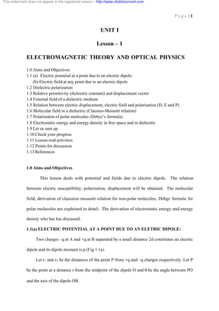
tetrachloride, is shown in fig 1.6a. We interpret that:
(i) The line for CCl4 is parallel to x-axis which shows that its molecules are
non-polar. It implies that the chlorine atoms in CCl4 are symmetrically
placed with respect to carbon atom, so that the center of gravity of negative
charges coincides with that of the positive charges and no permanent
dipoles are present.
(ii) The straight line for CHCl3 is inclined and shows the presence of polar
molecules. The polarity appears due to the charge asymmetry of the
molecule. The permanent dipole moment per unit volume is calculated
from the slope of the line. The dipole moment is then calculated on
dividing it by the number of dipoles per unit volume n. Constant a i is
determined from the intercept on y- axis.
31. This watermark does not appear in the registered version - http://www.clicktoconvert.com
P a g e | 31
Fig.1.6(a)
The study has been extended to a great number of molecules of monatomic gases like
Argon and molecules like H2 which are made up of two similar atoms. They do not
exhibit charge asymmetry and are therefore non-polar. But for molecules made up of
different atoms the charge asymmetry comes in and the molecules act like permanent
dipoles. The examples are NH3 , H2 O etc.
1.8 ELECTROSTATIC ENERGY AND ENERGY DENSITY IN FREE SPACE AND
IN DIELECTRIC
We shall first calculate the potential energy of a group of n point charges. It will be
equal to the work done in assembling the charges, bringing in one at a time.
If in the field of a stationary charge q1 , another charge q2 is brought from infinity to a
distance r12 = r1 - r2 then work done is
1 q1 q 2
DW2 = (1)
4pe 0 r12
=If a third charge q3 is brought from infinity to a point distant r13 and r23 from charges q1 and
q2 respectively then work done is
1 q1 q 2 1 q1 q 2
DW = + (2)
4pe 0 r 13 4pe 0 r23
From eqs. (1) and (2), the total work done in assembling the three charges is
32. This watermark does not appear in the registered version - http://www.clicktoconvert.com
P a g e | 32
DW = DW2 + DW3
1 é q1 q 2 qq qq ù
= ê + 1 2 + 1 2ú
4pe 0 ë r12 r 13 r23 û
which can be extended for an assembly of n charges as
1 é q1 q 2 q1 q 3 q 2 q3 qi q j ù
= ê + + + .......... + + .....ú (3)
4pe 0 ê r12
ë r13 r23 rij ú
û
1 n n 1 qi q j
=
2
å å i =1 j =1
4pe 0 rij
where the prime on the second summation implies that the terms i = j are to be excluded from
1
the sum. The factor has been introduced because of the fact that each pair of charges
2
occurs twice in the summation.
Equation (3) then represents the total electrostatic energy U of the assembly of n charges and
if we put
n 1 qi
å j =1
4pe 0 q j
= ji
In eqn. (3), we get
1 n
U=
2
å i =1
q ij i
If the point charges have been assembled in a linear dielectric medium, instead of vacuum or
free space, then free space permittivity e 0 is to be replaced by absolute permittivity e = e 0 er ,
where e r is the relative permittivity or dielectric constant of the medium.
Arbitrary Charge Distribution:
The expression for the field energy, U can be expressed with much advantage in terms of
volume and surface integrals involving the useful quantities electric field E and displacement
D when there is arbitrary charge distribution.
Let us consider a system of arbitrary charge distribution with density of initial charge
distribution asp. Let us remove the charge to infinity so that at any time the charge density is
ar where a is a parameter with values is ranging from unity to zero. At a point, where
density is ar, the charge dq’ in a volume element ‘dv’ will be
dq’ = (ar) dv (1)
and the potential f’ = af (2)
because f µ r and f is the initial potential at that point.
33. This watermark does not appear in the registered version - http://www.clicktoconvert.com
P a g e | 33
As the charge is removed to infinity, charge density at every point in the distribution will fall,
say, from ar to (a - da) r so that decrease in the charge contained in the volume element dv
will be
dq” = (da) r dv (3)
And the energy withdrawn from the system in removing this charge from volume element dv
is
dU = f’ dq” (4)
= (af) (da) r dv (5)
On using Eqs. (2) and (3).
If the whole charge from the system is removed to infinity i.e., the charge density is
reduced to zero everywhere then the total energy withdrawn, equal energy of the system, will
be
1
U = ò a da ò r f dv
0
v
1
æa 2 ö
U =ç
ç 2 ÷ òv r f dv
÷
è ø0
1
= ò r f dv
2 v
We know that r = div D
1
So that field energy is U= f div D dv
2ò
Further
div (fD) = f div D + D grad f
1
U= ò div (fD ) - D. grad f dv
2 v
so that
1 r r
= ò Ñ. (fD) - D.Ñ f dv
2 v
r
But E = - Ñ f,
1 r 1
so that U= ò Ñ. (fD) dv + 2 ò D.E dv
2 v v
34. This watermark does not appear in the registered version - http://www.clicktoconvert.com
P a g e | 34
Changing the first volume integral into surface integral by Gauss divergence theorem, we get
1 1
U= ò fD dS + 2 ò E.D dv (6)
2 s v
as v can be any volume which includes all the charges in the system, we can choose the
bounding surface S at large distance from the charge distribution. At large distances
1
fa
r
1
Da
r2
dS a r 2
1
so that ò f D. dS = r
S
®0 when r®¥
Eq. (6) is then left with
1
V = E.D dv
2ò
(7)
v
1
predicting that the energy is distributed with a density ( E.D ) per unit volume. Hence the
2
energy density i.e., the ener gy per unit volume in an electrostatic field is
1
u= ( E .D ) (8)
2
Eq. (7) holds for linear dielectrics.
Form linear dielectric,
D=eE
1
So that energy density is u= e E2 (9)
2
In free space e = e0 (since e r = 1), we have energy density of electrostatic field in free
1
space as given by u= e0 E2 (10)
2
Eqs. (8) and (9) hold good for isotropic homogeneous dielectric in which D and E are
proportional to each other. But if the medium is anisotropic, the permittivity e has different
values in different directions and consequently e which relates D and E is a tensor e 0b. The
relation can be written as