
Download to read offline
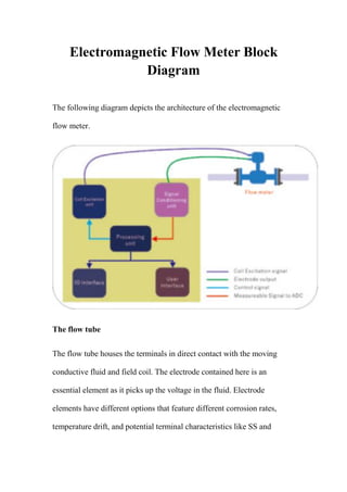


The electromagnetic flow meter block diagram depicts the main components of an electromagnetic flow meter. It includes the flow tube that houses the electrodes and field coil in contact with the moving fluid, the coil excitation system that produces the magnetic field, the signal conditioning unit that converts the electrode signals, the processing unit that generates control signals and provides readings, the IO interface that communicates with external devices, the user interface for manual operation, and the power supply unit that provides constant energy.


![[Envimart's Products] Đồng hồ điện từ đo lưu lượng nước, MagFlux hãng MJK](https://cdn.slidesharecdn.com/ss_thumbnails/en-305-magflux-datasheet-1711-190216143317-thumbnail.jpg?width=640&height=640&fit=bounds)


