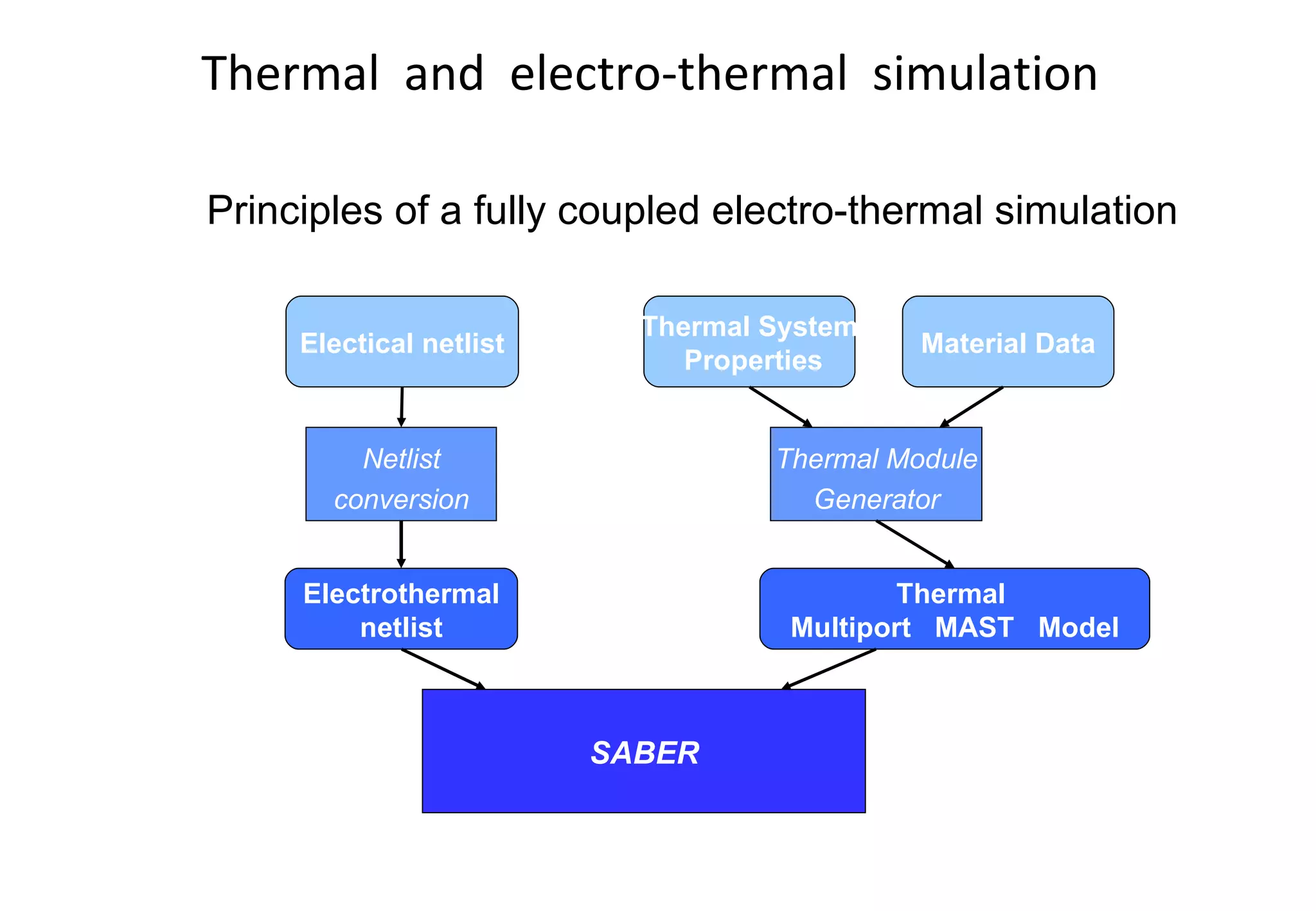
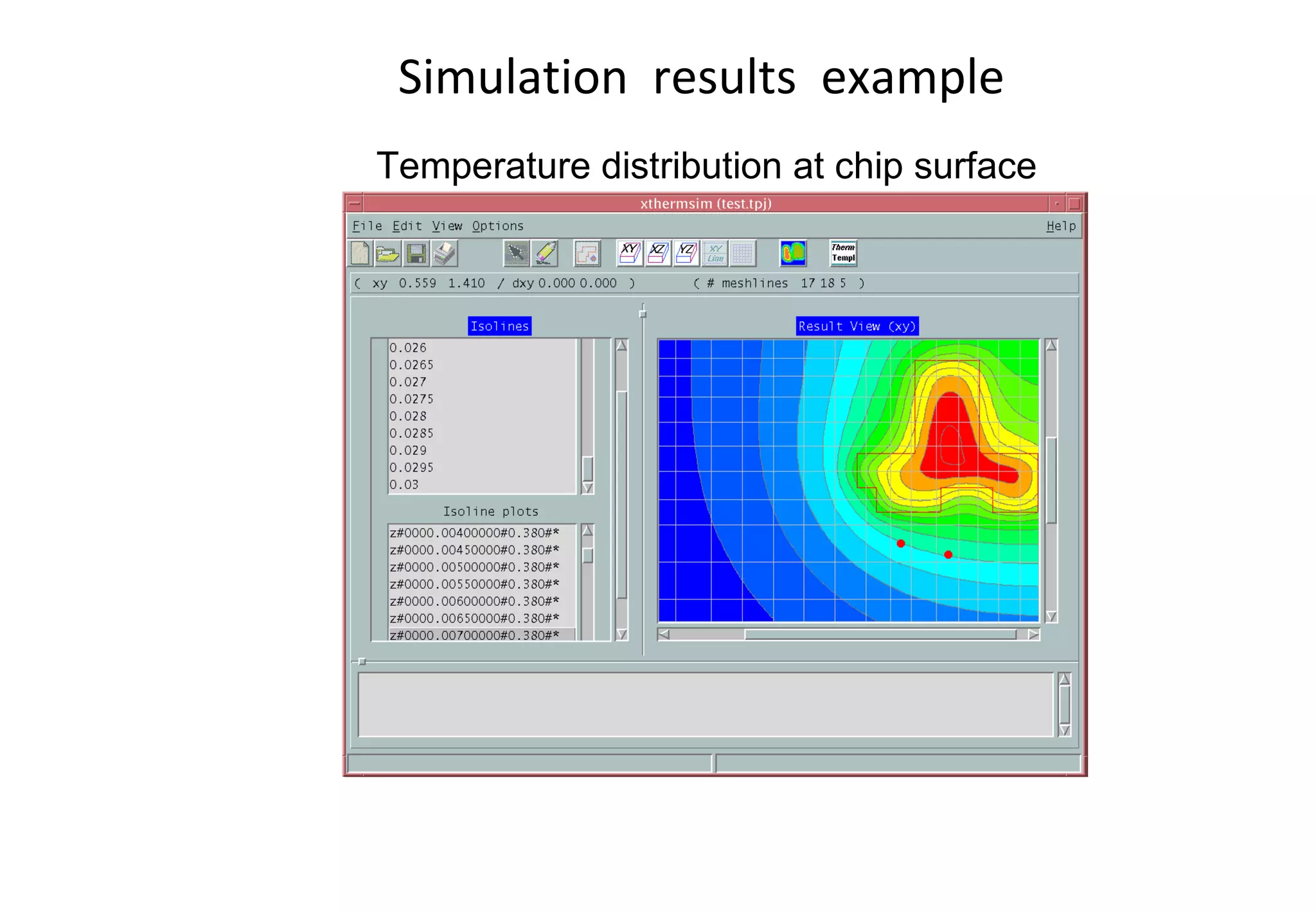
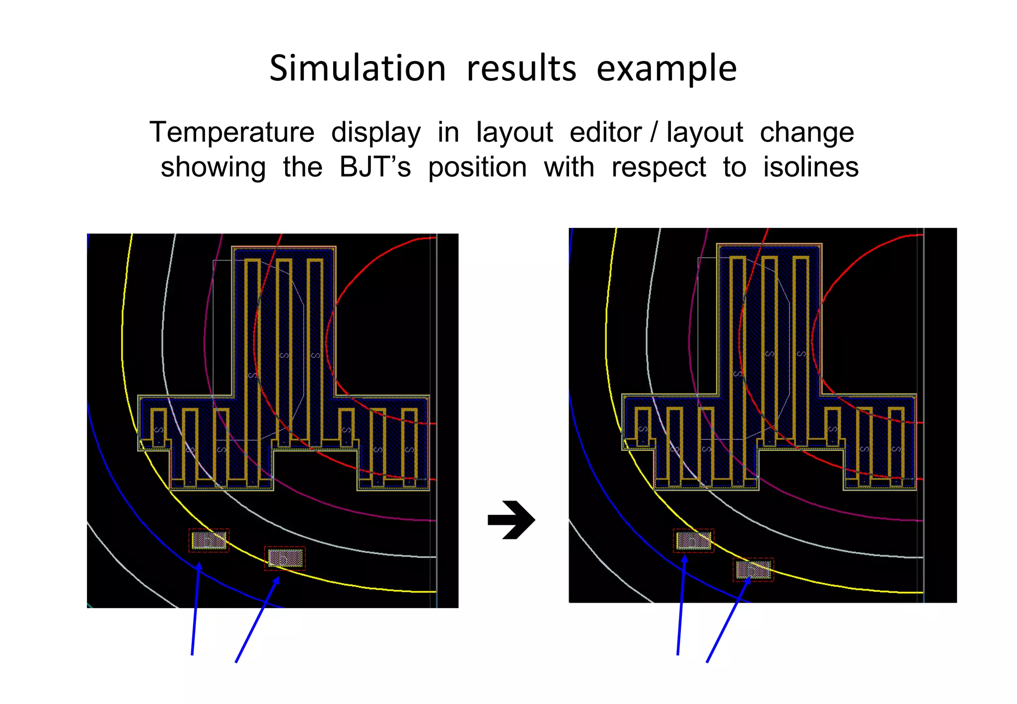
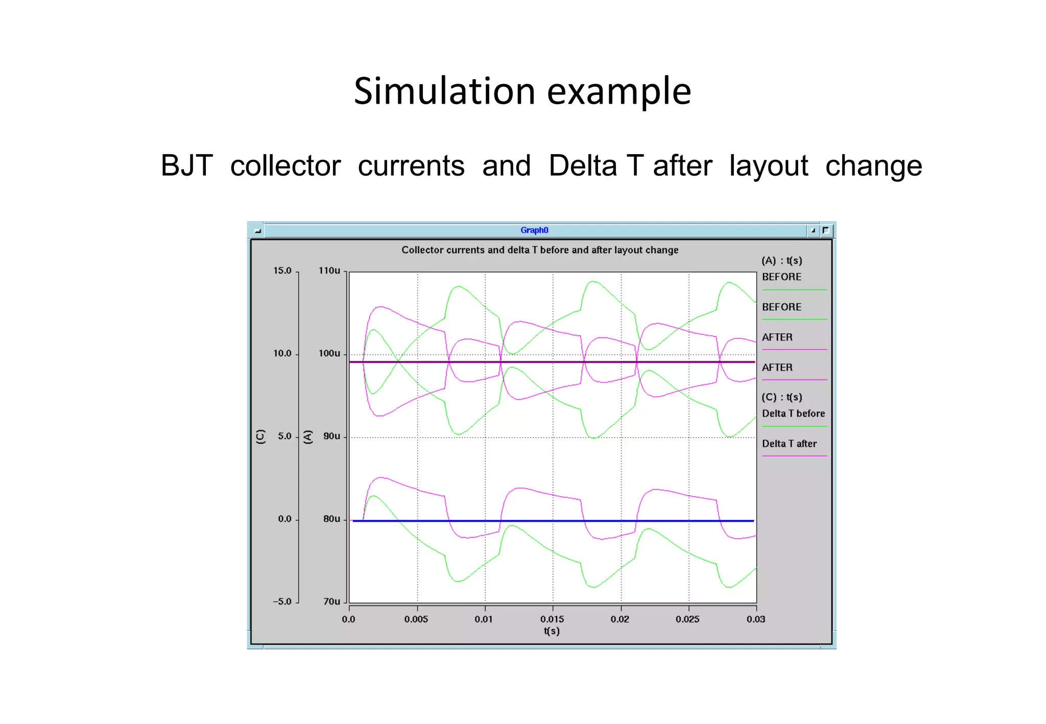
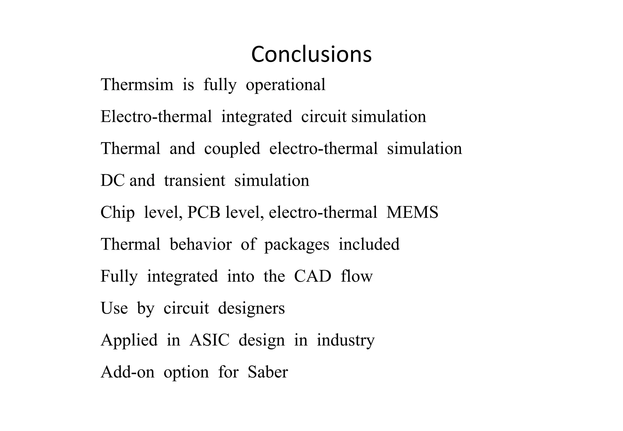
SlideShare a Scribd company logo
1 of 28
North  American  ASSURE Conference Portland, OR, May  15 - 17, 2002 Electro-thermal  IC  Simulation  with  Saber Presented  by  Michael  Domnitei, MSE E
Outline ,[object Object],[object Object],[object Object],[object Object],[object Object],[object Object],[object Object],[object Object]
Saber History ,[object Object],[object Object],[object Object],[object Object],[object Object],[object Object],[object Object]
What is Saber? ,[object Object],[object Object],[object Object],[object Object]
Why is Saber Unique? ,[object Object],[object Object],[object Object],[object Object]
Saber Tool Relationships 3 RD  Party Integrations 3 RD  Party Integrations Mixed-Technology Design Electrical System Design Saber Simulator Mixed-Technology Simulation Saber Sketch Design Capture Saber Harness Design Capture CosmosScope Plotting & Measurement InSpecs Advanced Analyses Model Libraries Saber Bundle 2-D Layout
What Types of Analyses can Saber do? ,[object Object],[object Object],[object Object],[object Object],[object Object],[object Object],[object Object],[object Object],[object Object],[object Object],[object Object],[object Object],[object Object],[object Object],[object Object],[object Object],[object Object],[object Object],[object Object],[object Object],[object Object],[object Object],[object Object],[object Object],[object Object]
[object Object],[object Object],[object Object],[object Object],[object Object],[object Object],[object Object],Benefits  of  the  thermal and electro-thermal  simulation during ASIC development
Observations ,[object Object],[object Object],[object Object],[object Object]
Integrated circuits as electro-thermal systems Electro-thermal system
Thermal and electro-thermal simulation Thermal multiport model Si  die,  package, environment Thermal multiport model T 1 T n T 2 P 1 P 2 P n Thermal simulation Thermal multiport model Electro- thermal netlist P 1 P 2 P n T 1 T n T 2 Electrothermal simulation
Thermal  and  electro-thermal  simulation SABER Netlist conversion Electical netlist Electrothermal netlist Thermal Module Generator Thermal System  Properties Thermal  Multiport  MAST  Model Material Data Principles of a fully coupled electro-thermal simulation
Thermal modeling with Thermsim Example of a 3D thermal simulation structure
Thermal modeling with Thermsim ,[object Object],[object Object],[object Object],Implemented as equivalent thermal RC-network Heat sources and monitor points on the chip surface Optional : temperature dependent material properties Optional : simple model for anisotropic thermal conductivity Optional : compact models for modelling package behavior Optional : Boundary Condition models (heat transfer coefficient for radiation and convection)
Simulation  features  of  Thermsim Thermal  simulation Fully  coupled  electro-thermal  simulation Steady  state  analysis Transient  analysis Simulation  with  Saber
Integration into the CAD environment ,[object Object],[object Object],[object Object],[object Object],[object Object],[object Object],[object Object],[object Object]
Integration in the CAD environment ,[object Object],[object Object],[object Object],[object Object],[object Object],[object Object]
CAD  environment  with  no  thermal  analysis Chip  Production Netlist Schematic entry tool Saber Layout editor Device model lib Spec Netlist
Thermsim  integration  into  the  CAD environment Electrothermal netlist Model instance  list Device geometries Isotherm data Saber simulation results Thermal multiport model template Thermal package library Thermsim GUI Chip  Production Schematic entry tool Saber Layout editor Device model lib Spec
Simulation  example Schematic   Layout
Simulation example Device temperatures
Simulation example DMOS I D (T) behavior
Simulation example BJT’s  collector  currents  and  their  temperature  difference
Simulation  results  example Temperature distribution at chip surface
Simulation  results  example Temperature  display  in  layout  editor / layout  change  showing  the  BJT’s  position  with  respect  to  isolines 
Simulation example BJT  collector  currents  and  Delta T after  layout  change
Conclusions ,[object Object],[object Object],[object Object],[object Object],[object Object],[object Object],[object Object],[object Object],[object Object],[object Object]
thermsim - el2eltherm

More Related Content

What's hot

Artificial intelligence in Energy and Utilities – Market Overview
Artificial intelligence in Energy and Utilities – Market OverviewArtificial intelligence in Energy and Utilities – Market Overview
Artificial intelligence in Energy and Utilities – Market OverviewIndigo Advisory Group
 
Challenges To Digital Transformation Training Ppt
Challenges To Digital Transformation Training PptChallenges To Digital Transformation Training Ppt
Challenges To Digital Transformation Training PptSlideTeam
 
Heat and Mass Transfer Data Book_6th edition_by C.P. Kothandaraman & S. Subra...
Heat and Mass Transfer Data Book_6th edition_by C.P. Kothandaraman & S. Subra...Heat and Mass Transfer Data Book_6th edition_by C.P. Kothandaraman & S. Subra...
Heat and Mass Transfer Data Book_6th edition_by C.P. Kothandaraman & S. Subra...Darawan Wahid
 
Digital Transformation: A $1 Trillion Opportunity (Note: 2015 deck - somewhat...
Digital Transformation: A $1 Trillion Opportunity (Note: 2015 deck - somewhat...Digital Transformation: A $1 Trillion Opportunity (Note: 2015 deck - somewhat...
Digital Transformation: A $1 Trillion Opportunity (Note: 2015 deck - somewhat...Ketan Kakkad
 
How-to-Make-Societies-Thrive-Report-Highlights.pdf
How-to-Make-Societies-Thrive-Report-Highlights.pdfHow-to-Make-Societies-Thrive-Report-Highlights.pdf
How-to-Make-Societies-Thrive-Report-Highlights.pdfStatsCommunications
 
Digital SMBs - Powering India into the Future
Digital SMBs - Powering India into the FutureDigital SMBs - Powering India into the Future
Digital SMBs - Powering India into the FutureZinnov
 
Informe de autorizacion opmi
Informe de autorizacion opmiInforme de autorizacion opmi
Informe de autorizacion opmiSadot Arones
 
Signage Steam Blowing
Signage Steam BlowingSignage Steam Blowing
Signage Steam BlowingSajid Ali
 
Virtual manufacturing systems ppt
Virtual manufacturing systems pptVirtual manufacturing systems ppt
Virtual manufacturing systems pptAnusha Chethana
 
Digital transformation in the manufacturing industry
Digital transformation in the manufacturing industryDigital transformation in the manufacturing industry
Digital transformation in the manufacturing industryBenji Harrison
 
Additive manufacturing Processes PDF by (badebhau4@gmail.com)
Additive manufacturing Processes PDF by (badebhau4@gmail.com)Additive manufacturing Processes PDF by (badebhau4@gmail.com)
Additive manufacturing Processes PDF by (badebhau4@gmail.com)Er. Bade Bhausaheb
 
BACS Standardisation Framework
BACS Standardisation FrameworkBACS Standardisation Framework
BACS Standardisation FrameworkLeonardo ENERGY
 
Finite Element Analysis Creo-Simulate Webinar
Finite Element Analysis Creo-Simulate WebinarFinite Element Analysis Creo-Simulate Webinar
Finite Element Analysis Creo-Simulate WebinarSanthosh N L
 
Engineering Applications of Machine Learning
Engineering Applications of Machine LearningEngineering Applications of Machine Learning
Engineering Applications of Machine LearningProf. Neeta Awasthy
 

What's hot (20)

Artificial intelligence in Energy and Utilities – Market Overview
Artificial intelligence in Energy and Utilities – Market OverviewArtificial intelligence in Energy and Utilities – Market Overview
Artificial intelligence in Energy and Utilities – Market Overview
 
Challenges To Digital Transformation Training Ppt
Challenges To Digital Transformation Training PptChallenges To Digital Transformation Training Ppt
Challenges To Digital Transformation Training Ppt
 
Heat and Mass Transfer Data Book_6th edition_by C.P. Kothandaraman & S. Subra...
Heat and Mass Transfer Data Book_6th edition_by C.P. Kothandaraman & S. Subra...Heat and Mass Transfer Data Book_6th edition_by C.P. Kothandaraman & S. Subra...
Heat and Mass Transfer Data Book_6th edition_by C.P. Kothandaraman & S. Subra...
 
Digital Transformation: A $1 Trillion Opportunity (Note: 2015 deck - somewhat...
Digital Transformation: A $1 Trillion Opportunity (Note: 2015 deck - somewhat...Digital Transformation: A $1 Trillion Opportunity (Note: 2015 deck - somewhat...
Digital Transformation: A $1 Trillion Opportunity (Note: 2015 deck - somewhat...
 
How-to-Make-Societies-Thrive-Report-Highlights.pdf
How-to-Make-Societies-Thrive-Report-Highlights.pdfHow-to-Make-Societies-Thrive-Report-Highlights.pdf
How-to-Make-Societies-Thrive-Report-Highlights.pdf
 
Digital SMBs - Powering India into the Future
Digital SMBs - Powering India into the FutureDigital SMBs - Powering India into the Future
Digital SMBs - Powering India into the Future
 
Sales slide deck
Sales slide deckSales slide deck
Sales slide deck
 
E bike market
E bike marketE bike market
E bike market
 
Artificial Intelligence in Manufacturing
Artificial Intelligence in ManufacturingArtificial Intelligence in Manufacturing
Artificial Intelligence in Manufacturing
 
Informe de autorizacion opmi
Informe de autorizacion opmiInforme de autorizacion opmi
Informe de autorizacion opmi
 
Spray metal tooling
Spray metal toolingSpray metal tooling
Spray metal tooling
 
Signage Steam Blowing
Signage Steam BlowingSignage Steam Blowing
Signage Steam Blowing
 
Virtual manufacturing systems ppt
Virtual manufacturing systems pptVirtual manufacturing systems ppt
Virtual manufacturing systems ppt
 
Digital transformation in the manufacturing industry
Digital transformation in the manufacturing industryDigital transformation in the manufacturing industry
Digital transformation in the manufacturing industry
 
Flexão lista 1
Flexão lista 1   Flexão lista 1
Flexão lista 1
 
Additive manufacturing Processes PDF by (badebhau4@gmail.com)
Additive manufacturing Processes PDF by (badebhau4@gmail.com)Additive manufacturing Processes PDF by (badebhau4@gmail.com)
Additive manufacturing Processes PDF by (badebhau4@gmail.com)
 
BACS Standardisation Framework
BACS Standardisation FrameworkBACS Standardisation Framework
BACS Standardisation Framework
 
Finite Element Analysis Creo-Simulate Webinar
Finite Element Analysis Creo-Simulate WebinarFinite Element Analysis Creo-Simulate Webinar
Finite Element Analysis Creo-Simulate Webinar
 
Engineering Applications of Machine Learning
Engineering Applications of Machine LearningEngineering Applications of Machine Learning
Engineering Applications of Machine Learning
 
ind engg and mgmt O P KHANNA.pdf
ind engg and mgmt  O P KHANNA.pdfind engg and mgmt  O P KHANNA.pdf
ind engg and mgmt O P KHANNA.pdf
 

Viewers also liked

Livre blanc affiliation - Public Idées - 2012
Livre blanc affiliation - Public Idées - 2012Livre blanc affiliation - Public Idées - 2012
Livre blanc affiliation - Public Idées - 2012Romain Fonnier
 
Menschlich, zukunftsweisend, transparent - die GLS Bank
Menschlich, zukunftsweisend, transparent - die GLS BankMenschlich, zukunftsweisend, transparent - die GLS Bank
Menschlich, zukunftsweisend, transparent - die GLS BankGLS Bank
 
Session 2 maica rubinat (pafes)
Session 2 maica rubinat (pafes)Session 2 maica rubinat (pafes)
Session 2 maica rubinat (pafes)lindsaycess
 
Petr Majerik, Zenith OptiMedia, MediaTalk 11th January 2011
Petr Majerik, Zenith OptiMedia, MediaTalk 11th January 2011Petr Majerik, Zenith OptiMedia, MediaTalk 11th January 2011
Petr Majerik, Zenith OptiMedia, MediaTalk 11th January 2011Pavlína Louženská
 
Golden 20’s
Golden 20’sGolden 20’s
Golden 20’sEfi Tirle
 
Gps glonass
Gps glonassGps glonass
Gps glonasssenarap
 
Programma FINALE incontro GIFI 19 febbraio 2013
Programma FINALE incontro GIFI 19 febbraio 2013Programma FINALE incontro GIFI 19 febbraio 2013
Programma FINALE incontro GIFI 19 febbraio 2013GIFI
 
General knowledge[1]
General knowledge[1]General knowledge[1]
General knowledge[1]feca2000
 
The monsters university
The monsters universityThe monsters university
The monsters universitymaricagomez15
 
El buen humor herramienta que te ayuda a
El buen humor herramienta que te ayuda aEl buen humor herramienta que te ayuda a
El buen humor herramienta que te ayuda aIsabel Ojeda
 
Presentacion huerto social albayzin - capi albayzin
Presentacion   huerto social albayzin - capi albayzinPresentacion   huerto social albayzin - capi albayzin
Presentacion huerto social albayzin - capi albayzinGuadalinfo Albayzin
 
EN 50136 Alarmtransmission monitoring with Analytic tools
EN 50136 Alarmtransmission monitoring with Analytic toolsEN 50136 Alarmtransmission monitoring with Analytic tools
EN 50136 Alarmtransmission monitoring with Analytic toolsPeter Monte
 
James Rodriguez el ídolo de un país
James Rodriguez el ídolo de un paísJames Rodriguez el ídolo de un país
James Rodriguez el ídolo de un paísalexanderweb
 
Difusor Fragancias Centhylon
Difusor Fragancias CenthylonDifusor Fragancias Centhylon
Difusor Fragancias CenthylonCenthylon
 

Viewers also liked (20)

Livre blanc affiliation - Public Idées - 2012
Livre blanc affiliation - Public Idées - 2012Livre blanc affiliation - Public Idées - 2012
Livre blanc affiliation - Public Idées - 2012
 
Menschlich, zukunftsweisend, transparent - die GLS Bank
Menschlich, zukunftsweisend, transparent - die GLS BankMenschlich, zukunftsweisend, transparent - die GLS Bank
Menschlich, zukunftsweisend, transparent - die GLS Bank
 
Session 2 maica rubinat (pafes)
Session 2 maica rubinat (pafes)Session 2 maica rubinat (pafes)
Session 2 maica rubinat (pafes)
 
Coltan3
Coltan3Coltan3
Coltan3
 
Semana de la biblia
Semana de la bibliaSemana de la biblia
Semana de la biblia
 
Petr Majerik, Zenith OptiMedia, MediaTalk 11th January 2011
Petr Majerik, Zenith OptiMedia, MediaTalk 11th January 2011Petr Majerik, Zenith OptiMedia, MediaTalk 11th January 2011
Petr Majerik, Zenith OptiMedia, MediaTalk 11th January 2011
 
Golden 20’s
Golden 20’sGolden 20’s
Golden 20’s
 
Public Meeting #2 Information Materials
Public Meeting #2 Information MaterialsPublic Meeting #2 Information Materials
Public Meeting #2 Information Materials
 
Gps glonass
Gps glonassGps glonass
Gps glonass
 
Boletin convocatorias empleo 150303
Boletin convocatorias empleo 150303Boletin convocatorias empleo 150303
Boletin convocatorias empleo 150303
 
Programma FINALE incontro GIFI 19 febbraio 2013
Programma FINALE incontro GIFI 19 febbraio 2013Programma FINALE incontro GIFI 19 febbraio 2013
Programma FINALE incontro GIFI 19 febbraio 2013
 
General knowledge[1]
General knowledge[1]General knowledge[1]
General knowledge[1]
 
The monsters university
The monsters universityThe monsters university
The monsters university
 
El buen humor herramienta que te ayuda a
El buen humor herramienta que te ayuda aEl buen humor herramienta que te ayuda a
El buen humor herramienta que te ayuda a
 
Presentacion huerto social albayzin - capi albayzin
Presentacion   huerto social albayzin - capi albayzinPresentacion   huerto social albayzin - capi albayzin
Presentacion huerto social albayzin - capi albayzin
 
EN 50136 Alarmtransmission monitoring with Analytic tools
EN 50136 Alarmtransmission monitoring with Analytic toolsEN 50136 Alarmtransmission monitoring with Analytic tools
EN 50136 Alarmtransmission monitoring with Analytic tools
 
EMS Holiday 2013 Recap
EMS Holiday 2013 RecapEMS Holiday 2013 Recap
EMS Holiday 2013 Recap
 
James Rodriguez el ídolo de un país
James Rodriguez el ídolo de un paísJames Rodriguez el ídolo de un país
James Rodriguez el ídolo de un país
 
Mi-ST
Mi-STMi-ST
Mi-ST
 
Difusor Fragancias Centhylon
Difusor Fragancias CenthylonDifusor Fragancias Centhylon
Difusor Fragancias Centhylon
 

Similar to Electro Thermal IC Simulation With Saber

Chapter 4: Induction Heating Computer Simulation
Chapter 4: Induction Heating Computer SimulationChapter 4: Induction Heating Computer Simulation
Chapter 4: Induction Heating Computer SimulationFluxtrol Inc.
 
Thermal Resistance Modelling with SimScale
Thermal Resistance Modelling with SimScaleThermal Resistance Modelling with SimScale
Thermal Resistance Modelling with SimScaleSimScale
 
End to End Self-Heating Analysis Methodology and Toolset for High Performance...
End to End Self-Heating Analysis Methodology and Toolset for High Performance...End to End Self-Heating Analysis Methodology and Toolset for High Performance...
End to End Self-Heating Analysis Methodology and Toolset for High Performance...Arun Joseph
 
Public cielution imaps_chip_to_system_codesign
Public cielution imaps_chip_to_system_codesignPublic cielution imaps_chip_to_system_codesign
Public cielution imaps_chip_to_system_codesignKamal Karimanal
 
Case study: Design Space Exploration for Electronic Cooling simulation
Case study: Design Space Exploration for Electronic Cooling simulationCase study: Design Space Exploration for Electronic Cooling simulation
Case study: Design Space Exploration for Electronic Cooling simulationSuzana Djurcilov
 
Thermal Analysis webinar
Thermal Analysis webinarThermal Analysis webinar
Thermal Analysis webinarhamishlewis
 
Karimanal thrml co_design_itherm2010_final
Karimanal thrml co_design_itherm2010_finalKarimanal thrml co_design_itherm2010_final
Karimanal thrml co_design_itherm2010_finalKamal Karimanal
 
A Review on Thermal Aware Optimization of Three Dimensional Integrated Circui...
A Review on Thermal Aware Optimization of Three Dimensional Integrated Circui...A Review on Thermal Aware Optimization of Three Dimensional Integrated Circui...
A Review on Thermal Aware Optimization of Three Dimensional Integrated Circui...IJMER
 
Thermal Reliability for FinFET based Designs
Thermal Reliability for FinFET based DesignsThermal Reliability for FinFET based Designs
Thermal Reliability for FinFET based DesignsAnsys
 
EELE 5331 Digital ASIC DesignLab ManualDr. Yushi Zhou.docx
EELE 5331 Digital ASIC DesignLab ManualDr. Yushi Zhou.docxEELE 5331 Digital ASIC DesignLab ManualDr. Yushi Zhou.docx
EELE 5331 Digital ASIC DesignLab ManualDr. Yushi Zhou.docxtoltonkendal
 
Fast Insights to Optimized Vectorization and Memory Using Cache-aware Rooflin...
Fast Insights to Optimized Vectorization and Memory Using Cache-aware Rooflin...Fast Insights to Optimized Vectorization and Memory Using Cache-aware Rooflin...
Fast Insights to Optimized Vectorization and Memory Using Cache-aware Rooflin...Intel® Software
 
Nilesh ranpura systemmodelling
Nilesh ranpura systemmodellingNilesh ranpura systemmodelling
Nilesh ranpura systemmodellingObsidian Software
 
How to Select Hardware for Internet of Things Systems?
How to Select Hardware for Internet of Things Systems?How to Select Hardware for Internet of Things Systems?
How to Select Hardware for Internet of Things Systems?Hannes Tschofenig
 
How to achieve 95%+ Accurate power measurement during architecture exploration?
How to achieve 95%+ Accurate power measurement during architecture exploration? How to achieve 95%+ Accurate power measurement during architecture exploration?
How to achieve 95%+ Accurate power measurement during architecture exploration? Deepak Shankar
 
hyperlynx_compress.pdf
hyperlynx_compress.pdfhyperlynx_compress.pdf
hyperlynx_compress.pdfraimonribal
 
Thinking Outside the Box – Server Design for #DataCenter Optimization
Thinking Outside the Box – Server Design for #DataCenter OptimizationThinking Outside the Box – Server Design for #DataCenter Optimization
Thinking Outside the Box – Server Design for #DataCenter OptimizationRobert Schmidt
 
Engys Presentation Harshad Joshi September 2018
Engys Presentation Harshad Joshi September 2018Engys Presentation Harshad Joshi September 2018
Engys Presentation Harshad Joshi September 2018IES VE
 

Similar to Electro Thermal IC Simulation With Saber (20)

Chapter 4: Induction Heating Computer Simulation
Chapter 4: Induction Heating Computer SimulationChapter 4: Induction Heating Computer Simulation
Chapter 4: Induction Heating Computer Simulation
 
Thermal Resistance Modelling with SimScale
Thermal Resistance Modelling with SimScaleThermal Resistance Modelling with SimScale
Thermal Resistance Modelling with SimScale
 
End to End Self-Heating Analysis Methodology and Toolset for High Performance...
End to End Self-Heating Analysis Methodology and Toolset for High Performance...End to End Self-Heating Analysis Methodology and Toolset for High Performance...
End to End Self-Heating Analysis Methodology and Toolset for High Performance...
 
Public cielution imaps_chip_to_system_codesign
Public cielution imaps_chip_to_system_codesignPublic cielution imaps_chip_to_system_codesign
Public cielution imaps_chip_to_system_codesign
 
Case study: Design Space Exploration for Electronic Cooling simulation
Case study: Design Space Exploration for Electronic Cooling simulationCase study: Design Space Exploration for Electronic Cooling simulation
Case study: Design Space Exploration for Electronic Cooling simulation
 
Thermal Analysis webinar
Thermal Analysis webinarThermal Analysis webinar
Thermal Analysis webinar
 
EnergyPlus
EnergyPlusEnergyPlus
EnergyPlus
 
Engineering_capabilities_2015
Engineering_capabilities_2015Engineering_capabilities_2015
Engineering_capabilities_2015
 
Karimanal thrml co_design_itherm2010_final
Karimanal thrml co_design_itherm2010_finalKarimanal thrml co_design_itherm2010_final
Karimanal thrml co_design_itherm2010_final
 
A Review on Thermal Aware Optimization of Three Dimensional Integrated Circui...
A Review on Thermal Aware Optimization of Three Dimensional Integrated Circui...A Review on Thermal Aware Optimization of Three Dimensional Integrated Circui...
A Review on Thermal Aware Optimization of Three Dimensional Integrated Circui...
 
Thermal Reliability for FinFET based Designs
Thermal Reliability for FinFET based DesignsThermal Reliability for FinFET based Designs
Thermal Reliability for FinFET based Designs
 
EELE 5331 Digital ASIC DesignLab ManualDr. Yushi Zhou.docx
EELE 5331 Digital ASIC DesignLab ManualDr. Yushi Zhou.docxEELE 5331 Digital ASIC DesignLab ManualDr. Yushi Zhou.docx
EELE 5331 Digital ASIC DesignLab ManualDr. Yushi Zhou.docx
 
Fast Insights to Optimized Vectorization and Memory Using Cache-aware Rooflin...
Fast Insights to Optimized Vectorization and Memory Using Cache-aware Rooflin...Fast Insights to Optimized Vectorization and Memory Using Cache-aware Rooflin...
Fast Insights to Optimized Vectorization and Memory Using Cache-aware Rooflin...
 
Nilesh ranpura systemmodelling
Nilesh ranpura systemmodellingNilesh ranpura systemmodelling
Nilesh ranpura systemmodelling
 
How to Select Hardware for Internet of Things Systems?
How to Select Hardware for Internet of Things Systems?How to Select Hardware for Internet of Things Systems?
How to Select Hardware for Internet of Things Systems?
 
How to achieve 95%+ Accurate power measurement during architecture exploration?
How to achieve 95%+ Accurate power measurement during architecture exploration? How to achieve 95%+ Accurate power measurement during architecture exploration?
How to achieve 95%+ Accurate power measurement during architecture exploration?
 
PCB Virtual Prototyping with PSpice
PCB Virtual Prototyping with PSpicePCB Virtual Prototyping with PSpice
PCB Virtual Prototyping with PSpice
 
hyperlynx_compress.pdf
hyperlynx_compress.pdfhyperlynx_compress.pdf
hyperlynx_compress.pdf
 
Thinking Outside the Box – Server Design for #DataCenter Optimization
Thinking Outside the Box – Server Design for #DataCenter OptimizationThinking Outside the Box – Server Design for #DataCenter Optimization
Thinking Outside the Box – Server Design for #DataCenter Optimization
 
Engys Presentation Harshad Joshi September 2018
Engys Presentation Harshad Joshi September 2018Engys Presentation Harshad Joshi September 2018
Engys Presentation Harshad Joshi September 2018
 

Electro Thermal IC Simulation With Saber

  • 1. North American ASSURE Conference Portland, OR, May 15 - 17, 2002 Electro-thermal IC Simulation with Saber Presented by Michael Domnitei, MSE E
  • 2.
  • 3.
  • 4.
  • 5.
  • 6. Saber Tool Relationships 3 RD Party Integrations 3 RD Party Integrations Mixed-Technology Design Electrical System Design Saber Simulator Mixed-Technology Simulation Saber Sketch Design Capture Saber Harness Design Capture CosmosScope Plotting & Measurement InSpecs Advanced Analyses Model Libraries Saber Bundle 2-D Layout
  • 7.
  • 8.
  • 9.
  • 10. Integrated circuits as electro-thermal systems Electro-thermal system
  • 11. Thermal and electro-thermal simulation Thermal multiport model Si die, package, environment Thermal multiport model T 1 T n T 2 P 1 P 2 P n Thermal simulation Thermal multiport model Electro- thermal netlist P 1 P 2 P n T 1 T n T 2 Electrothermal simulation
  • 12. Thermal and electro-thermal simulation SABER Netlist conversion Electical netlist Electrothermal netlist Thermal Module Generator Thermal System Properties Thermal Multiport MAST Model Material Data Principles of a fully coupled electro-thermal simulation
  • 13. Thermal modeling with Thermsim Example of a 3D thermal simulation structure
  • 14.
  • 15. Simulation features of Thermsim Thermal simulation Fully coupled electro-thermal simulation Steady state analysis Transient analysis Simulation with Saber
  • 16.
  • 17.
  • 18. CAD environment with no thermal analysis Chip Production Netlist Schematic entry tool Saber Layout editor Device model lib Spec Netlist
  • 19. Thermsim integration into the CAD environment Electrothermal netlist Model instance list Device geometries Isotherm data Saber simulation results Thermal multiport model template Thermal package library Thermsim GUI Chip Production Schematic entry tool Saber Layout editor Device model lib Spec
  • 20. Simulation example Schematic Layout
  • 22. Simulation example DMOS I D (T) behavior
  • 23. Simulation example BJT’s collector currents and their temperature difference
  • 24. Simulation results example Temperature distribution at chip surface
  • 25. Simulation results example Temperature display in layout editor / layout change showing the BJT’s position with respect to isolines 
  • 26. Simulation example BJT collector currents and Delta T after layout change
  • 27.

Editor's Notes

  1. What you are about to see here is the presentation of a new tool based on Saber for thermal and fully electro-thermal circuit simulations. The name of this tool is Thermsim and has been developed by a team from Bosch in Reutlingen, Germany. Historically speaking, there has been a lots of research in the area of electro-thermal circuit simulations, but the Bosch case is the first one to be fully integrated in a CAD design environment. Thermsim can be used to determine the temp. distribution on chip level and investigate electro-thermal coupling in integrated circuits. We are going to mention a few words about IC’s as electro-thermal systems and go over the thermal modeling and the flow of electro-thermal simulation.Then, we’ll take a look at the integration of Thermsim in the CAD environment. We will also look at an example of application using this tool. Finally, we’ll reach our conclusions about the potential use and advantages of thermsim.
  2. Semiconductors dissipate power and 'adding bigger fans' is not always a desirable nor feasable solution to fix thermal problems. This will e.g. not solve the risks of thermal crosstalk." Change "minimized" into "optimized" in this line! Minimizing the thermal resistance is not (!) always a design goal. On chip level, minimizing Rth means larger area of driver stages and that increases cost. So the task is to _optimize_ the Rth, meaning we have to find the minimum device area that has still acceptable thermal resistance.
  3. Many Integrated Circuits (in - for instance - the industrial, automotive, consumer electronics) should be considered as electro-thermal systems. The electrical part is formed by the circuit as defined by its circuit diagram. This circuit is physically defined by the layout in a suitable technology. The physical design defines the geometries and positions of the devices in the circuit which have strong impact on the temperature rise due to self heating in dissipating devices and due to thermal cross talk. The IC-package and the complete system also strongly determine the thermal behavior. The link between the electrical and thermal behavior is that the electrical device characteristics are temperature dependent. Therefore the thermal system behavior is coupled to the electrical system and unwanted coupling may lead to circuit failure.
  4. The thermal system (consisting of Silicon die, package and its thermal environment) can be considered as a thermal multiport. The terminals of this multiport are: one connection for each device whose thermal behavior has to be simulated. A thermal heat flow („dissipated power“) will be flowing into these terminals as through variable and the model of the thermal system will deliver a temperature as the results of these heatflows (temperature is the accross variable). The temperature at each terminal gives the temperature of the corresponding device. Principally, this kind of thermal multiport model can be used for purely thermal simulation as well as for coupled electrothermal simulation . In the first case ideal thermal heat sources are connected to the thermal model. In the second case, an electro-thermal netlist is connected to the model.
  5. As shown on the previous slide in an coupled electro thermal simulation an electro-thermal netlist is coupled with an model for the thermal system behavior. This slide shows this coupling. The left branch of the figure shows that a normal electrical netlist is converted into an electro-thermal netlist. This conversion step is carried out automatically, if an electrothermal simulation has to be done. The devices in the original electrical netlist that are to be simulated electrothermally will be labeled by an additional attribute. The netlist transformation/conversion will replace the labeled device instances by an electrothermal device model which have an additional thermal pin. All device instances with thermal pins will be connected to an instance of the thermal system model (the „thermal multi-port model“) of the previous slide. The MAST model for the thermal multi-port (right branch) is generated depending on thermal system properties, such as the device geometry, package details, thermal boundary conditions, material data. The simulation is done by Saber.
  6. This slide shows an example of the physical structure which is described by a thermal model. Basically the thermal models consist of box-shaped regions. In this example the green box at the bottom is a alumium base plate . On top of this a ceramic substrate (blue region) has been glued ( glue layer is a very thin intermediate layer not well visible on the scale of the figure). On the ceramic a Si die (red) is glued (thin green intermediate glue layer). On the top surface of the die, the yellow shapes are the 9 different heat sources , present on this IC. The little green dots are so called monitor points where the temp. can be monitored for postprocessing or thermally dependent devices (that do not act as heatsources because their dissipation is negligible) may be affected by temp. Thermal boundary conditions can be defined at the surfaces of the regions. In this example a constant temperature boundary condition was used at the bottom of the base plate. This way an ideal heat sink at the bottom is modeled.
  7. This slide discusses some implementation details of the thermal model. The model solves the differential equation for describing the heat flow by diffusion in the solid. This equation is solved matematically as a Finite Difference (FD) Model. Thus, it is a physical model! The FD Model is implemented as an equivalent thermal RC-network. Heat sources (dissipating devices) and monitor points (non-dissipating devices, but thermally dependent) are defined at the surface. There are several important modeling options: T-Dependent thermal material properties: e.g. Silicon‘s thermal conductivity is strongly temperature dependent. Thermal conductivity may get different values in different directions (anisotropy) (think about metal planes in a PCB) Thermal compact models can be added as boundary conditions. This way more efficient behavioral type of models can be used. As boudary conditions one can define not only constant temperatures but also heat transfer coefficient models to model - for instance - the heat removal by radiation and convection.
  8. This slide summarizes the main features of Thermsim: Thermsim gives the option of both thermal and fully coupled electro-thermal simulation. These analysis may be in the steady state regime or transient regime. Even small signal AC is possible, although less relevant in most cases. The simulation is completely carried out with Saber , so the main benefit of thermsim is the integration of thermal simulation in a IC design environ. Providing an easy method for fast thermal and electro-thermal simulation and the capability of carrying out fully coupled electro-thermal circuit simulations.
  9. Thermsim - the thermal simulation add-on package for Saber - has been fully integrated into the ASIC design flow. The main objectives of this integration is to make an electro-thermal simulation option available to circuit designers, who are usually not experts for thermal analysis. If designers have such a tool they can carry out thermal analysis themselves and therefore shorter design validation times can be accomplished. In order to make the tool usable for IC designers it has been fully integrated into the design flow. Where possible, it uses the tools from the conventional design flow. Functionality that could not be integrated into the standard tools has been implemented into a GUI. Furthermore, important and possibly error prone tasks, such as generation of electrothermal netlists, has been automated.
  10. The main new functionality, in addition to the standard design flow is the generation of thermal models. A flexible model generator is written. The visualization (2 D Isotherm plots showing the temperature distribution in the chip) is integrated into the GUI too. Conversion of electrical into electro-thermal netlists is done in the background after a netlist is written by the schematic entry tool. A possiblilty to export thermal data (to external post - processing tools) or isotherm shapes (to display temperature distributions in the layout) is provided. The interface with the layout editor enables the extraction of device shapes from an available layout or the display of simulated isotherms in the layout. This interface is based on ASCII files, the extraction and isotherm display code has been inplemented as userware in the layout editor.
  11. This slide shows the standard design flow. The circuit that is entered in the schematic entry tool outputs a netlist. This netlist is first used to simulate the electrical behavior of the electronic circuit, to verify that the electrical specs are met. If the circuit design has been completed, the netlist is used to draw the physical design in the layout editor. Finally this will result in a mask set and now the IC can be processed.
  12. Slide 14:This slide shows the extension to the design flow in order to simulate electro-thermally and to have thermal constraint data visually available in the layout editor. Here again, an electronic system is entered into the schematic entry tool. Now, an electro-thermal netlist is generated, instead of an electrical netlist. This netlist contains an instance of a thermal multiport model that has to be generated for this particular simulation case. This model generation is one of the functions of the Thermsim GUI. In the GUI the positions of the devices that are to be simulated electro-thermally are drawn (to know which devices have to be drawn, a file containing the identifiers of the model instances is imported into the GUI). The thermal model behavior also depends on the type of package that is selected for this case. The package model templates are stored in a package model library. Once the thermal multiport model is generated the electrothermal simulation can be performed. After simulation the results can be viewed with Saber Scope. The temperature distribution on e.g. the chip surface can be visualized as 2D isotherm plots using the Thermsim GUI. Furthermore the interface between Thermsim and the layout editor are shown: the possibility to extract device geometries from the layout and the possibility to display simulated temperature distributions in the layout.
  13. Slide 15:This slides shows a simple yet illustrative example of an electro thermal simulation case. The schematic contains a power DMOS transistor that has a pulsed gate voltage signal. The other part of the circuit consists of a differential bipolar transistor pair with shorted bases (delta Vbe=0) In case both transistors have equal temperatures, their collector currents are equal. The devices in this example all have an attribute "thermal" to label them as electro-thermally relevant devices and to include them in the electro-thermal analysis. The layout plot shows the irregularly shaped DMOS and the 2 smaller bipolar transistors at its side. Thermal coupled = will disipate heat and also be affected by heat., thermal dependent = will be affected by heat.
  14. Slide 16: This graph shows the simulated temperature of the DMOS (upper curve). The self heating and cooling down due to the pulsed power dissipation is clearly visible. The lower curves show the temperatures of the bipolar transistors, which are heated up because of the thermal cross talk with the nearby DMOS. We see that the paired transistors have slightly different temperatures and that their temperature difference (and its sign) is varying as a function of time.
  15. Slide 17:This slide shows the power dissipation in the DMOS (lower curve) and the temp. of this device (upper curve, which was also shown in the previous slide). Clearly visible is the dependence of the power dissipation on the temperature. This is due to the temperature dependence of the drain current of a MOS device (Ids decreases with increasing temperature). Such an effect can only be simulated accurately when taking the full electro thermal coupling into account! Without electro-thermal coupling the peak power levels of the DMOS would have been constant during time.
  16. This graph shows the temperature difference between the two bipolar transistors (lower curve). Because there is a temperature difference between them, the collector currents are not equal (upper two curves). The differences between the collector currents are changing depending on the sign and the amount of the temperature difference. This again can only be simulated with an electro-thermal simulation tool such as Thermsim. Without taking electro-thermal coupling into account, the collector current would have been equal.
  17. Slide 19: This slide illustrates the visualization of the temperature distribution on the chip surface. Isotherm plots can be viewed for different cross-sections of the die and at different time points of the simulation. It is possible to visualize the time evolution of the temperature by animated movies of isotherm plots. Then you have the nice thermal movie again.
  18. Slide 20: The left graph shows the initial placement of the bipolar transistors in the layout. Because they are not positioned on an isotherm they experience a slightly different temperature, as was seen in the previous slides. Now, the availability of thermal information allows us to optimize the position of the bipolar to reduce there temperature difference (right graph).
  19. Slide 21: After repositioning of the bipolar transistors the temperature differences are much reduced (lower curve) and hence the difference between the collector currents have become considerably smaller (upper curves).
  20. Point 4: Here, it's good to emphasize that transient thermal simulation is especially important, because chip designers can usually estimate the static thermal resistance quite well, but tend to largely overestimate the *transient* temperature increases. Here thermal analysis can be a great help to reduce chip area and cost, by preventing over-dimensioning of power drivers. Regarding point 5 (chip, PCB, MEMS): the present implementation in the Bosch design environment (especially the GUI) is putting emphasis on silicon die and its package as the thermal model (as presented in this talk). However, in principle, the modeling approach and package use is not limited to this and may as well be used for MEMS and PCBs.
  21. This slide shows the conversion of an electrical netlist into an electro-thermal netlist. The black writing is the original electrical netlist. The red characters have been added by the conversion routine