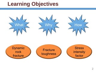
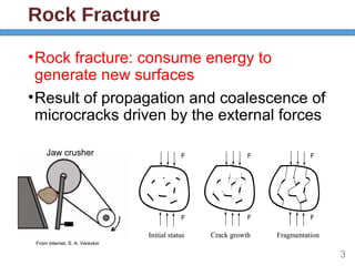
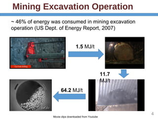
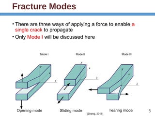
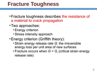
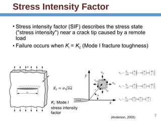
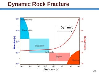
Dynamic Rock
Fracture in Mining
Engineering
Dr. Sheng Huang
Learning Objectives
2
What Why How
Dynamic
rock
fracture
Stress
intensity
factor
Fracture
toughness
Rock Fracture
•Rock fracture: consume energy to
generate new surfaces
•Result of propagation and coalescence of
microcracks driven by the external forces
3
Jaw crusher
From internet, S. A. Verevkin
Mining Excavation Operation
4
1.5 MJ/t
11.7
MJ/t
64.2 MJ/t
~ 46% of energy was consumed in mining excavation
operation (US Dept. of Energy Report, 2007)
Movie clips downloaded from Youtube
Fracture Modes
• There are three ways of applying a force to enable a
single crack to propagate
• Only Mode I will be discussed here
5
(Zhang, 2016)
Opening mode Sliding mode Tearing mode
Fracture Toughness
•Fracture toughness describes the resistance of
a material to crack propagation
•Two approaches:
• Energy criterion
• Stress intensity approach
•Energy criterion (Griffith theory):
• Strain energy release rate G: the irreversible
energy loss per unit area of new surfaces
• Fracture occurs when G = Gc (critical strain energy
release rate)
6
Stress Intensity Factor
7
• Stress intensity factor (SIF) describes the stress state
("stress intensity") near a crack tip caused by a remote
load
• Failure occurs when KI = KIC (Mode I fracture toughness)
(Anderson, 2005)
KI: Mode I
stress intensity
factor
Relation Between Two
Approaches
•G (J/m2
) v.s. KI (MPa m1/2
)
•Energy and stress-intensity approaches are
essentially equivalent for linear elastic materials
• Under plane stress condition (σz , σxz,σyz= 0)
• Under plane strain condition (εz , εxz,εyz = 0)
8
E: Young’s modulus
E: Young’s modulus
v: Poisson’s ratio
Loading Rate
• Loading rate is defined as the loading speed to a
material
• It can be defined in different ways:
Strain rate Stress rate Loading rate
• Dynamic rock fracture is in the range:
9
(Zhang, 2016)
ε: Strain; σ: stress; t: time; KIC: Mode I fracture toughness
tc: time interval from start of loading to crack start to propagate
e.g. percussive drilling:
Experimental Techniques
10
(ZhangandZhao,2014)
Split Hopkinson Pressure Bar
(SHPB)
11εi: incident wave; εr: reflected wave; εt: transmitted wave
Determine Loading Forces
•Based on one-dimensional stress wave theory,
forces P1, P2 determined as:
tri EAPEAP εεε =+= 21 );(
E: Young’s modulus of bars
A: cross-sectional area of bars
12
Fracture Test Methods
• Several mode I fracture toughness test methods based
on different sample geometries:
• Wedge loaded impact tension method
(Klepaczko, 1982)
• Short rod method
(Zhang et al., 1999 and Zhang et al., 2000)
• Brazilian disc method
(Nakano et al., 1994)
• Semi-circular bend method
(Chen et al., 2009)
13Block sample Cylindrical sample Disc sample Half-disc sample
Determine Fracture Toughness
•Stress intensity factor:
KI = f(force, geometrical parameters)
•Semi-circular bend method:
14
= ×3/2
( )I
P S a
K Y
BR R
Y(a/R): a dimensionless geometry factor,
determined by finite element analysis
KI
Time
KIC
=max(KI
)
Dynamic Fracture Toughness
15
(ZhangandZhao,2014)
Dynamic
Loading rate/static fracture toughness (s-1
)
Dynamicfracturetoughness/
staticfracturetoughness
Static
Rate Effects
•In dynamic loading, adiabatic effect produces
microcracks, crack branching
• Adiabatic region contains and consumes certain
thermal energy since the heat due to impact loading
cannot go out of the region during dynamic loading
16
(Zhang,2016)
Crack branching of Gabbro samples
Rate Effects
•Dynamic fracture surface is rougher than the
quasi-static surface
•More surface more energy consumed
17Crack surface of Granite samples
Static sample Dynamic sample
(Zhang,2015)
Rate Effects
•Inertial effect becomes significant in dynamic
loading
• Fragment velocity under dynamic loading is higher
than that under the static loading
• In a dynamic semi-circular bend test, fragment
velocity is 14 m/s (Chen, 2009)
• Higher acceleration in dynamic test
•Based on Newton’s second law, additional
force is required for fragment separation, i.e.
more energy is required.
18
Summary
•Rock fracture is to consume energy to generate
new surfaces
•Fracture toughness describes the resistance to
crack propagation
•Stress intensity factor (SIF) describes the
stress state near the tip of a crack caused by a
remote load
•Dynamic loading rate is greater than
104
MPa m1/2
s-1
•Fracture toughness has a rate effect
19
References
• T. Anderson, 2005, Fracture Mechanics - Fundamentals
and Applications.
• Q. Zhang and J. Zhao, 2014, A review of dynamic
experimental techniques and mechanical behaviour of
rock materials.
• Z. Zhang, 2016, Rock Fracture and Blasting: Theory
and Applications.
20
Thank you!
Questions?
Dr. Sheng Huang
Semi-circular Bend Method
22
Rock Fracture Simulation
23
(Rakesh,2016)
Single-hole experiment in Laurentian granite with 1GPa borehole wall pressure
Mining Hazards
24Movie clip downloaded from Youtube
• Some mining hazards related to rock fracture are caused
by the seismic waves introduced by blasting operation
Landslide Rockburst
Bingham Canyon Mine slope failure,
mass weight: 150 million tons
(2013)
37 workers were killed by rockburst
events in South Africa
(1975)
Dynamic Rock Fracture
25
Dynamic

Dynamic rock fracture in mining engineering

  • 1.
    Dynamic Rock Fracture inMining Engineering Dr. Sheng Huang
  • 2.
    Learning Objectives 2 What WhyHow Dynamic rock fracture Stress intensity factor Fracture toughness
  • 3.
    Rock Fracture •Rock fracture:consume energy to generate new surfaces •Result of propagation and coalescence of microcracks driven by the external forces 3 Jaw crusher From internet, S. A. Verevkin
  • 4.
    Mining Excavation Operation 4 1.5MJ/t 11.7 MJ/t 64.2 MJ/t ~ 46% of energy was consumed in mining excavation operation (US Dept. of Energy Report, 2007) Movie clips downloaded from Youtube
  • 5.
    Fracture Modes • Thereare three ways of applying a force to enable a single crack to propagate • Only Mode I will be discussed here 5 (Zhang, 2016) Opening mode Sliding mode Tearing mode
  • 6.
    Fracture Toughness •Fracture toughnessdescribes the resistance of a material to crack propagation •Two approaches: • Energy criterion • Stress intensity approach •Energy criterion (Griffith theory): • Strain energy release rate G: the irreversible energy loss per unit area of new surfaces • Fracture occurs when G = Gc (critical strain energy release rate) 6
  • 7.
    Stress Intensity Factor 7 •Stress intensity factor (SIF) describes the stress state ("stress intensity") near a crack tip caused by a remote load • Failure occurs when KI = KIC (Mode I fracture toughness) (Anderson, 2005) KI: Mode I stress intensity factor
  • 8.
    Relation Between Two Approaches •G(J/m2 ) v.s. KI (MPa m1/2 ) •Energy and stress-intensity approaches are essentially equivalent for linear elastic materials • Under plane stress condition (σz , σxz,σyz= 0) • Under plane strain condition (εz , εxz,εyz = 0) 8 E: Young’s modulus E: Young’s modulus v: Poisson’s ratio
  • 9.
    Loading Rate • Loadingrate is defined as the loading speed to a material • It can be defined in different ways: Strain rate Stress rate Loading rate • Dynamic rock fracture is in the range: 9 (Zhang, 2016) ε: Strain; σ: stress; t: time; KIC: Mode I fracture toughness tc: time interval from start of loading to crack start to propagate e.g. percussive drilling:
  • 10.
  • 11.
    Split Hopkinson PressureBar (SHPB) 11εi: incident wave; εr: reflected wave; εt: transmitted wave
  • 12.
    Determine Loading Forces •Basedon one-dimensional stress wave theory, forces P1, P2 determined as: tri EAPEAP εεε =+= 21 );( E: Young’s modulus of bars A: cross-sectional area of bars 12
  • 13.
    Fracture Test Methods •Several mode I fracture toughness test methods based on different sample geometries: • Wedge loaded impact tension method (Klepaczko, 1982) • Short rod method (Zhang et al., 1999 and Zhang et al., 2000) • Brazilian disc method (Nakano et al., 1994) • Semi-circular bend method (Chen et al., 2009) 13Block sample Cylindrical sample Disc sample Half-disc sample
  • 14.
    Determine Fracture Toughness •Stressintensity factor: KI = f(force, geometrical parameters) •Semi-circular bend method: 14 = ×3/2 ( )I P S a K Y BR R Y(a/R): a dimensionless geometry factor, determined by finite element analysis KI Time KIC =max(KI )
  • 15.
    Dynamic Fracture Toughness 15 (ZhangandZhao,2014) Dynamic Loadingrate/static fracture toughness (s-1 ) Dynamicfracturetoughness/ staticfracturetoughness Static
  • 16.
    Rate Effects •In dynamicloading, adiabatic effect produces microcracks, crack branching • Adiabatic region contains and consumes certain thermal energy since the heat due to impact loading cannot go out of the region during dynamic loading 16 (Zhang,2016) Crack branching of Gabbro samples
  • 17.
    Rate Effects •Dynamic fracturesurface is rougher than the quasi-static surface •More surface more energy consumed 17Crack surface of Granite samples Static sample Dynamic sample (Zhang,2015)
  • 18.
    Rate Effects •Inertial effectbecomes significant in dynamic loading • Fragment velocity under dynamic loading is higher than that under the static loading • In a dynamic semi-circular bend test, fragment velocity is 14 m/s (Chen, 2009) • Higher acceleration in dynamic test •Based on Newton’s second law, additional force is required for fragment separation, i.e. more energy is required. 18
  • 19.
    Summary •Rock fracture isto consume energy to generate new surfaces •Fracture toughness describes the resistance to crack propagation •Stress intensity factor (SIF) describes the stress state near the tip of a crack caused by a remote load •Dynamic loading rate is greater than 104 MPa m1/2 s-1 •Fracture toughness has a rate effect 19
  • 20.
    References • T. Anderson,2005, Fracture Mechanics - Fundamentals and Applications. • Q. Zhang and J. Zhao, 2014, A review of dynamic experimental techniques and mechanical behaviour of rock materials. • Z. Zhang, 2016, Rock Fracture and Blasting: Theory and Applications. 20
  • 21.
  • 22.
  • 23.
    Rock Fracture Simulation 23 (Rakesh,2016) Single-holeexperiment in Laurentian granite with 1GPa borehole wall pressure
  • 24.
    Mining Hazards 24Movie clipdownloaded from Youtube • Some mining hazards related to rock fracture are caused by the seismic waves introduced by blasting operation Landslide Rockburst Bingham Canyon Mine slope failure, mass weight: 150 million tons (2013) 37 workers were killed by rockburst events in South Africa (1975)
  • 25.

Editor's Notes

  • #12 SHPB system consists of a striker, an incident bar, and a transmitted bar. Sample is set between incident bar and transmitted bar. The impact of a striker bar on the free end of the incident bar induces a longitudinal compressive incident pulse, which propagates along incident bar to sample. When this wave reaches the bar-specimen interface, part of the incident wave is reflected back as reflected wave and the remainder passes through the specimen to the transmitted bar as transmitted wave. These three waves are recorded by strain gauge mounted on the incident bar and reflected bar, respectively.
  • #13 Based on one-dimensional wave analysis, velocity 'v' and force 'P' applied on both sides of samples are determined as these two equation.