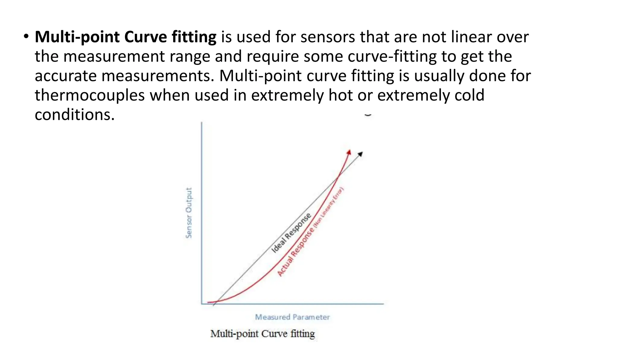
4. • A Sensor is an electronic device that is used to measure some sort of
physical parameters (e.g. temperature, pressure, light intensity, etc).
The output of an electronic sensor is an electrical signal that is
either analog or digital.
• Processing the sensor’s output can be done in hardware (using
discrete electronic elements) or in software (using some sort of
microcontrollers or MPUs).
7. • Humidity Sensors
• Strain gauges
• Photo Optic Sensors
• Flow and Level Switches
• These categories can all be split further into subcategories for
example, within position sensors there are the following types;
9. Sensor Calibration
• Sensors are electronic devices. They are sensitive to the changes in
their working environment. Undesirable and sudden changes in the
working environments of the sensors give undesired output values.
Thus, the expected output differs from the measured output. This
comparison between the Expected output and measured output is
called Sensor Calibration.
10. Standard Reference Method
• Here the sensor output is compared with a standard physical
reference to know the error in some sensors. Examples of sensor
calibration are rulers and meter sticks, For temperature sensors-
Boiling water at 100C,
11. Calibration Methods
• There are three standard calibration methods used for sensors. They
are-
• One point calibration.
• Two-point calibration.
• Multi-Point Curve Fitting.
12. Some of the terms used with the characteristic
curve are-
• Offset – This value tells us whether the sensor output is higher or
lower than the ideal linear response.
• Sensitivity or Slope – This gives the rate of change of sensor output. A
difference in slope shows that the sensor output changes at a
different rate than the ideal response.
• Linearity – Not all sensors have a linear characteristic curve over the
given measurement range.
13. One point calibration is used to correct the sensor
offset errors when accurate measurement of only
a single level is required and the sensor is linear.
Temperature sensors are usually one point
calibrated
• .
14. • Two-point calibration is used to correct both slope and off-set errors.
This calibration is used in the cases when the sensor we know that
the sensor output is reasonably linear over a measurement range.
Here two reference values are needed- reference High, reference Low.
15. • Multi-point Curve fitting is used for sensors that are not linear over
the measurement range and require some curve-fitting to get the
accurate measurements. Multi-point curve fitting is usually done for
thermocouples when used in extremely hot or extremely cold
conditions.
16. Sensor output signal types
Analog Signals
• Voltage Output: Many sensors generate a continuous voltage signal proportional
to the measured physical quantity. The voltage can vary within a specific range,
representing the changes in the sensed parameter.
• Current Output: Some sensors provide a continuous current output that varies in
response to changes in the measured parameter.
• Resistance Output: Certain sensors, especially those based on resistive elements,
produce a change in resistance that corresponds to the variation in the physical
quantity being measured.
• Analog signals are characterized by their continuous and smooth variations, and
they are often used in applications where a high level of precision is required.
17. Digital Signals:
• Digital Voltage Levels: Modern sensors, especially those interfacing with digital
systems, convert their measurements into digital signals. Digital signals consist of
discrete voltage levels, typically represented as binary code (0s and 1s).
• Digital Communication Protocols: Some sensors communicate their data using
standardized digital communication protocols such as I2C (Inter-Integrated
Circuit), SPI (Serial Peripheral Interface), or UART (Universal Asynchronous
Receiver-Transmitter).
• Digital signals are often preferred for their robustness against noise, ease of
integration with microcontrollers and digital systems, and the ability to transmit
data over longer distances without significant signal degradation.
18. Pulse Signals
• Frequency/Pulse Output:
Some sensors generate output signals in the form of pulses or
frequency variations. The frequency or pulse rate is proportional to the
measured parameter.
• PWM (Pulse Width Modulation): In PWM, the width of pulses in a train is
modulated based on the sensed quantity. The duty cycle represents the
magnitude of the measured parameter.
• Pulse signals are commonly used in applications where a frequency or
pulse count is a more convenient way to convey information.
19. Serial Communication:
• UART (Universal Asynchronous Receiver-Transmitter): Sensors may
use UART for serial communication, providing a stream of data with
start and stop bits.
• I2C (Inter-Integrated Circuit) and SPI (Serial Peripheral Interface):
Sensors interfacing with microcontrollers or other devices may use
I2C or SPI for communication.