Dp24742745
•
0 likes•229 views

IJERA (International journal of Engineering Research and Applications) is International online, ... peer reviewed journal. For more detail or submit your article, please visit www.ijera.com

Recommended
More Related Content
Viewers also liked
Viewers also liked (20)
Similar to Dp24742745
Similar to Dp24742745 (20)
Dp24742745
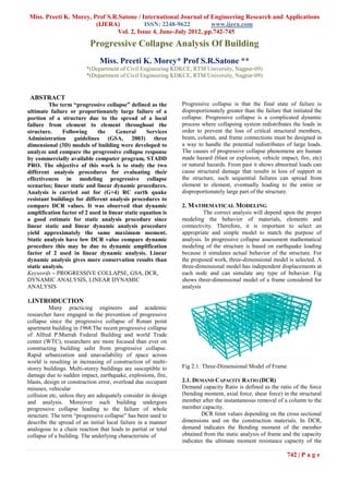
- 1. Miss. Preeti K. Morey, Prof S.R.Satone / International Journal of Engineering Research and Applications (IJERA) ISSN: 2248-9622 www.ijera.com Vol. 2, Issue 4, June-July 2012, pp.742-745 Progressive Collapse Analysis Of Building Miss. Preeti K. Morey* Prof S.R.Satone ** *(Department of Civil Engineering KDKCE, RTM University, Nagpur-09) *(Department of Civil Engineering KDKCE, RTM University, Nagpur-09) ABSTRACT The term “progressive collapse” defined as the Progressive collapse is that the final state of failure is ultimate failure or proportionately large failure of a disproportionately greater than the failure that initiated the portion of a structure due to the spread of a local collapse. Progressive collapse is a complicated dynamic failure from element to element throughout the process where collapsing system redistributes the loads in structure. Following the General Services order to prevent the loss of critical structural members, Administration guidelines (GSA, 2003) three beam, column, and frame connections must be designed in dimensional (3D) models of building were developed to a way to handle the potential redistributes of large loads. analyze and compare the progressive collapse response The causes of progressive collapse phenomena are human by commercially available computer program, STADD made hazard (blast or explosion, vehicle impact, fire, etc) PRO. The objective of this work is to study the two or natural hazards. From past it shows abnormal loads can different analysis procedures for evaluating their cause structural damage that results in loss of support in effectiveness in modeling progressive collapse the structure, such sequential failures can spread from scenarios; linear static and linear dynamic procedures. element to element, eventually leading to the entire or Analysis is carried out for (G+4) RC earth quake disproportionately large part of the structure. resistant buildings for different analysis procedures to compare DCR values. It was observed that dynamic 2. MATHEMATICAL MODELING amplification factor of 2 used in linear static equation is The correct analysis will depend upon the proper a good estimate for static analysis procedure since modeling the behavior of materials, elements and linear static and linear dynamic analysis procedure connectivity. Therefore, it is important to select an yield approximately the same maximum moment. appropriate and simple model to match the purpose of Static analysis have low DCR value compare dynamic analysis. In progressive collapse assessment mathematical procedure this may be due to dynamic amplification modeling of the structure is based on earthquake loading factor of 2 used in linear dynamic analysis. Linear because it simulates actual behavior of the structure. For dynamic analysis gives more conservation results than the proposed work, three-dimensional model is selected. A static analysis. three-dimensional model has independent displacements at Keywords – PROGRESSIVE COLLAPSE, GSA, DCR, each node and can simulate any type of behavior. Fig DYNAMIC ANALYSIS, LINEAR DYNAMIC shows three-dimensional model of a frame considered for ANALYSIS analysis 1.INTRODUCTION Many practicing engineers and academic researcher have engaged in the prevention of progressive collapse since the progressive collapse of Ronan point apartment building in 1968.The recent progressive collapse of Alfred P.Murrah Federal Building and world Trade center (WTC), researchers are more focused than ever on constructing building safer from progressive collapse. Rapid urbanization and unavailability of space across world is resulting in increasing of construction of multi- storey buildings. Multi-storey buildings are susceptible to Fig 2.1: Three-Dimensional Model of Frame damage due to sudden impact, earthquake, explosions, fire, blasts, design or construction error, overload due occupant 2.1. DEMAND CAPACITY RATIO (DCR) misuses, vehicular Demand capacity Ratio is defined as the ratio of the force collision etc, unless they are adequately consider in design (bending moment, axial force, shear force) in the structural and analysis. Moreover such building undergoes member after the instantaneous removal of a column to the progressive collapse leading to the failure of whole member capacity. structure. The term “progressive collapse” has been used to DCR limit values depending on the cross sectional describe the spread of an initial local failure in a manner dimensions and on the construction materials. In DCR, analogous to a chain reaction that leads to partial or total demand indicates the Bending moment of the member collapse of a building. The underlying characteristic of obtained from the static analysis of frame and the capacity indicates the ultimate moment resistance capacity of the 742 | P a g e
- 2. Miss. Preeti K. Morey, Prof S.R.Satone / International Journal of Engineering Research and Applications (IJERA) ISSN: 2248-9622 www.ijera.com Vol. 2, Issue 4, June-July 2012, pp.742-745 member i.e. Plastic Moment. DCRs are not used to C10 37 70 0 38 29 78 determine the acceptability of component behavior, but it C11 1 78 87 1 24 42 is used only to determine the structure’s regularity of the building. DCRs for building components are calculated by C12 0 75 35 0 13 57 following Eq. C13 0 11 74 0 10 90 DCR= Mmax / Mp 6 52 51 6 49 56 C19 Mmax: Bending Moment of the member obtained from the analysis C20 0 60 25 0 33 78 Mp: Expected ultimate moment capacity of the member. C21 0 42 64 0 0 42 (Mp=0.138Fckbd2) 0 14 82 0 12 49 C22 The acceptance criteria for DCR are given below For typical structure (symmetrical structure) = DCR≤ 2.0 C28 19 59 68 16 28 55 For typical structure (unsymmetrical structure) = DCR≤ C29 3 63 93 3 32 44 1.5 C30 0 48 79 0 1 66 C31 0 15 67 1 11 36 Table 3.2- CASE-II: After removing C3 column most affected column Static Case Seismic Case Column Difference Difference No Fy Mx Mz Fy Mx Mz C1 6 31 55 4 6 41 C2 30 76 92 30 13 72 C3 - - - - - - C4 26 72 100 27 10 86 Fig 2.2: Three-Dimensional Model of Case-I C5 3 29 91 2 6 30 C10 0 59 4 0 26 35 C11 1 75 66 1 13 87 C12 26 81 7 28 19 36 C13 1 70 4 1 11 86 C19 0 40 10 0 6 58 C20 0 49 17 0 35 15 C21 3 72 15 3 45 31 C22 0 43 6 0 24 10 C28 1 40 6 2 24 73 C29 3 53 4 3 34 22 C30 10 67 3 11 41 20 Fig 2.3: Three-Dimensional Model of Case-I C31 2 50 1 2 23 19 3. PERFORMANCE ANALYSIS Table 3.3: Result of column wise DCR of Linear Static Table 3.1- CASE-I : After removing C1 column most analysis and linear dynamic analysis affected column Static Case Seismic Case Col STATIC DCR SEISMIC DCR um values No n Case -I Case –II Case -I Case -II Column Difference Difference No C1 X 0.41 X 0.92 C2 0.54 0.47 1.41 1.24 Fy Mx Mz Fy Mx Mz C3 0.36 X 1.35 X C1 - - - - - - C4 0.14 0.45 1.25 1.54 C2 29 79 93 30 23 72 C5 0.17 0.24 1.17 1.24 C3 4 32 94 3 0 79 C6 0.35 0.36 1.57 1.62 C4 0 12 100 1 10 85 C7 0.36 0.35 1.75 1.80 743 | P a g e
- 3. Miss. Preeti K. Morey, Prof S.R.Satone / International Journal of Engineering Research and Applications (IJERA) ISSN: 2248-9622 www.ijera.com Vol. 2, Issue 4, June-July 2012, pp.742-745 C8 0.11 0.11 1.78 1.69 Case II C9 0.35 0.31 1.18 1.13 C10 0.76 0.093 1.38 0.73 C11 0.52 0.46 1.30 1.15 C12 0.070 0.77 1.11 1.58 C13 0.14 0.44 1.16 1.44 C14 0.16 0.22 1.06 1.12 C15 0.061 0.096 1.29 1.32 C16 0.078 0.048 1.44 1.49 C17 0.13 0.13 1.57 1.49 C18 0.15 0.19 1.09 1.100 Figure 3.2: Column wise DCR of case-II C19 0.41 0.33 0.48 0.90 C20 0.29 0.22 0.67 0.65 4. CONCLUSION C21 0.26 0.53 1.29 0.70 Dynamic analysis procedures for progressve collapse C22 0.099 0.20 1.12 0.97 determinations, if modeled using initial conditions C23 0.50 0.57 1.62 1.69 methodology, are simple to perforrme by practicing engineers through computer programs. C24 0.35 0.37 1.70 1.75 The dynamic amplification factor of 2 used in equation is C25 0.47 0.46 1.98 1.98 a good estimate for static analysis procedres . Since linear C26 0.13 0.19 1.20 1.21 static and linear dynamic analysis procedures yield C27 0.27 0.23 1.18 1.13 approximately the same maximum deflection. C28 0.75 0.18 1.38 0.76 Case II of LDA i.e.RC Frame with removal of column has highest DCR value in comparison with LDAcase and other C29 0.31 0.25 0.74 0.72 LSA case.Results indicated that DCRof column is 1.98 C30 0.12 0.75 0.90 0.53 which is less than 2 i.e. GSA criteria.Hence the frame is C31 0.094 0.22 1.21 1.05 less vulnerable to progressive collapse. C32 0.37 0.29 1.42 1.39 C33 0.24 0.23 1.53 1.56 4. REFERENCES ACI (2002), Building Code requirements for Structural C34 0.42 0.42 1.89 1.95 Concrete (ACI 318-02), American Concrete Institute, C35 0.135 0.168 1.27 1.31 Farmington Hills, Michigan. C36 0.24 0.28 1.103 1.11 ASCE (2002), Minimum Design Loads for Buildings and A. Comparison of Linear Static DCR And Linear Other Structures (SEI/ASCE 7-02), American Society of Dynamic DCR Civil Engineers, Washington, DC. Case I GSA (2000), Facilities Standards for the Public Buildings Service, P100-2000, General Services Administration. GSA (2003a), Facilities Standards for the Public Buildings Service, P100-2003, General Services Administration. GSA (2003b), Progressive Collapse Analysis and Design Guidelines for New Federal Office Buildings and Major Modernization Projects, General Services Administration IS 1893 (Part 1): Criteria for Earthquake Resistant Design of Structures. Nair, R. S., Preventing Disproportionate Collapse. Journal Fig 3.1: Column wise DCR of case-I of Performance of Constructed Facilities ASCE, 20 (4), 2006, pp. 309-314. Luccioni, B.M., Ambrosini, R.D., Danesi, R.F. (2003). "Analysis of building collapse under blast loads." Engineering Structures 26 (2004) 63-71. 744 | P a g e
- 4. Miss. Preeti K. Morey, Prof S.R.Satone / International Journal of Engineering Research and Applications (IJERA) ISSN: 2248-9622 www.ijera.com Vol. 2, Issue 4, June-July 2012, pp.742-745 Karim, Mohammed R.; Michelle S. Hoo Fatt "Impact of the Boeing 767 Aircraft into the World Trade Center",(October 2005, pp.28-63). Hiroshi Akiyama,”Collapse Modes of Structures under Strong Motion of Earthquake” Annals of GeophysicsVol.45, December 2002, pp16-19 David N. Bilow and Kamara,PhD, “U.S. General Services Administration Progressive Collapse Design Guidelines Applied to Concrete Moment-Resisting Frame Building ASCE Structures Congress Nashville, Tennessee, May18-22 2004 , pp.29-34 H. S. Lew “simple analytical approaches for evaluating progressive collapse potential of low and mid-rise buildings that could be used in routine design by design professionals”. (2005). Remennikov, A.M. (2003). A Review of Methods forPredicting Bomb Blast Effects on Buildings. Journal of Battlefield Technology, 2003, 6(3) 5-10. Argos Press Pty Ltd. Steven M. Baldridge and Francis K. Humay, ” a study illustrates the inherent ability of seismically designed RC beam-column frames to resist progressive collapse”. (2003) 745 | P a g e