The document summarizes key functions and components of a mixing console:
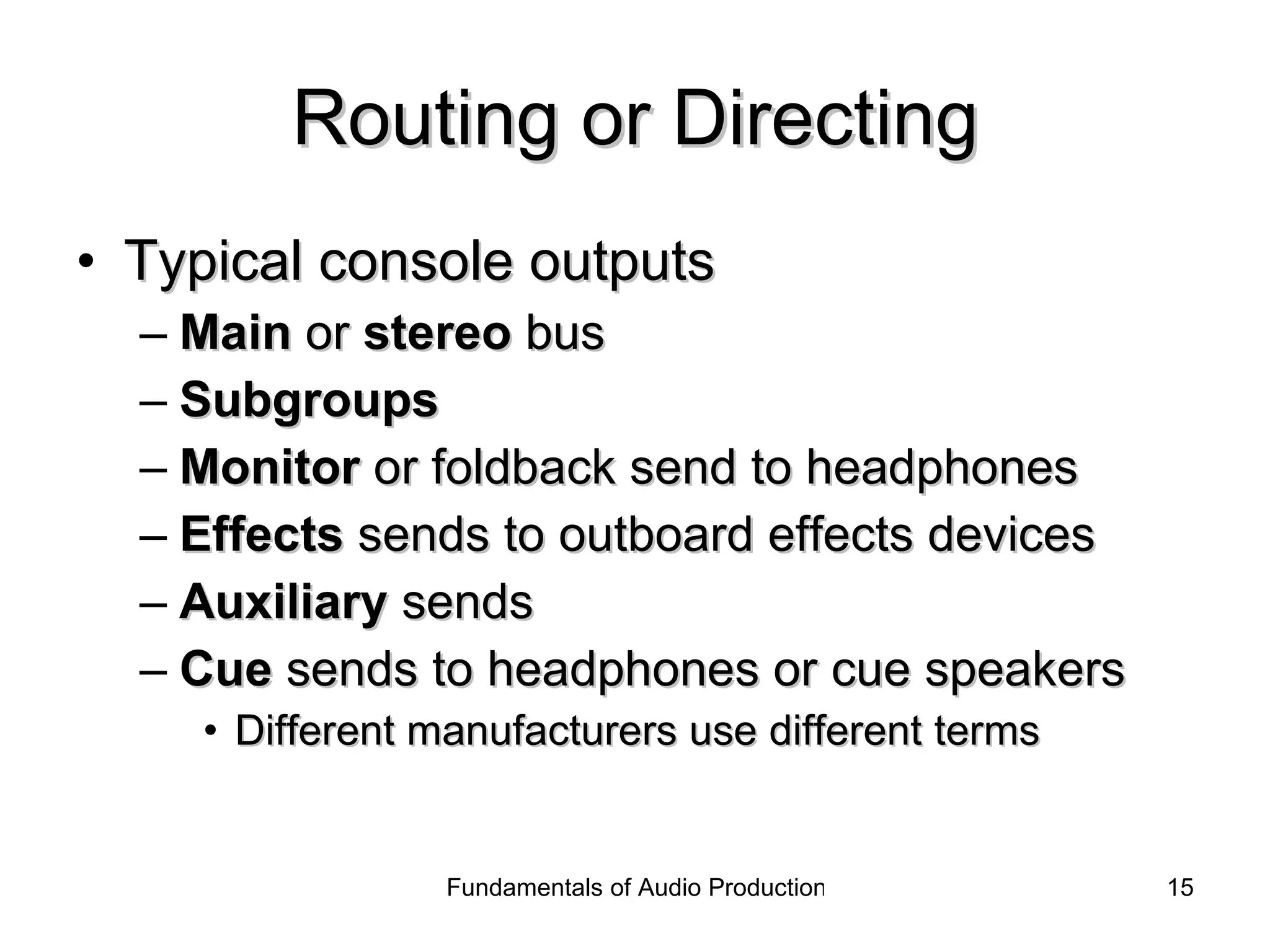
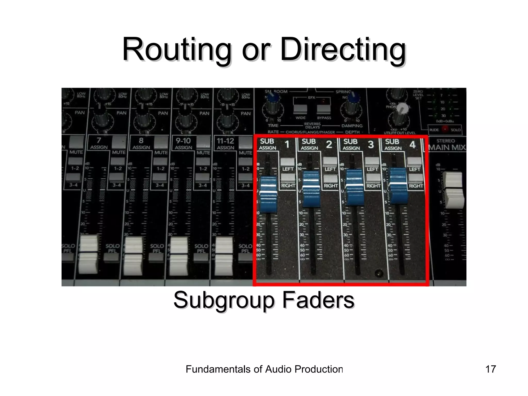
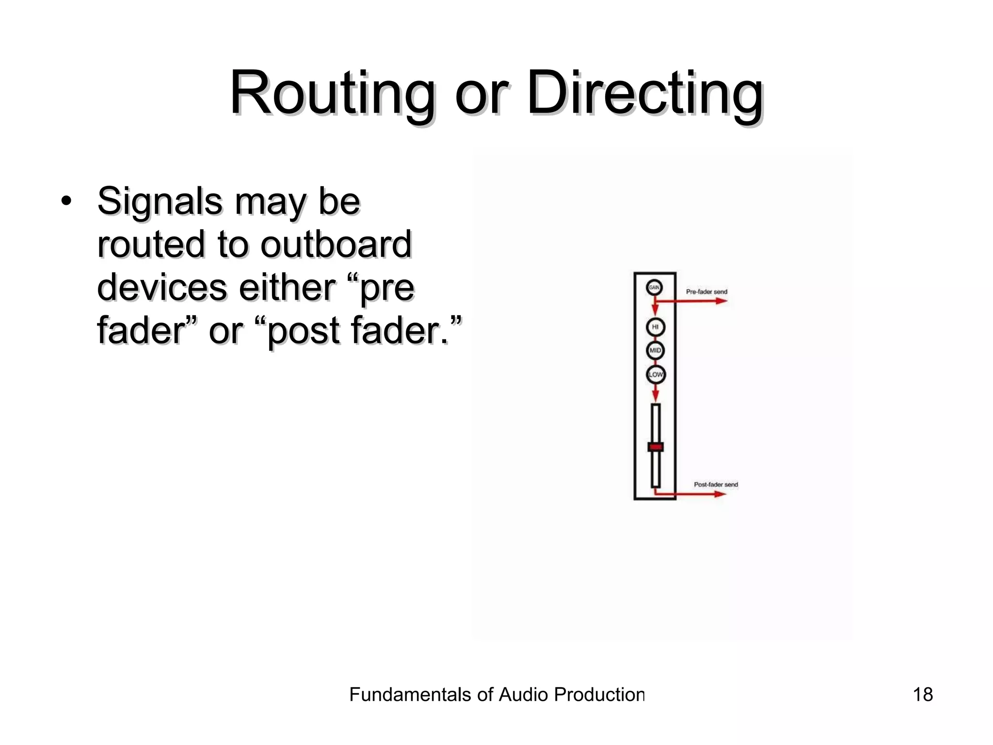
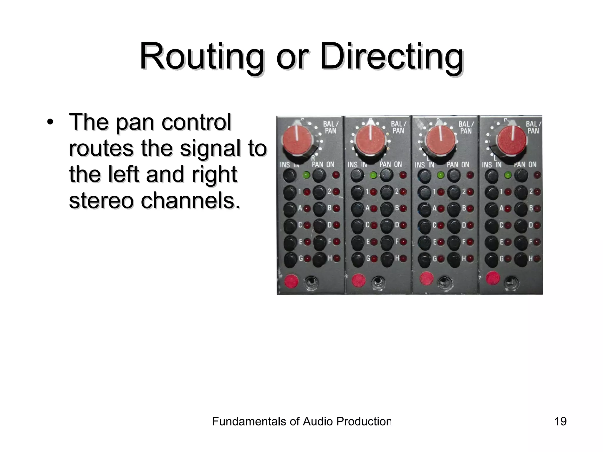
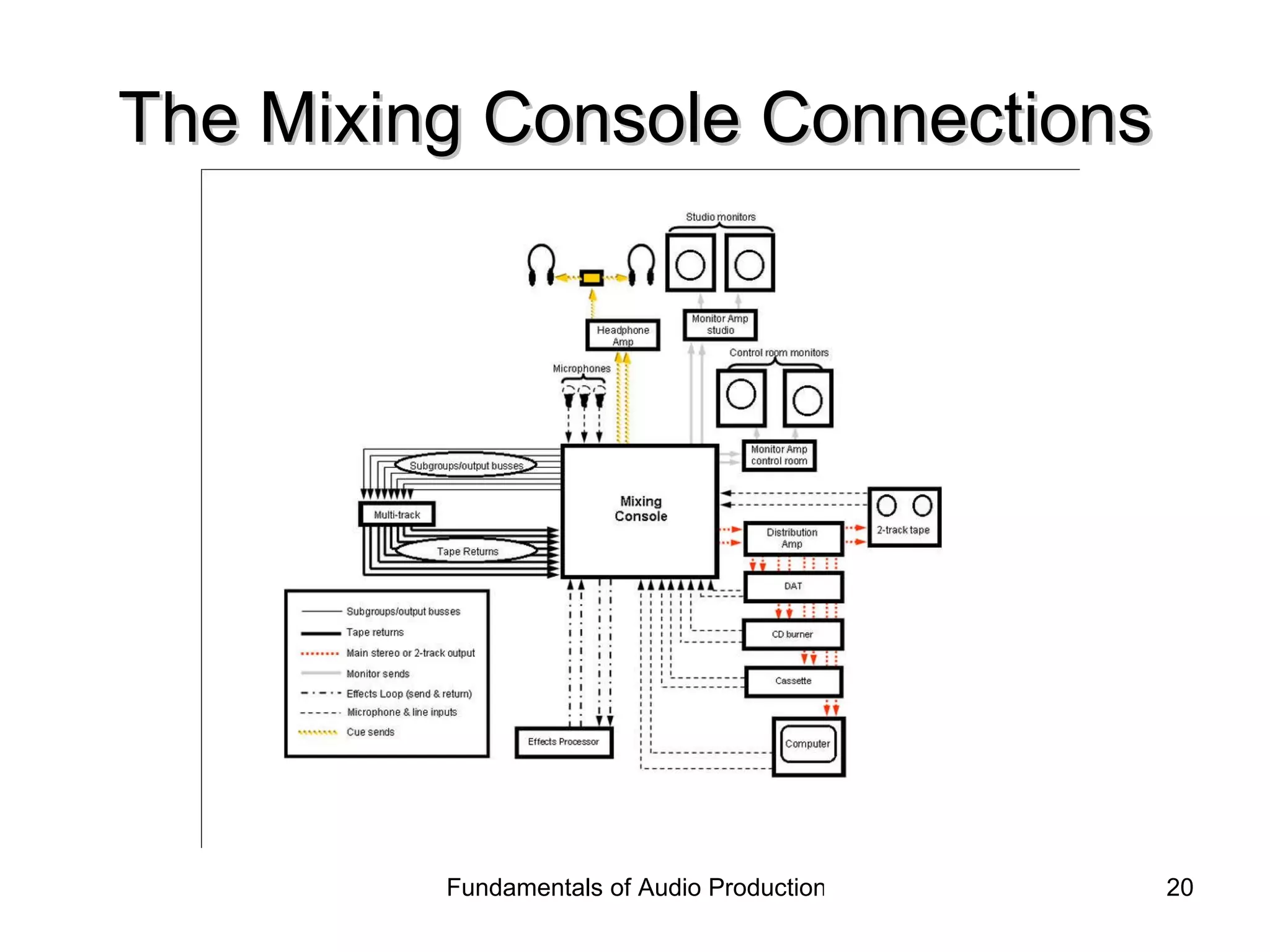
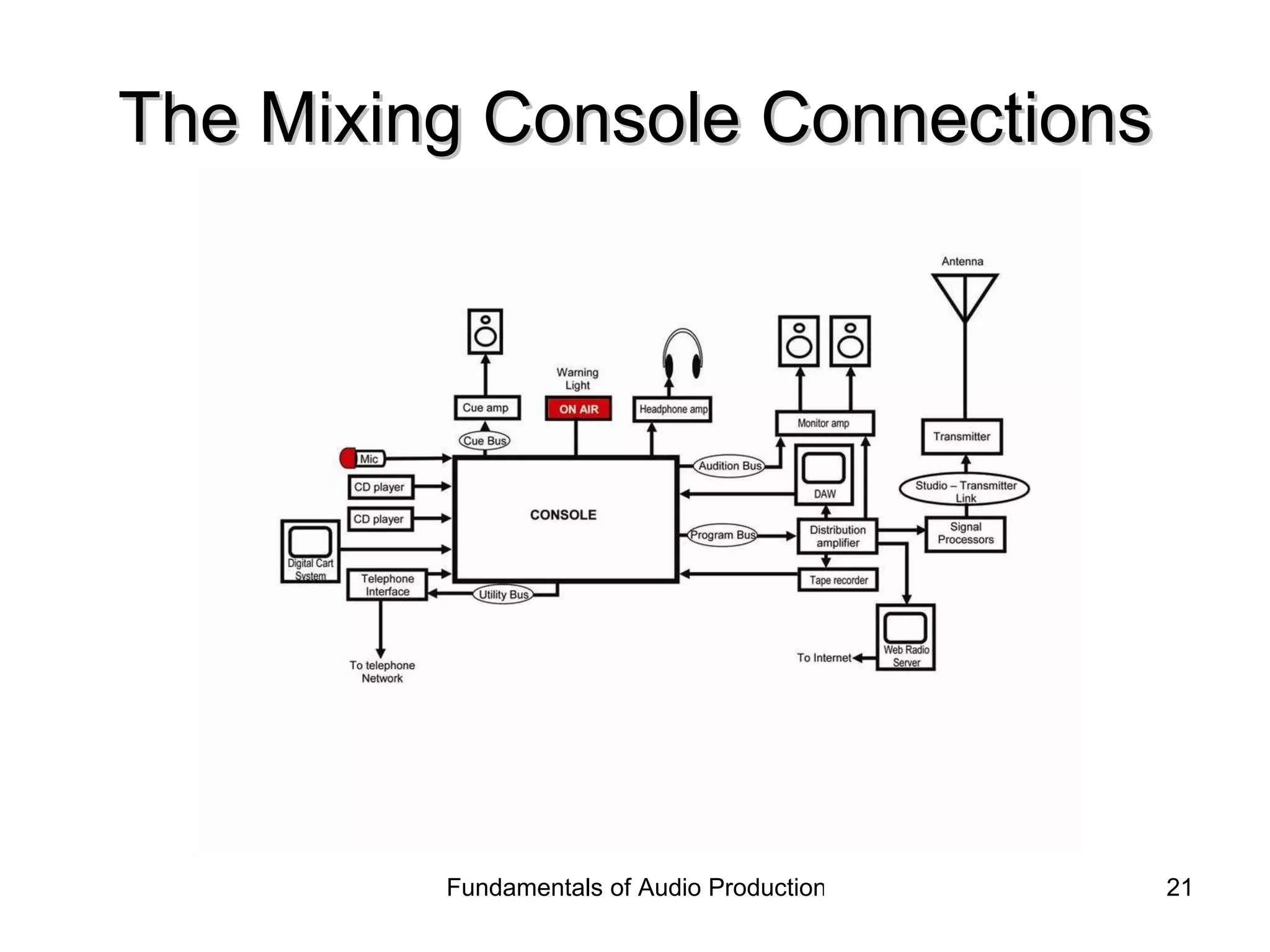
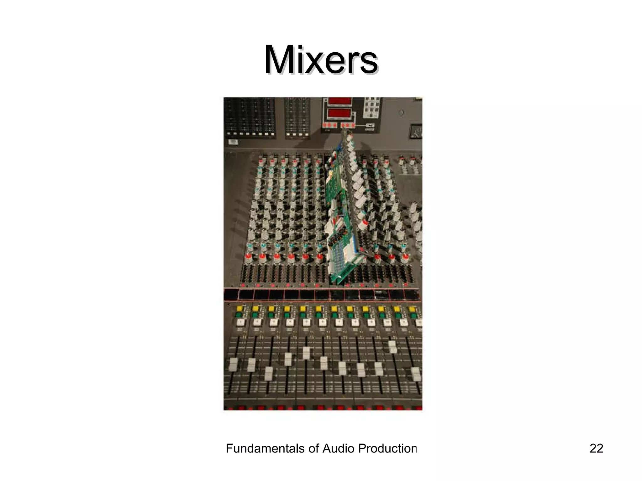
1) A mixing console has three main functions - amplification, mixing, and routing. It amplifies audio signals, allows adjustment of signal levels during mixing, and routes signals to different destinations using buses.
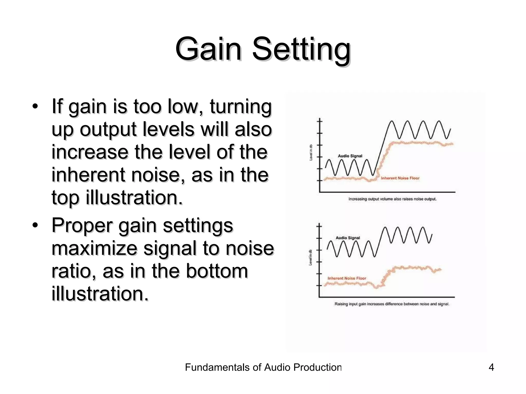
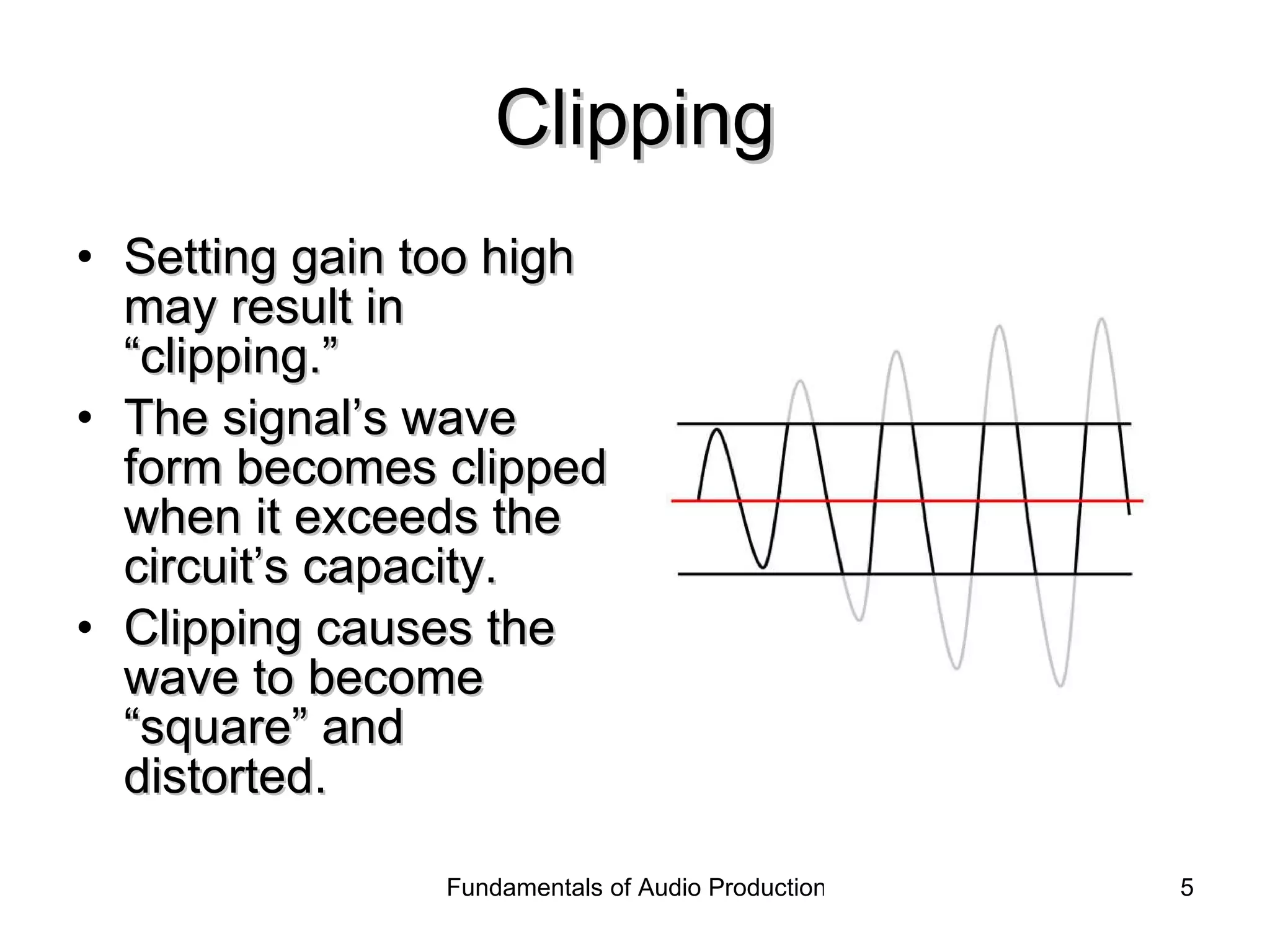
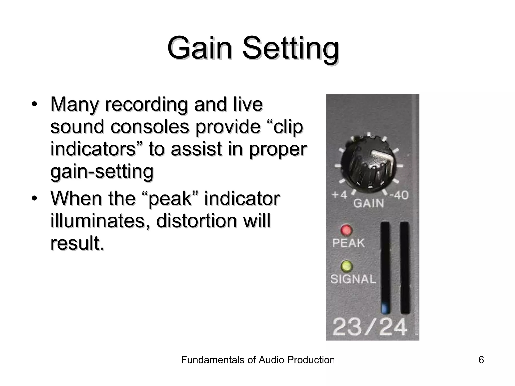
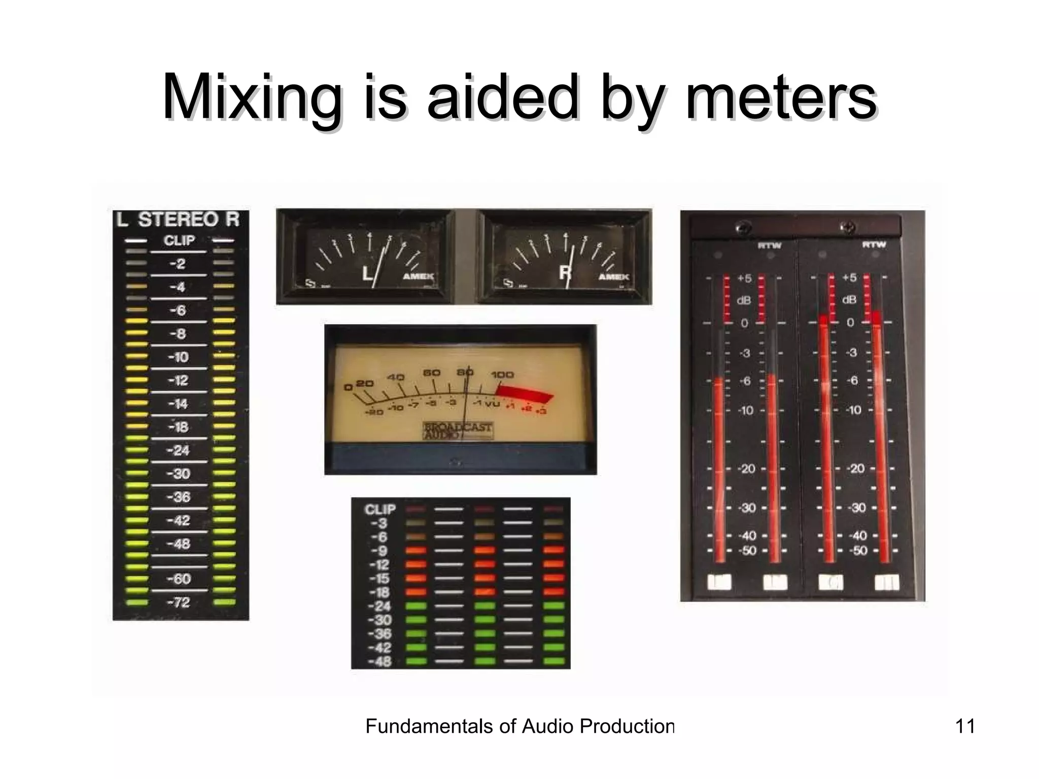
2) Proper gain setting is important for clear audio - too low results in noise, too high causes distortion. Clip indicators help monitor levels and prevent distortion.
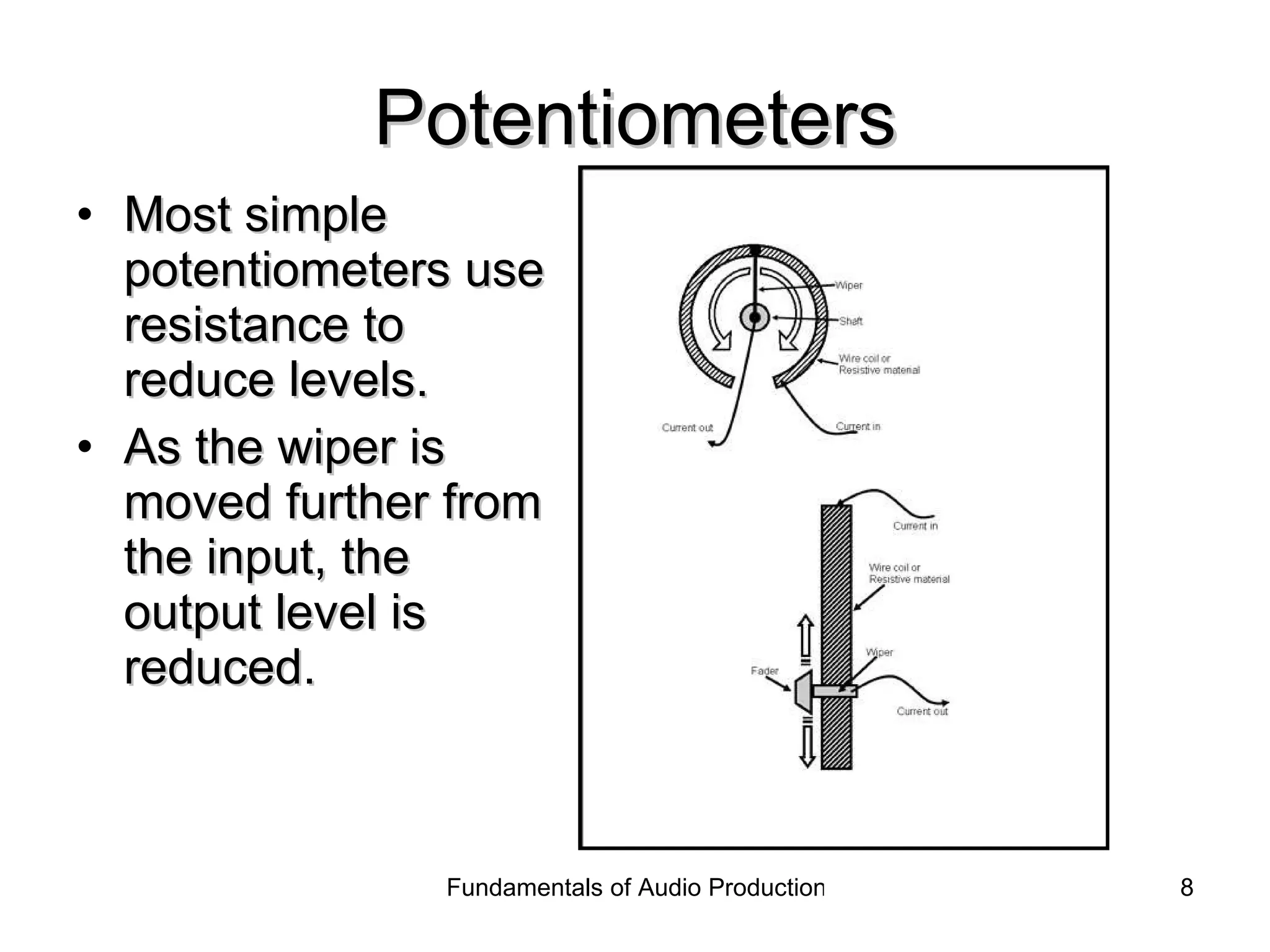
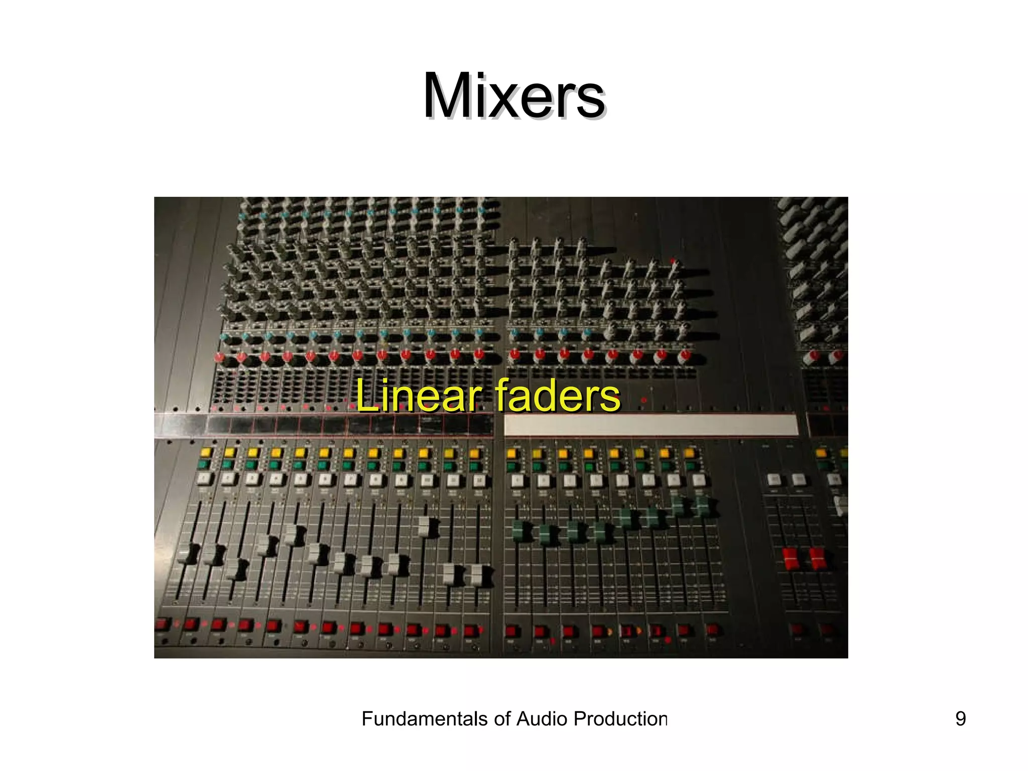
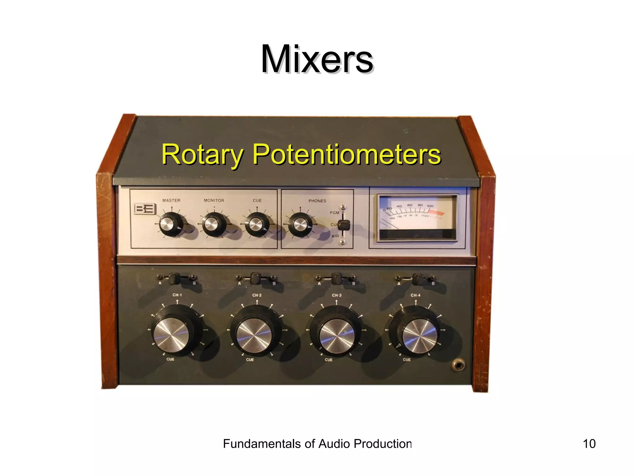
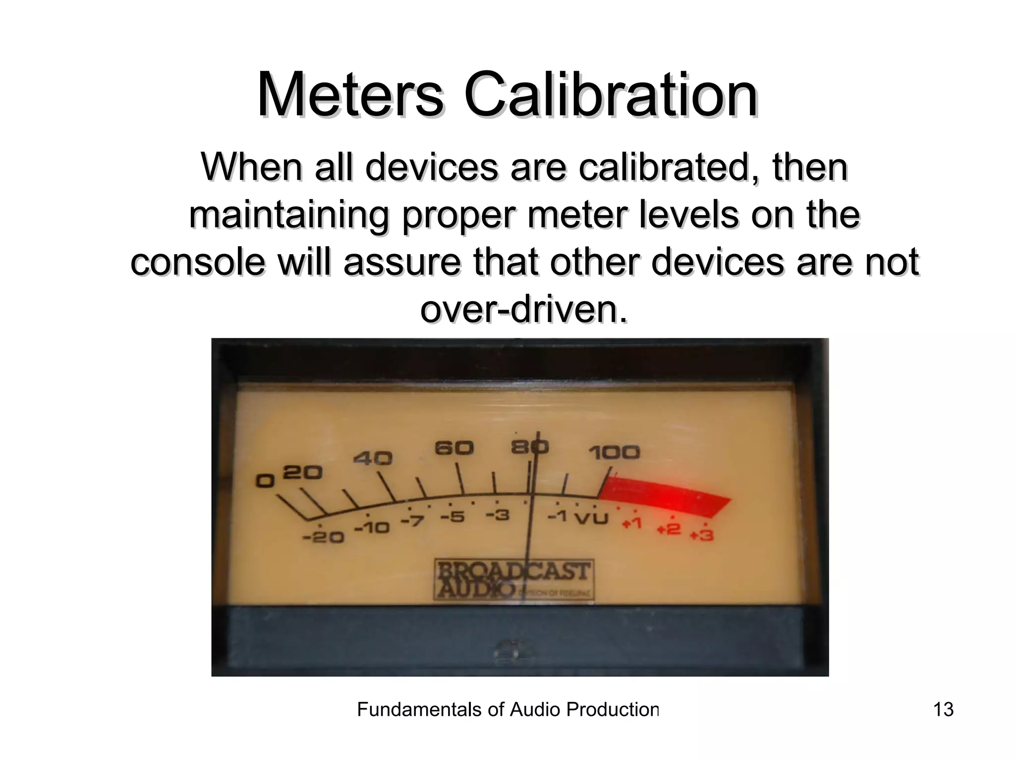
3) Mixing involves adjusting relative signal levels using faders or potentiometers to cut or reduce levels. Meters help calibrate and monitor levels across the recording chain.