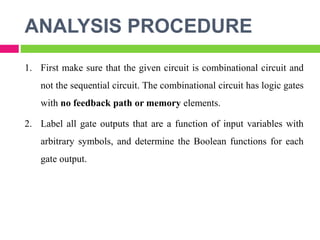
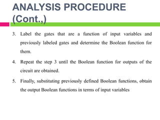
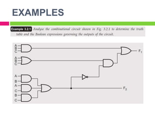
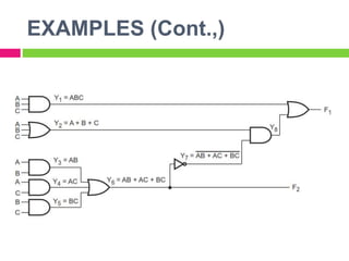
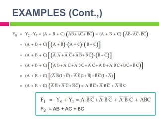
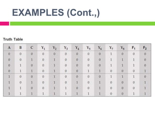
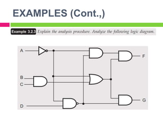
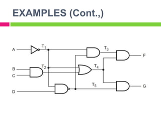
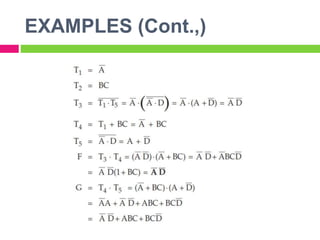
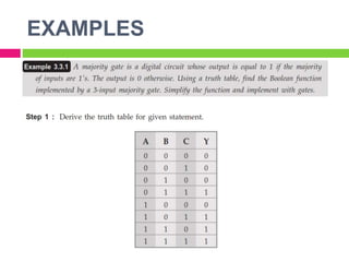
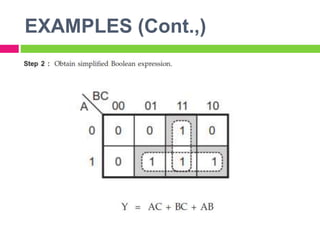
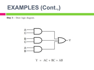
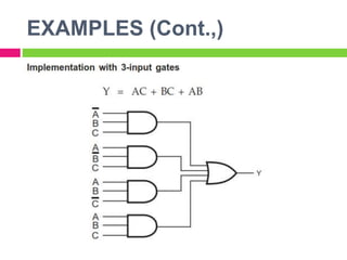
CS8351
DIGITAL PRINCIPLES
AND SYSTEM DESIGN
BY
E. VINOTH, AP/ECE
MOOKAMBIGAI COLLEGE OF ENGINEERING
UNIT 2
COMBINATIONAL LOGIC
INTRODUCTION
 When logic gates are connected together to produce a specified
output for certain specified combinations of input variables, with no
storage involved, the resulting circuit is called combinational logic
circuit.
 In combinational logic circuit, the output variables are at all times
dependent on the combination of input variables.
ANALYSIS PROCEDURE
1. First make sure that the given circuit is combinational circuit and
not the sequential circuit. The combinational circuit has logic gates
with no feedback path or memory elements.
2. Label all gate outputs that are a function of input variables with
arbitrary symbols, and determine the Boolean functions for each
gate output.
ANALYSIS PROCEDURE
(Cont.,)
3. Label the gates that are a function of input variables and
previously labeled gates and determine the Boolean function for
them.
4. Repeat the step 3 until the Boolean function for outputs of the
circuit are obtained.
5. Finally, substituting previously defined Boolean functions, obtain
the output Boolean functions in terms of input variables
EXAMPLES
EXAMPLES (Cont.,)
EXAMPLES (Cont.,)
EXAMPLES (Cont.,)
EXAMPLES (Cont.,)
EXAMPLES (Cont.,)
EXAMPLES (Cont.,)
DESIGN PROCEDURE
1. The problem definition.
2. The determination of number of available input variables and
required output variables.
3. Assigning letter symbols to input and output variables.
4. The derivation of truth table indicating the relationships between
input and output variables.
5. Obtain simplified Boolean expression for each output.
6. Obtain the logic diagram.
EXAMPLES
EXAMPLES (Cont.,)
EXAMPLES (Cont.,)
EXAMPLES (Cont.,)
THANK YOU

Digital Principles and system design Combination Circuits

  • 1.
    CS8351 DIGITAL PRINCIPLES AND SYSTEMDESIGN BY E. VINOTH, AP/ECE MOOKAMBIGAI COLLEGE OF ENGINEERING
  • 2.
  • 3.
    INTRODUCTION  When logicgates are connected together to produce a specified output for certain specified combinations of input variables, with no storage involved, the resulting circuit is called combinational logic circuit.  In combinational logic circuit, the output variables are at all times dependent on the combination of input variables.
  • 4.
    ANALYSIS PROCEDURE 1. Firstmake sure that the given circuit is combinational circuit and not the sequential circuit. The combinational circuit has logic gates with no feedback path or memory elements. 2. Label all gate outputs that are a function of input variables with arbitrary symbols, and determine the Boolean functions for each gate output.
  • 5.
    ANALYSIS PROCEDURE (Cont.,) 3. Labelthe gates that are a function of input variables and previously labeled gates and determine the Boolean function for them. 4. Repeat the step 3 until the Boolean function for outputs of the circuit are obtained. 5. Finally, substituting previously defined Boolean functions, obtain the output Boolean functions in terms of input variables
  • 6.
  • 7.
  • 8.
  • 9.
  • 10.
  • 11.
  • 12.
  • 13.
    DESIGN PROCEDURE 1. Theproblem definition. 2. The determination of number of available input variables and required output variables. 3. Assigning letter symbols to input and output variables. 4. The derivation of truth table indicating the relationships between input and output variables. 5. Obtain simplified Boolean expression for each output. 6. Obtain the logic diagram.
  • 14.
  • 15.
  • 16.
  • 17.
  • 18.