
Recommended
More Related Content
Similar to Wiring Diagram Calisto T1
Similar to Wiring Diagram Calisto T1 (20)
Recently uploaded
Recently uploaded (20)
Wiring Diagram Calisto T1
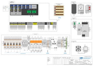
- 1. In Service In Service In Service In Service In Service In Service Set 1 / Tap 2 S R Set 1 / Tap 3 S R Set 2 / Tap 1 S R Set 2 / Tap 2 S R Set 2 / Tap 3 S R Set 1 / Tap 1 S R Relay Outputs RL1 STATUS RL2 INFO RL3 WARNING RL4 ACTION V1-A V1-B V2-A V2-B V3-A V3-B 23 25 29 RELAYS NETWORK SWITCH HYGRO STAT T1 FAN 5 6 7 6.66VA 3.33VA 3 4 8V - 4V - 50/60 Hz 230v 12V - 10VA SYNC LAMP SOCKET PSU SYNC 7 11 S R SET 1 S R S R TAP 1 2 3 S R SET 2 S R S R TAP 1 2 3 VOLTAGE INPUT V1 A B V2 A B V3 A B RELAY STATUS INFO WARNING ACTION DANGER INPUT + 24V DC SYNC A B MAX 15VAC 7 8 6 5 4 A B C HFCT LINK SET 2 RS485-1 GND D- D+ RS485-2 GND D- D+ PD INPUTS Calisto T1 Bottom View RS 485-1 RS 485-2 NOTE 1: In order to monitor Partial Discharge on Bushing Set 2, coax jumpers are required from: A to 4 B to 5 C to 6 Jumper Bar Jumper Bar 221 222 223 224 225 226 227 228 229 231 232 233 234 235 236 237 238 239 221 222 223 224 225 226 227 228 229 231 232 233 234 235 236 237 238 239 52 53 54 55 56 57 52 53 54 55 56 57 D+ 40 40 41 41 402 403 404 405 402 403 404 405 301 302 301 302 5 6 6 5 15 13 3 1 N 2 N 401 45 23 17 24 12 18 16 17 18 7 12 ANALOG/DIGITAL IO SLOTS LOCATION: FRONT PANEL OF T1 1 2 3 4 L N HEATER SOCKET HYGROSTAT 43 42 46 45 42 44 13 14 7 H1 H2 H3 X1 X2 X3 V1 V0 V2 V0 V3 V0 D- GND D+ D- GND CCVT Metering PT D+ D- G RS485 D+ D- G RS485 DRY CONTACT TO CONTROL ROOM INFO DRY CONTACT TO CONTROL ROOM STATUS N L CUSTOMER CONNECTIONS CUSTOMER CONNECTIONS ENCLOSURE DOOR INSIDE 406 11 12 14 A1 A2 21 22 24 11 12 14 A1 A2 21 22 24 11 12 14 A1 A2 21 22 24 11 12 14 A1 A2 21 22 24 0 V DC L N L F1 F12 F11 F10 F13 F28 F24 F27 F21 5 Jumper Bar 44 4 HEATER 43 F14 LIGHT TOWER 11 Jumper Bar 401 46 30 32 31 SPARE F25 F29 F33 +24 V DC OPTIONAL LIGHT TOWER 24VDC 30 DRY CONTACT TO CONTROL ROOM WARNING DRY CONTACT TO CONTROL ROOM ACTION OPTIONAL LIGHT TOWER STATUS OPTIONAL LIGHT TOWER INFO OPTIONAL LIGHT TOWER WARNING OPTIONAL LIGHT TOWER ACTION F51 F52 F53 51 52 53 87 88 89 86 31 32 ENCLOSURE BOTTOM LEFT N L + + DC 24V 24 VDC POWER SUPPLY 11 12 4 3 8 ENCLOSURE TOP RIGHT FAN PSU OPTIONAL NETWORK SWITCH OPTIONAL NETWORK SWITCH (TOP VIEW) 1 2 23 24 CUSTOMER CONNECTIONS 14 L N + - DC HEATER 6 6 CUSTOMER CONNECTIONS Bushing Set 1 Bushing Set 2 Terminal strip 120/240 VAC POWER AND MAIN GROUND 8 3 TO GROUND BAR N L 3.2 um Doble Engineering Company Marlborough, MA 01752 TITLE: Wiring Diagram, Calisto T1 DOBLE PART NO.: 76X-0065-01 ENGINEERING REFERENCE: 051-02-04-07 REVISION: A DO NOT SCALE DRAWING SCALE: None SHEET OF 3 1 MATERIAL: FINISH: ALL COMPONETS MUST COIMPLY WITH 72X-0455-01 WEIGHT (KG): All Parts:- 1. Debur all sharp edges 2. Label with Doble part Number and revision 3. Dimensions are after finishing unless stated otherwise All dimensions are in: mm 1 inch = 25.40 mm Tolerances, unless otherwise specified: Decimal X +/-0.5 X.X +/-0.10 X.XX +/-0.02 X.XXX +/-0.005 Angular +/-0.5 Surface This document and all its contents are the sole and exclusive property of Doble Engineering Company. Unauthorised copying, use, and/or distribution of this document or any portion thereof is hereby expressly prohibited. REV ECN Description of Change Created By. APP DATE NOTES: Printing notes:- A1 size Full Colour Folded to A4 80 gsm A Released into Omnify MF n/a n/a IS4-EDOC-16 Rev. C Drawing design to be printed at A1 size PK 2021-06-16 22545
- 2. F10 F11 F12 F14 F18 F1 L N 5 6 3 4 AC POWER L N See SYNC HYGROTHERM 5 2 HEATER LAMP L N CONVENIENCE OUTLET L N POWER SUPPLY L N 43 15 13 3 4 14 16 44 2 1 5 7 11 Incoming AC Supply 100v AC – 240v AC Max. Amps Required 10 Amp 181-1003 AC Power PSU 120 W 24v DC F28 23 +24v DC 0V DC N L E + + - - F25 F24 F27 F21 F33 F29 25 29 DC POWER 8 Ground/Earth See AC Power 5 3 4 31 32 30 LED Tower +24v DC Option Relays RL4/11 Fan 86 87 F10 + - Calisto T1 Hygrotherm 1 2 + - Network Switch RL4, A1 2, 4, 6, 8 See System Alert – Dry Contacts Connector Part No. Connector Discription Max. Conductor Size 220-2675 2 Way connector 12 AWG/2.5 mm2 Pin 1 = +24VDC Pin 2 = 0VDC Description Location Part No. Fuse, 3.15A, 5x20mm, Antisurge All, unless specified 384-0281 Fuse, 315mA, 5x20mm, Antisurge F51, F52, F53 384-0307 Fuse Table 406 23 45 17 11 12 24 46 18 401 DC Power 8 3 6 7 12 Network Switch Convenience Outlet Calisto T1 To Ground Bar Power Supply Transformer/Site Ground Ground lug outside of the enclosure, bottom rear. 1 Ground bar to enclosure door 2 Ground bar to enclosure lug. Ground lug outside of the enclosure, bottom rear. Ground/Earth Connections R S R S R S R S R S R S Bushing Sensor 1 Bushing Sensor 2 Bushing Sensor 3 Bushing Sensor 4 Bushing Sensor 5 Bushing Sensor 6 Set1 Tap1 Set1 Tap2 Set1 Tap3 Set2 Tap1 Set2 Tap2 Set2 Tap3 Tap 1 S Tap 1 R Tap 1 221 222 223 224 225 226 227 228 229 Tap 2 S Tap 2 R Tap 2 Tap 3 S Tap 3 R Tap 3 Set 1 Tap 1 S Tap 1 R Tap 1 239 238 237 236 235 234 233 232 231 Tap 2 S Tap 2 R Tap 2 Tap 3 S Tap 3 R Tap 3 Pin 1 – SET 1 TAP 1 S Pin 2 – SET 1 TAP 1 R Pin 3 – SET 1 TAP 1 Pin 4 – SET 1 TAP 2 S Pin 5 – SET 1 TAP 2 R Pin 6 – SET 1 TAP 2 Pin 7 – SET 1 TAP 3 S Pin 8 – SET 1 TAP 3 R Pin 9 – SET 1 TAP 3 To Device Device ID Connector Part No. Connector Description Max. Conductor Size Calisto T1 BUSHING INPUT SET 220-2676 9 Way connector 12 AWG/2.5mm2 Pin 1 – SET 2 TAP 1 S Pin 2 – SET 2 TAP 1 R Pin 3 – SET 2 TAP 1 Pin 4 – SET 2 TAP 2 S Pin 5 – SET 2 TAP 2 R Pin 6 – SET 2 TAP 2 Pin 7 – SET 2 TAP 3 S Pin 8 – SET 2 TAP 3 R Pin 9 – SET 2 TAP 3 To Device Device ID Connector Part No. Connector Description Max. Conductor Size Calisto T1 BUSHING INPUT SET 220-2676 9 Way connector 12 AWG/2.5mm2 Set 2 Bushing Inputs Voltage Inputs System Alerts - Dry Contacts 52 53 54 55 56 57 L N L N L N A B A B A B V1 V2 V3 F51 51 F52 52 F53 53 Description Location Part No. Fuse, 3.15A, 5x20mm, Antisurge All, unless specified 384-0281 Fuse, 315mA, 5x20mm, Antisurge F51, F52, F53 384-0307 Fuse Table To Device Device ID Connector Part No. Calisto T1 Voltage 220-2677 ! ! ! ! To Device Device ID Connector Part No. Connector Description Max. Conductor Size doblePrime Voltage 220-2677 6 Way connector 12 AWG/2.5mm2 Pin 1 – V1, A Pin 2 – V1, B Pin 3 – V2, A Pin 4 – V2, B Pin 5 – V3, A Pin 6 – V3, B ! ! ! ! 21 22 24 11 12 14 A1 A2 RL1 21 22 24 11 12 14 A1 A2 RL2 21 22 24 11 12 14 A1 A2 RL3 21 22 24 11 12 14 A1 A2 RL4 Alert Status to Control Room Alert Status to Control Room Alert Status to Control Room Alert Status to Control Room LED Tower Status LED Tower Info LED Tower Warning LED Tower Action DC- DC- DC- DC- 220-2654 Jumper B 30 29 See DC Power 220-2654 Jumper 406 29 401 F28 See DC Power 401 401 401 401 405 404 403 402 405 404 403 402 Pin1 Pin2 Pin3 Pin4 Pin5 Pin6 Pin7 Pin8 05X-0048 ALERT: Status ALERT: Info ALERT: Warning ALERT: Action Alert Status Status Alert Status Info Alert Status Warning Alert Status Action To Device Device ID Connector Part No. Calisto T1 Relay 220-2786 Pin 1 - STATUS Pin 2 - STATUS Pin 3 - INFO Pin 4 - INFO Pin 5 - WARNING Pin 7 - ACTION Pin 8 - ACTION Pin 6 - WARNING To Device Device ID Connector Part No. Connector Description Max. Conductor Size doblePrime Relay 220-2786 8 Way connector 12 AWG/2.5mm2 3.2 um Doble Engineering Company Marlborough, MA 01752 TITLE: Wiring Diagram, Calisto T1 DOBLE PART NO.: 76X-0065-01 ENGINEERING REFERENCE: 051-02-04-07 REVISION: A DO NOT SCALE DRAWING SCALE: None SHEET OF 3 2 MATERIAL: FINISH: ALL COMPONETS MUST COIMPLY WITH 72X-0455-01 WEIGHT (KG): All Parts:- 1. Debur all sharp edges 2. Label with Doble part Number and revision 3. Dimensions are after finishing unless stated otherwise All dimensions are in: mm 1 inch = 25.40 mm Tolerances, unless otherwise specified: Decimal X +/-0.5 X.X +/-0.10 X.XX +/-0.02 X.XXX +/-0.005 Angular +/-0.5 Surface This document and all its contents are the sole and exclusive property of Doble Engineering Company. Unauthorised copying, use, and/or distribution of this document or any portion thereof is hereby expressly prohibited. REV ECN Description of Change Created By. APP DATE NOTES: Printing notes:- A1 size Full Colour Folded to A4 80 gsm A Released into Omnify MF n/a n/a IS4-EDOC-16 Rev. C Drawing design to be printed at A1 size PK 2021-06-16 22545
- 3. Hygrotherm Heater One Fan 1 2 3 4 5 DC Power 25 F27 AC Power 5 F14 23 F33 DC Power 1 2 3 4 86 87 88 89 + - N L + - DC HEATER DC 45 46 44 42 43 31 32 Climate Control D+ D- GND D+ D- GND White Green Black 62 64 66 White Green Black 61 63 65 White Green Black D+ D- GND White Green Black D+ D- GND 40 41 Twisted Triple Twisted Triple To Device Device ID Connector Part No. Connector Description Max. Conductor Size Calisto T1 RS485 220-2437 3 Way connector 12 AWG/2.5mm2 Pin 1 = GND Pin 2 = D- Pin 3 – D+ To Device Device ID Connector Part No. Calisto T1 RS485 220-2437 To Device Device ID Connector Part No. Calisto T1 RS485 220-2437 RS485 L N AC Power 6 F12 LAMP Lighting 15 16 3.2 um Doble Engineering Company Marlborough, MA 01752 TITLE: Wiring Diagram, Calisto T1 DOBLE PART NO.: 76X-0065-01 ENGINEERING REFERENCE: 051-02-04-07 REVISION: A DO NOT SCALE DRAWING SCALE: None SHEET OF 3 3 MATERIAL: FINISH: ALL COMPONETS MUST COIMPLY WITH 72X-0455-01 WEIGHT (KG): All Parts:- 1. Debur all sharp edges 2. Label with Doble part Number and revision 3. Dimensions are after finishing unless stated otherwise All dimensions are in: mm 1 inch = 25.40 mm Tolerances, unless otherwise specified: Decimal X +/-0.5 X.X +/-0.10 X.XX +/-0.02 X.XXX +/-0.005 Angular +/-0.5 Surface This document and all its contents are the sole and exclusive property of Doble Engineering Company. Unauthorised copying, use, and/or distribution of this document or any portion thereof is hereby expressly prohibited. REV ECN Description of Change Created By. APP DATE NOTES: Printing notes:- A1 size Full Colour Folded to A4 80 gsm A Released into Omnify MF n/a n/a IS4-EDOC-16 Rev. C Drawing design to be printed at A1 size PK 2021-06-16 22545