
Recommended
More Related Content
Similar to 169822126-Liebherr-712-752 (1) - Copie[300-393] XX.pdf
Similar to 169822126-Liebherr-712-752 (1) - Copie[300-393] XX.pdf (20)
Recently uploaded
Recently uploaded (20)
169822126-Liebherr-712-752 (1) - Copie[300-393] XX.pdf
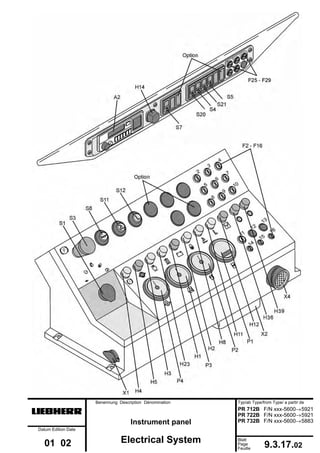
- 1. Benennung Description Dénomination Typ/ab Type/from Type/ a partir de Mjfcifss! Instrument panel PR 712B F/N xxx-5600→5921 PR 722B F/N xxx-5600→5921 PR 732B F/N xxx-5600→5883 Datum Edition Date 01 02 Electrical System Blatt Page Feuille 9.3.17.02
- 3. Benennung Description Dénomination Typ/ab Type/from Type/ a partir de Mjfcifss! Parts list - Instrument panel PR 712B F/N xxx-5922→6199 PR 722B F/N xxx-5922→6199 PR 732B F/N xxx-5884→ Datum Edition Date 01 03 Electrical System Blatt Page Feuille 9.3.18.01 Notes
- 4. pos. description A2 (option) radio / speakers A8 diode combination (V1 - V5) E7 dome light F2 fuses on instrument panel ↓ (application - see listing 9.2. Parts list to Electrical schematic F16 F25 fuses on control panel - cab ↓ (application - see listing 9.2. Parts list to Electrical schematic F29 H1 indicator light - charge indicator red H2 indicator light - glow plug system yellow H3 indicator light - air filter yellow H4 indicator light - parking brake yellow H5 indicator light - repl. oil pressure red H8 indicator light - float position yellow H11 indicator light - reduced travel speed range yellow H12 indicator light - electronic fault indicator red H14 warning light - cab activated by B2 /B3 /B6 red H23 indicator light - hydr. filter monitoring (tank) yellow H36 indicator light - oil level - travel gear - cone seal area left red H39 indicator light - oil level - travel gear - cone seal area right red K2 relay - starter cut off K3 relay - power guard K4 relay - power supply K5 relay - reduced travel speed range indicator light K6 relay - electronic fault indicator K7 step relay - float position K8 relay - power guard K10 relay - warning light K14 relay - glow plug system K17 relay - working light K27 relay - shut off solenoid (Diesel engine) only at PR732B MP ground connection P1 hour meter P2 fuel gauge P3 coolant temperature gauge P4 engine oil pressure gauge S1 starter switch w. preheat position S3 emergency off switch S4 rocker switch - windshield wiper and washer system front S5 rocker switch - windshield wiper and washer system rear S7 rocker switch - working light, instrument lights S8 push button switch - horn S11 push button switch - float position S20 rocker switch - windshield wiper and washer system left door S21 rocker switch - windshield wiper and washer system right door U1 (option) transformer - radio V1-5 diode combination A8 V1 diode 1A for K1 V3 diode 1A for K2 V4 diode 1A for H5 V5 diode 1A free X1 electrical outlet 24V X2 panel plug - central wiring harness 72 pole X4 panel plug - cab wiring harness 14 pole X5 serial connecting terminal (ground signal to K10, machine identification) X37-1 plug to U1,K10 X37-2 plug to F28, E7, F26, F25 X38 plug to M3 X39 plug to M2 X40 plug to M4 X41 plug to M5 X42 plug to E3,E4,E5,E6 X46 plug to M7,M13 X47 plug to U1, A2 components are named in the panel components in panel refer to illustrated configuration, valid only for basic equipment set-up
- 5. Benennung Description Dénomination Typ/ab Type/from Type/ a partir de Mjfcifss! Instrument panel PR 712B F/N xxx-5922→6199 PR 722B F/N xxx-5922→6199 PR 732B F/N xxx-5884→ Datum Edition Date 01 03 Electrical System Blatt Page Feuille 9.3.18.02
- 7. Benennung Description Dénomination Typ/ab Type/from Type/ a partir de Mjfcifss! Parts list - instrument panel PR 712 B F/N xxx-6200→ PR 722 B F/N xxx-6200→ Datum Edition Date 01 03 Electrical system Blatt Page Feuille 9.3.19.01 Notes
- 8. pos. description A2 (option) radio / speakers A8 diode combination (V1 - V5) E7 dome light F2 fuses on instrument panel ↓ (application - see listing on page 9.2.19.00) F16 F25 fuses on control panel - cab ↓ (application - see listing on page 9.2.19.00) F29 H1 indicator light - charge indicator red H2 indicator light - glow plug system yellow H3 indicator light - air filter yellow H4 indicator light - parking brake yellow H5 indicator light - repl. oil pressure red H8 indicator light - float position yellow H11 indicator light - reduced travel speed range yellow H12 indicator light - electronic fault indicator red H14 warning light - cab activated by B2 /B3 /B6 red H23 indicator light - hydr. filter monitoring (tank) yellow H36 indicator light - oil level - travel gear - cone seal area left red H39 indicator light - oil level - travel gear - cone seal area right red K2 relay - starter cut off K3 relay - power guard K4 relay - power supply K5 relay - reduced travel speed range indicator light K6 relay - electronic fault indicator K7 step relay - float position K10 relay - warning light K17 relay - working light K24 relay - interval timer K27 relay - shut off solenoid (Diesel engine) K39 relay - power guard K49 relay - interval switch on K50 relay - interval switch front K51 relay - interval switch left door K52 relay - interval switch right door K53 relay - glow plug system MP ground connection P1 hour meter P2 fuel gauge P3 coolant temperature gauge P4 engine oil pressure gauge S1 starter switch w. preheat position S3 emergency off switch S4 rocker switch - windshield wiper front S5 rocker switch - windshield wiper rear S7 rocker switch - working light, instrument lights S8 push button switch - horn S11 push button switch - float position S20 rocker switch - windshield wiper left door S21 rocker switch - windshield wiper right door S35 rocker switch - preselection interval switch / washer system U1 (option) transformer - radio V1-5 diode combination A8 V1 diode 1A for K1 V3 diode 1A for K2 V4 diode 1A for H5 V5 diode 1A free X1 electrical outlet 24V X2 panel plug - central wiring harness 72 pole X4 panel plug - cab wiring harness 14 pole X5 serial connecting terminal (ground signal to K10, machine identification) X37-1 plug to U1,K10 X37-2 plug to F28, E7, F26, F25 X38 plug to M3 X39 plug to M2 X40 plug to M4 X41 plug to M5 X42 plug to E3,E4,E5,E6 X46 plug to M7,M13 X47 plug to U1 X97 electrical outlet 12V X98 plug to X97, X99 X99 plug to A2 components are named in the panel components in panel refer to illustrated configuration, valid only for basic equipment set-up
- 9. Benennung Description Dénomination Typ/ab Type/from Type/ a partir de Mjfcifss! Instrument panel PR 712 B F/N xxx-6200→ PR 722 B F/N xxx-6200→ Datum Edition Date 01 03 Electrical system Blatt Page Feuille 9.3.19.02
- 11. Benennung Description Dénomination Typ/ab Type/from Type/ a partir de Mjfcifss! Parts list - Instrument panel PR 742 B F/N xxx-5600→6199 Datum Edition Date 01 03 Electrical System Blatt Page Feuille 9.3.40.01 Notes
- 12. pos. description A2 (option) radio / speakers A8 diode combination (V1 - V5) E7 dome light F2 fuses on instrument panel ↓ (application - see listing on page 9.2.40.00) F16 F25 fuses on control panel - cab ↓ (application - see listing on page 9.2.40.00) F29 H1 indicator light - charge indicator red H2 indicator light - glow plug system yellow H3 indicator light - air filter yellow H4 indicator light - parking brake yellow H5 indicator light - repl. oil pressure red H8 indicator light - float position yellow H11 indicator light - reduced travel speed range yellow H12 indicator light - electronic fault indicator red H14 warning light - cab activated by B2 /B3 /B6 red H16 indicator light - hydr. filter monitoring (tank) yellow H25 indicator light - oil level - travel gear - cone seal area left red H26 indicator light - oil level - travel gear - cone seal area right red K2 relay - starter cut off K3 relay - power guard K4 relay - power supply K7 step relay - float position K8 relay - power guard K10 relay - warning light K14 relay - glow plug system K15 relay - reduced travel speed range indicator light K16 relay - electronic fault indicator K17 relay - working light K27 relay - shut off solenoid (Diesel engine) MP ground connection P1 hour meter P2 fuel gauge P3 coolant temperature gauge P4 engine oil pressure gauge S1 starter switch w. preheat position S3 emergency off switch S4 rocker switch - windshield wiper and washer system front S5 rocker switch - windshield wiper and washer system rear S7 rocker switch - working light, instrument lights S8 push button switch - horn S11 push button switch - float position S20 rocker switch - windshield wiper and washer system left door S21 rocker switch - windshield wiper and washer system right door U1 (option) transformer - radio V1-5 diode combination A8 V1 diode 1A for K1 V3 diode 1A for K2 V4 diode 1A for H5 V5 diode 1A free X1 electrical outlet 24V X2 panel plug - central wiring harness 72 pole X4 panel plug - cab wiring harness 14 pole X5 serial connecting terminal (ground signal to K10, machine identification) X37-1 plug to U1,K10 X37-2 plug to F28, E7, F26, F25 X38 plug to M3 X39 plug to M2 X40 plug to M4 X41 plug to M5 X42 plug to E3,E4,E5,E6 X46 plug to M7,M13 X47 plug to U1, A2 components are named in the panel components in panel refer to illustrated configuration, valid only for basic equipment set-up
- 13. Benennung Description Dénomination Typ/ab Type/from Type/ a partir de Mjfcifss! Instrument panel PR 742 B F/N xxx-5600→6199 Datum Edition Date 01 03 Electrical System Blatt Page Feuille 9.3.40.02
- 15. Benennung Description Dénomination Typ/ab Type/from Type/ a partir de Mjfcifss! Parts list - Instrument panel PR 742 B F/N xxx-6200→ Datum Edition Date 01 03 Electrical System Blatt Page Feuille 9.3.41.01 Notes
- 16. pos. description A2 (option) radio / speakers A8 diode combination (V1 - V5) A9 diode combination (V15-V16) E7 dome light F2 fuses on instrument panel ↓ (application - see listing on page 9.2.41.00) F16 F25 fuses on control panel - cab ↓ (application - see listing on page 9.2.41.00) F29 H1 indicator light - charge indicator red H2 indicator light - glow plug system yellow H3 indicator light - air filter yellow H4 indicator light - parking brake yellow H5 indicator light - repl. oil pressure red H8 indicator light - float position yellow H11 indicator light - reduced travel speed range yellow H12 indicator light - electronic fault indicator red H14 warning light - cab activated by B2 /B3 /B6 red H16 indicator light - hydr. filter monitoring (tank) yellow H25 indicator light - oil level - travel gear - cone seal area left red H26 indicator light - oil level - travel gear - cone seal area right red K2 relay - starter cut off K3 relay - power guard K4 relay - power supply K7 step relay - float position K8 relay - power guard K10 relay - warning light K14 relay - glow plug system K15 relay - reduced travel speed range indicator light K16 relay - electronic fault indicator K17 relay - working light K24 relay - interval timer K27 relay - shut off solenoid (Diesel engine) K49 relay - interval switch on K50 relay - interval switch front K51 relay - interval switch left door K52 relay - interval switch right door MP ground connection P1 hour meter P2 fuel gauge P3 coolant temperature gauge P4 engine oil pressure gauge S1 starter switch w. preheat position S3 emergency off switch S4 rocker switch - windshield wiper front S5 rocker switch - windshield wiper rear S7 rocker switch - working light, instrument lights S8 push button switch - horn S11 push button switch - float position S20 rocker switch - windshield wiper left door S21 rocker switch - windshield wiper right door S35 rocker switch - preselection interval switch / washer system U1 (option) transformer - radio V1-5 diode combination A8 V1 diode 1A for K1 V3 diode 1A for K2 V4 diode 1A for H5 V5 diode 1A free X1 electrical outlet 24V X2 panel plug - central wiring harness 72 pole X4 panel plug - cab wiring harness 14 pole X5 serial connecting terminal (ground signal to K10, machine identification) X37-1 plug to U1,K10 X37-2 plug to F28, E7, F26, F25 X38 plug to M3 X39 plug to M2 X40 plug to M4 X41 plug to M5 X42 plug to E3,E4,E5,E6 X46 plug to M7,M13 X47 plug to U1 X97 electrical outlet 12V X98 plug to X97, X99 X99 plug to A2 components are named in the panel components in panel refer to illustrated configuration, valid only for basic equipment set-up
- 17. Benennung Description Dénomination Typ/ab Type/from Type/ a partir de Mjfcifss! Instrument panel PR 742 B F/N xxx-6200→ Datum Edition Date 01 03 Electrical System Blatt Page Feuille 9.3.41.02
- 19. Notes Typ/ab Type/from Type/a partir de Datum Edition Date 01 01 Blatt Page Feuille Benennung Description Dénomination 9.3.50.01 Parts list - Instrument panel Electrical System Mjfcifss! PR 752 F/N xxx-2002→2026
- 20. pos. description A2 (option) radio / speakers A8 diode combination A13 diode combination E7 dome light F2 fuses on instrument panel ↓ (application - see listing on page 9.2.50.00) F15 F25 fuses on control panel - cab ↓ (application - see listing on page 9.2.50.00) F30 H1 indicator light - charge indicator red H2 indicator light - glow plug system yellow H3 indicator light - air filter yellow H4 indicator light - parking brake yellow H5 indicator light - repl. oil pressure red H8 indicator light - float position yellow H11 indicator light - reduced travel speed range yellow H12 indicator light - electronic fault indicator red H17 warning light - cab activated by B2 /B3 /B6 /B27 red H23 indicator light - hydr. filter monitoring (tank) yellow H35 indicator light - hydraulic oil overheating red K2 relay - starter cut off K3 relay - power guard K4 relay - power supply K5 relay - reduced travel speed range indicator light K6 relay - electronic fault indicator K7 step relay K10 relay - warning light K38 relay - working light K39 relay - power guard K53 time relay - glow plug system K73 relay - shut off solenoid (Diesel engine) (Y49) K75 2. relay - working light LS speakers MP ground connections P1 hour meter P2 fuel gauge P3 coolant temperature gauge P4 engine oil pressure gauge S1 starter switch w. preheat position S3 emergency off switch S4 rocker switch - windshield wiper and washer system front S5 rocker switch - windshield wiper and washer system rear S7 rocker switch - working light, instrument lights S8 push button switch - horn S11 push button switch - float position S12 push button switch - travel speed range selection S17 rocker switch - windshield wiper and washer system left door S18 rocker switch - windshield wiper and washer system right door S52 push button switch - pin puller U1 (option) transformer - radio X1 electrical outlet 24V X2 panel plug - central wiring harness 72 pole X4 panel plug - cab wiring harness 14 pole X5 serial connecting terminal (ground signal to K10) X37-1 plug to U1,K10 X37-2 plug to F28, E7, F26, F25 X38 plug to M3 X39 plug to M2 X40 plug to M4 X41 plug to M5 X42 plug to E3,E4,E5,E6 X46 plug to M7,M13 X47 plug to U1, A2 components are named in the panel components in panel refer to illustrated configuration, valid only for basic equipment set-up
- 21. PR 752 F/N xxx-2002→ 2026 Typ/ab Type/from Type/a partir de Datum Edition Date 01 01 Blatt Page Feuille Benennung Description Dénomination 9.3.50.02 Instrumentenpult Instrument Panel Pupitre Mjfcifss!
- 23. Notes Typ/ab Type/from Type/a partir de Datum Edition Date 01 01 Blatt Page Feuille Benennung Description Dénomination 9.3.51.01 Parts list - Instrument panel Electrical System Mjfcifss! PR 752 F/N xxx-2027→ 2062
- 24. pos. description A2 (option) radio / speakers A8 diode combination A13 diode combination E7 dome light F2 fuses on instrument panel ↓ (application - see listing on page 9.2.51.00) F15 F25 fuses on control panel - cab ↓ (application - see listing on page 9.2.51.00) F30 H1 indicator light - charge indicator red H2 indicator light - glow plug system yellow H3 indicator light - air filter yellow H4 indicator light - parking brake yellow H5 indicator light - repl. oil pressure red H8 indicator light - float position yellow H11 indicator light - reduced travel speed range yellow H12 indicator light - electronic fault indicator red H17 warning light - cab activated by B2 /B3 /B6 /B27 red H23 indicator light - hydr. filter monitoring (tank) yellow H35 indicator light - hydraulic oil overheating red H36 indicator light - oil level - travel gear - cone seal area red mounted from machine PR 752 F/N xxx-2007→ K2 relay - starter cut off K3 relay - power guard K4 relay - power supply K5 relay - reduced travel speed range indicator light K6 relay - electronic fault indicator K7 step relay K10 relay - warning light H17 K38 relay - working light K39 relay - power guard K53 time relay - glow plug system K73 relay - shut off solenoid (Diesel engine) (Y49) K75 2. relay - working light LS speakers MP ground connections P1 hour meter P2 fuel gauge P3 coolant temperature gauge P4 engine oil pressure gauge S1 starter switch w. preheat position S3 emergency off switch S4 rocker switch - windshield wiper and washer system front S5 rocker switch - windshield wiper and washer system rear S7 rocker switch - working light, instrument lights S8 push button switch - horn S11 push button switch - float position S12 push button switch - travel speed range selection S17 rocker switch - windshield wiper and washer system left door S18 rocker switch - windshield wiper and washer system right door S52 push button switch - pin puller U1 (option) transformer - radio X1 electrical outlet 24V X2 panel plug - central wiring harness 72 pole X4 panel plug - cab wiring harness 14 pole X5 serial connecting terminal (ground signal to K10) X37-1 plug to U1,K10 X37-2 plug to F28, E7, F26, F25 X38 plug to M3 X39 plug to M2 X40 plug to M4 X41 plug to M5 X42 plug to E3,E4,E5,E6 X46 plug to M7,M13 X47 plug to U1, A2 components are named in the panel components in panel refer to illustrated configuration, valid only for basic equipment set-up
- 25. PR 752 F/N xxx-2027→ 2062 Typ/ab Type/from Type/a partir de Datum Edition Date 01 01 Blatt Page Feuille Benennung Description Dénomination 9.3.51.02 Instrumentenpult Instrument Panel Pupitre Mjfcifss!
- 27. Benennung Description Dénomination Typ/ab Type/from Type/ a partir de Mjfcifss! Parts list - Instrument panel PR 752 F/N xxx-2063→5071 Datum Edition Date 01 02 Electrical System Blatt Page Feuille 9.3.52.01 Notes
- 28. pos. description A2 (option) radio A6 diode combination A8 diode combination E7 dome light F2 fuses on instrument panel ↓ (application - see listing on page 9.2.52.00) F15 F25 fuses on control panel - cab ↓ (application - see listing on page 9.2.52.00) F30 H1 indicator light - charge indicator red H2 indicator light - glow plug system yellow H3 indicator light - air filter yellow H4 indicator light - parking brake yellow H5 indicator light - repl. oil pressure red H8 indicator light - float position yellow H11 indicator light - reduced travel speed range yellow H12 indicator light - electronic fault indicator red H14 warning light - cab activated by B2 /B3 /B6 /B26 red H16 indicator light - hydr. filter monitoring (tank) yellow H19 indicator light - oil level - travel gear - cone seal area red H20 indicator light - hydraulic oil overheating red K2 relay - starter cut off K3 relay - power guard K4 relay - power supply K7 step relay - float position K8 relay - power guard K10 relay - warning light H14 K14 time relay - glow plug system K15 relay - reduced travel speed range indicator light K16 relay - electronic fault indicator K17 relay - working light K27 relay - shut off solenoid (Diesel engine) K28 2. relay - working light LS (option) speakers MP ground connections P1 hour meter P2 fuel gauge P3 coolant temperature gauge P4 engine oil pressure gauge S1 starter switch w. preheat position S3 emergency off switch S4 rocker switch - windshield wiper and washer system front S5 rocker switch - windshield wiper and washer system rear S7 rocker switch - working light, instrument lights S8 push button switch - horn S11 push button switch - float position S20 rocker switch - windshield wiper and washer system left door S21 rocker switch - windshield wiper and washer system right door S27 push button switch - pin puller U1 (option) transformer - radio X1 electrical outlet 24V X2 panel plug - central wiring harness 72 pole X4 panel plug - cab wiring harness 14 pole X5 serial connecting terminal (ground signal to K10) X37-1 plug to U1,K10 X37-2 plug to F28, E7, F26, F25 X38 plug to M3 X39 plug to M2 X40 plug to M4 X41 plug to M5 X42 plug to E3,E4,E5,E6 X46 plug to M7,M13 X47 plug to U1, A2 components are named in the panel components in panel refer to illustrated configuration, valid only for basic equipment set-up
- 29. Benennung Description Dénomination Typ/ab Type/from Type/ a partir de Mjfcifss! Instrument panel PR 752 F/N xxx-2063→5071 Datum Edition Date 01 02 Electrical System Blatt Page Feuille 9.3.52.02
- 31. Benennung Description Dénomination Typ/ab Type/from Type/ a partir de Mjfcifss! Parts list - Instrument panel PR 752 F/N xxx-5072→5599 Datum Edition Date 01 02 Electrical System Blatt Page Feuille 9.3.53.01 Notes
- 32. pos. description A2 (option) radio A6 diode combination A8 diode combination E7 dome light F2 fuses on instrument panel ↓ (application - see listing on page 9.2.52.00) F15 F25 fuses on control panel - cab ↓ (application - see listing on page 9.2.52.00) F30 H1 indicator light - charge indicator red H2 indicator light - glow plug system yellow H3 indicator light - air filter yellow H4 indicator light - parking brake yellow H5 indicator light - repl. oil pressure red H8 indicator light - float position yellow H11 indicator light - reduced travel speed range yellow H12 indicator light - electronic fault indicator red H14 warning light - cab activated by B2 /B3 /B6 /B26 red H16 indicator light - hydr. filter monitoring (tank) yellow H19 indicator light - oil level - travel gear - cone seal area red H20 indicator light - hydraulic oil overheating red K2 relay - starter cut off K3 relay - power guard K4 relay - power supply K7 step relay - float position K8 relay - power guard K10 relay - warning light H14 K14 time relay - glow plug system K15 relay - reduced travel speed range indicator light K16 relay - electronic fault indicator K17 relay - working light K27 relay - shut off solenoid (Diesel engine) K28 2. relay - working light LS (option) speakers MP ground connections P1 hour meter P2 fuel gauge P3 coolant temperature gauge P4 engine oil pressure gauge S1 starter switch w. preheat position S3 emergency off switch S4 rocker switch - windshield wiper and washer system front S5 rocker switch - windshield wiper and washer system rear S7 rocker switch - working light, instrument lights S8 push button switch - horn S11 push button switch - float position S20 rocker switch - windshield wiper and washer system left door S21 rocker switch - windshield wiper and washer system right door S27 push button switch - pin puller U1 (option) transformer - radio X1 electrical outlet 24V X2 panel plug - central wiring harness 72 pole X4 panel plug - cab wiring harness 14 pole X5 serial connecting terminal (ground signal to K10) X37-1 plug to U1,K10 X37-2 plug to F28, E7, F26, F25 X38 plug to M3 X39 plug to M2 X40 plug to M4 X41 plug to M5 X42 plug to E3,E4,E5,E6 X46 plug to M7,M13 X47 plug to U1, A2 components are named in the panel components in panel refer to illustrated configuration, valid only for basic equipment set-up
- 33. Benennung Description Dénomination Typ/ab Type/from Type/ a partir de Mjfcifss! Instrument panel PR 752 F/N xxx-5072→5599 Datum Edition Date 01 02 Electrical System Blatt Page Feuille 9.3.53.02
- 35. Benennung Description Dénomination Typ/ab Type/from Type/ a partir de Mjfcifss! Parts list - Instrument panel PR 752 F/N xxx-5600→6199 Datum Edition Date 01 03 Electrical System Blatt Page Feuille 9.3.54.01 Notes
- 36. pos. description A2 (option) radio A6 diode combination A8 diode combination E7 dome light F2 fuses on instrument panel ↓ (application - see listing on page 9.2.55.00) F15 F25 fuses on control panel - cab ↓ (application - see listing on page 9.2.55.00) F30 H1 indicator light - charge indicator red H2 indicator light - glow plug system yellow H3 indicator light - air filter yellow H4 indicator light - parking brake yellow H5 indicator light - repl. oil pressure red H7 indicator light - fan drive red H8 indicator light - float position yellow H11 indicator light - reduced travel speed range yellow H12 indicator light - electronic fault indicator red H14 warning light - cab activated by B2 /B3 /B6 /B26 red H16 indicator light - hydr. filter monitoring (tank) yellow H19 indicator light - oil level - travel gear - cone seal area red H20 indicator light - hydraulic oil overheating red K2 relay - starter cut off K3 relay - power guard K4 relay - power supply K7 step relay - float position K8 relay - power guard K10 relay - warning light H14 K14 time relay - glow plug system K15 relay - reduced travel speed range indicator light K16 relay - electronic fault indicator K17 relay - working light K28 2. relay - working light LS (option) speakers MP ground connections P1 hour meter P2 fuel gauge P3 coolant temperature gauge P4 engine oil pressure gauge S1 starter switch w. preheat position S3 emergency off switch S4 rocker switch - windshield wiper and washer system front S5 rocker switch - windshield wiper and washer system rear S7 rocker switch - working light, instrument lights S8 push button switch - horn S11 push button switch - float position S20 rocker switch - windshield wiper and washer system left door S21 rocker switch - windshield wiper and washer system right door S27 push button switch - pin puller U1 (option) transformer - radio X1 electrical outlet 24V X2 panel plug - central wiring harness 72 pole X4 panel plug - cab wiring harness 14 pole X5 serial connecting terminal (ground signal to K10) X37-1 plug to U1,K10 X37-2 plug to F28, E7, F26, F25 X38 plug to M3 X39 plug to M2 X40 plug to M4 X41 plug to M5 X42 plug to E3,E4,E5,E6 X46 plug to M7,M13 X47 plug to U1, A2 components are named in the panel components in panel refer to illustrated configuration, valid only for basic equipment set-up
- 37. Benennung Description Dénomination Typ/ab Type/from Type/ a partir de Mjfcifss! Instrument panel PR 752 F/N xxx-5600→6199 Datum Edition Date 01 03 Electrical System Blatt Page Feuille 9.3.54.02
- 39. Benennung Description Dénomination Typ/ab Type/from Type/ a partir de Mjfcifss! Parts list - Instrument panel PR 752 F/N xxx-6200→ Datum Edition Date 01 03 Electrical System Blatt Page Feuille 9.3.55.01 Notes
- 40. pos. description A2 (option) radio A6 diode combination A8 diode combination A9 diode combination E7 dome light F2 fuses on instrument panel ↓ (application - see listing on page 9.2.56.00) F19 F25 fuses on control panel - cab ↓ (application - see listing on page 9.2.56.00) F29 H1 indicator light - charge indicator red H2 indicator light - glow plug system yellow H3 indicator light - air filter yellow H4 indicator light - parking brake yellow H5 indicator light - repl. oil pressure red H7 indicator light - fan drive red H8 indicator light - float position yellow H11 indicator light - reduced travel speed range yellow H12 indicator light - electronic fault indicator red H14 warning light - cab activated by B2 /B3 /B6 /B26 red H16 indicator light - hydr. filter monitoring (tank) yellow H19 indicator light - oil level - travel gear - cone seal area red H20 indicator light - hydraulic oil overheating red K2 relay - starter cut off K3 relay - power guard K4 relay - power supply K7 step relay - float position K8 relay - power guard K10 relay - warning light H14 K14 time relay - glow plug system K15 relay - reduced travel speed range indicator light K16 relay - electronic fault indicator K17 relay - working light K24 relay - interval timer K28 2. relay - working light K49 relay - interval switch on K50 relay - interval switch front K51 relay - interval switch left door K52 relay - interval switch right door MP ground connections P1 hour meter P2 fuel gauge P3 coolant temperature gauge P4 engine oil pressure gauge S1 starter switch w. preheat position S3 emergency off switch S4 rocker switch - windshield wiper front S5 rocker switch - windshield wiper rear S7 rocker switch - working light, instrument lights S8 push button switch - horn S11 push button switch - float position S20 rocker switch - windshield wiper left door S21 rocker switch - windshield wiper right door S27 push button switch - pin puller S35 rocker switch - preselection interval switch / washer system U1 (option) transformer - radio X1 electrical outlet 24V X2 panel plug - central wiring harness 72 pole X4 panel plug - cab wiring harness 14 pole X5 serial connecting terminal (ground signal to K10) X37-1 plug to U1,K10 X37-2 plug to F28, E7, F26, F25 X38 plug to M3 X39 plug to M2 X40 plug to M4 X41 plug to M5 X42 plug to E3,E4,E5,E6 X46 plug to M7,M13 X47 plug to U1 X97 electrical outlet 12V X98 plug to X97, X99 X99 plug to A2 X100 plug to B52, B53 components are named in the panel components in panel refer to illustrated configuration, valid only for basic equipment set-up
- 41. Benennung Description Dénomination Typ/ab Type/from Type/ a partir de Mjfcifss! Instrument panel PR 752 F/N xxx-6200→ Datum Edition Date 01 03 Electrical System Blatt Page Feuille 9.3.55.02
- 43. Benennung Description Dénomination Typ/ab Type/from Type/ a partir de Mjfcifss! Location of electrical components PR 712 B F/N xxx-0501→ PR 722 B F/N xxx-1001→ PR 732 B F/N xxx-2501→ PR 742 B F/N xxx-2501→ Datum Edition Date 01 01 Electrical System Blatt Page Feuille 9.4.10.01 Notes Note: View of location contains only series components for basic machines
- 44. A1 electronic box B2 temperature sending unit - coolant (96°C) B3 pressure switch - engine oil pressure B4 vacuum indicator - air filter (500 mWs = 50 mbar vacuum) B5 pressure switch - parking brake (12 bar) B6 pressure switch - repl. oil pressure (8 bar) B7 horn B8 (option) pressure switch right - back up alarm / back up light (1,5 bar) B9 (option) pressure switch left - back up alarm / back up light (1,5 bar) B10 (option) horn - back up alarm B11 pressure switch - quick drop (17 bar) B17 (option) push button switch - air conditioner B22 pressure switch - hydr. filter monitoring (tank) (2,5 bar) B24 (option) electronic thermostat air conditioner E1 (option) light front left E2 (option) light front right F1 35A automatic circuit breaker - power supply G1 alternator G2 batteries K1 battery main switch MP ground connections M1 starter R1 flame glow plug R2 fuel level sending unit R5 potentiometer - nominal RPM value S2 neutral starting switch S9 rotary switch - heater - fresh air fan S10 push button switch - right joystick - float position X1 electrical outlet 24V X2 panel plug - central wiring harness 72 pole X4 panel plug - cab wiring harness 14 pole X8 coupling - cab - heater X open connections Y1 solenoid valve - glow plug system Y3 solenoid valve - float position Y4 solenoid valve - servo cut off Y6 solenoid valve - quick drop (return flow cut off) Y7 proportional solenoid valve - travel motor left Y8 proportional solenoid valve - travel motor right Y9 proportional solenoid valve - travel pump left - travel forward Y10 proportional solenoid valve - travel pump left - travel reverse Y11 proportional solenoid valve - travel pump right - travel forward Y12 proportional solenoid valve - travel pump right - travel reverse Y13 solenoid valve - parking brake Y25 solenoid valve - float position
- 45. Benennung Description Dénomination Typ/ab Type/from Type/ a partir de Mjfcifss! Location of electrical components PR 712 B F/N xxx-0501→ PR 722 B F/N xxx-1001→ PR 732 B F/N xxx-2501→ PR 742 B F/N xxx-2501→ Datum Edition Date 01 01 Electrical System Blatt Page Feuille 9.4.10.02
- 46. Benennung Description Dénomination Typ/ab Type/from Type/ a partir de Mjfcifss! PR Litronic Datum Edition Date 01 03 Electronic control Blatt Page Feuille 10.0.00.01 Sub Group Index Electrical schematic and wiring 10.2 PR 712 F/N xxx-0103→0500 10.2.10 PR 722 F/N xxx-0103→1000 PR 732 F/N xxx-2003→2500 PR 742 F/N xxx-2001→2500 PR 712B F/N xxx-0501→5599 10.2.11 PR 722B F/N xxx-1001→5599 PR 732B F/N xxx-2501→5599 PR 742B F/N xxx-2501→5599 PR 712B F/N xxx-5600→5921 10.2.12 PR 722B F/N xxx-5600→5921 PR 732B F/N xxx-5600→5883 PR 712B F/N xxx-5922→ 10.2.13 PR 722B F/N xxx-5922→ PR 732B F/N xxx-5884→ PR 742B F/N xxx-5600→ 10.2.40 PR 752 F/N xxx-2002→2026 10.2.50 PR 752 F/N xxx-2027→2062 10.2.51 PR 752 F/N xxx-2063→ 10.2.52 Description of function 10.3 Diagnostic test box application 10.4 Linkage electronic engine speed sensing horsepower control system 10.5 PR 712 F/N xxx-0103→ 10.5.10 PR 722 F/N xxx-0103→ Pedal control tester application 10.6
- 47. Travel control joystick 10.7 PR 712(B) F/N xxx-0103→0604 10.7.10 PR 722(B) F/N xxx-0103→1134 PR 732(B) F/N xxx-2003→2664 PR 742(B) F/N xxx-2001→2506 PR 712B F/N xxx-0605→ 10.7.11 PR 722B F/N xxx-1135→ PR 732B F/N xxx-2665→ PR 742B F/N xxx-2507→ PR 752 F/N xxx-2002→2061 PR 732B F/N xxx-5884→ 10.7.12 PR 742B F/N xxx-5600→ PR 752 F/N xxx-2062→
- 50. Notes Color codes: bl = blue gr = gray bl-ws = blue-white rt = red br = brown rt-ws = red-white br-ge = brown-yellow sw = black ge = yellow gn = green identification - machine model: machine wire no. connections 643 X5 /6 - A1 /y PR 712 665 X5 /14 - A1 /x 643 X5 /14 - A1 /y PR 722 665 X5 /6 - A1 /x 634 X5 /14 - A1 /z PR 732 665 wire eliminated 643 X5 /6 - A1 /z PR 742 665 wire eliminated Typ/ab Type/from Type/a partir de Datum Edition Date 01 01 Blatt Page Feuille Benennung Description Dénomination 10.2.10.00 Parts list - electrical schematic Electronic Control Mjfcifss! PR 712 F/N xxx-0103 → 0500 PR 722 F/N xxx-0103 → 1000 PR 732 F/N xxx-2003 → 2500 PR 742 F/N xxx-2001 → 2500
- 51. pos. description A1 electronic box (55 poles) B12 travel joystick (14 poles) B13 sensor - diesel engine RPM B14 sensor - travel motor RPM - left B15 sensor - travel motor RPM - right F4 fuse F6 fuse F15 fuse G2 battery H11 indicator light - reduced travel speed range H12 indicator light - electronic fault indicator K1 battery main switch K5 relay - reduced travel speed range indicator light K6 relay - electronic fault indicator R5 potentiometer - nominal RPM value S2 neutral starting switch S3 emergency off switch S12 push button switch - travel speed range selection X2 panel plug - central wire harness X3 panel plug - central wire harness X5 serial connecting terminal X6 plug (Sure seal 5 poles) X7 plug (Sure seal 5 poles) X31 plug to B12(Cannon 14 poles) X32 plug to A1(Cannon 55 poles) V2 diode (K2) Y4 solenoid valve - servo cut off Y7 proportional solenoid - travel motor left Y8 proportional solenoid - travel motor right Y9 proportional solenoid - travel pump left (travel forward) Y10 proportional solenoid - travel pump left (travel reverse) Y11 proportional solenoid - travel pump right (travel forward) Y12 proportional solenoid - travel pump right (travel reverse) Y13 solenoid valve - parking brake Note: numbers shown in wires on schematic = cross section of wire wires without numbers = 0,96 mm² marked wires e.g. “y643” = identification machine model wire no. connections 101 F4 - - - S2 /1 304 S2 - X2 /N - V2 323 S2 /3 - X2 /O - S3 324 S12 /S - - - K5 /K6 600 S3 - X5 /19 - A1 /C 607 S2 - - - Y4 610 S12 /S - X3 /M - X5 /4 615 S12 /S1 - X3 /F - X5 /18 616 X5 /19 - - - A1 /C 617 A1 /D - - - X5 /1 618 A1 /E - - - Y12 /A 619 A1 /F - - - Y11 /B 620 A1 /G - - - X5 /12 621 A1 /H - - - Y11 /A 622 X5 /18 - - - A1 /J 623 A1 /K - X7 - Y8 /B 624 A1 /L - X31 - B12 /K 625 A1 /M - X31 - B12 /H 626 A1 /T - - - Y9 /A 627 A1 /U - - - Y9 /B 628 A1 /V - X6 - Y7 /B 629 A1 /Y - - - B13 /2 630 option 631 A1 /a - - - Y12 /B 632 A1 /b - - - X5 /15 633 A1 /c - - - X5 /10 634 A1 /f - X7 - Y8 /A 635 A1 /g - - - Y10 /B 636 A1 /h - X31 - B12 /A 637 A1 /j - X31 - B12 /D 638 A1 /n - - - Y10 /A 639 A1 /p - X6 - Y7 /A 640 A1 /q - - - Y13 641 A1 /r - X31 - B12 /E 642 A1 /s - - - Y13 y643 A1 /y - - - X5 /14 644 A1 /AA - X31 - B12 /G 645 A1 /BB - X6 - B14 /B 646 A1 /DD - - - R5 /B 647 A1 /EE - X7 - B15 /B 648 X5 /1 - X31 - B12 /F 649 X5 /2 - X29 - R5 /D 650 option 651 X5 /4 - X31 - B12 /L 652 X5 /10 - X31 - B12 /I 653 X5 /5 - X30 - B13 /1 654 X5 /11 - - - R5 /A 655 X5 /6 - X31 - B12 /N 656 X5 /13 - X7 - B15 /A 657 X5 /13 - X6 - B14 /A 658 X5 /17 - - - R5 /C 659 X5 /15 - X31 - B12 /B 660 X5 /16 - X7 - B15 /C 661 X5 /16 - X6 - B14 /C 664 A1 /A - - - X5 /3 y665 A1 /x - - - X5 /6 666 A1 /d - - - X5 /20 667 X5 /2 - X3 /A - K6 /86 668 B12 /C - X31 - A1 /R 669 B12 /J - X31 - A1 /u 670 X5 /20 - X3 /B - K5 /86 673 S3 - - - F15 696 option 250 ground connection to A1 /B
- 52. . 01 01 Kabelschema - Elektronik Electronics - Schematic Schèma de c blage électronique â 10.2.10.00 Instrumentenpult Instrument Panel Pupitre G2 PR 712 F/N xxx - 0103 PR 722 F/N xxx - 0103 PR 732 F/N xxx - 2003 PR 742 F/N xxx - 2001 ®0500 ®1000 ®2500 ®2500 C B D A E F A D G H K E C J M B F L I N - + B C A A C B J C d Y A B C 4 5 3 2 1 1 2 3 5 4 EE K f H F E a q s T U n g 4 4 5 5 2 2 3 3 1 1 BB p V 1 3 2 1 2 3 C B A A C B A C B B C A A C B B C A A C B 24V 30/88a 1 1 1 1 1 1 h j r AA M L R u x D A c G y b DD B X3/L X3/F X3/M X3/B X3/A X2/O Z S S1 86 87 85 87a 87b 87b 87a 85 87 86 86(85) 88 88a K1 X31 X32 K6 K5 S12 S3 B12 A1 R5 B13 Y9 Y10 Y11 Y12 Y7 Y8 B14 B15 Y13 X6 X7 H11 H12 X5 654 646 658 649 646 622 616 666 629 632 643 620 633 664 617 665 636 637 641 644 625 624 668 669 631 618 619 621 647 623 634 640 642 626 627 638 635 645 639 628 250 630 323 324 324 610 610 667 600 615 670 653 629 655 652 651 648 659 669 668 624 625 644 641 637 636 628 656 660 628 639 657 657 661 661 660 656 656 660 621 619 618 631 634 623 647 626 627 638 635 640 642 645 639 670 667 615 600 1 2 3 4 5 6 7 8 9 10 10 11 12 12 13 13 14 15 15 16 17 17 18 19 20 21 21 30/88a 696 648 617 667 649 650 664 610 651 653 665 652 633 654 655 620 657 656 643 659 632 660 661 658 615 622 600 616 670 666 615 600 670 z 1 1 1 1 1 658 654 649 freie Anschlüsse isoliert free connections isolated connections libres isolées Option 1 3 2 F4 323 101 S2 607 Y4 bl br sw 304 V2 673 F15
- 53. 1. Plug (55 poles) central wiring harness /electronic box (Cannon KPSE 06 E 22-55 SB-DN) Plug in electronic box Socket on wiring harness pole c.no. pole c.no. pole c.no. pole c.no. pole c.no. pole c.no. pole c.no. pole c.no. A 664 H 621 R 668 Y 629 f 634 n 638 v --- CC --- B 250 J 615 S --- Z --- g 635 p 639 w --- DD 646 C 600 K 623 T 626 a 631 h 636 q 640 x 665 EE 647 D 617 L 624 U 627 b 632 i --- r 641 y 643 FF --- E 618 M 625 V 628 c 633 j 637 s 642 z 6270 GG --- F 619 N --- W --- d 670 k --- t --- AA 644 HH --- G 620 P --- X --- e --- m --- u 669 BB 645 2. Plug (14 poles) central wiring harness /travel joystick (Cannon CA 06COM-E-20-27S-B-03-A176-LH) Plug in travel joystick Socket on wiring harness pole c.no. pole c.no. pole c.no. pole c.no. pole c.no. A 636 D 637 G 644 J 669 M --- B 659 E 641 H 625 K 624 N 655 C 668 F 648 I 652 L 651 PR 712 B F/N xxx-0501→ 5599 PR 722 B F/N xxx-1001→ 5599 PR 732 B F/N xxx-2501→ 5599 PR 742 B F/N xxx-2501→ 5599 Typ/ab Type/from Type/a partir de Datum Edition Date 01 02 Blatt Page Feuille Benennung Description Dénomination 10.2.11.01 Plugs - positioning chart Electronic Control Mjfcifss! Socket Pin Socket Pin
- 54. 3. Plug (6 poles) central wiring harness /potentiometer (Cannon CA 06 COM-E 14S-6 S-B-03-A176-LH) Socket on wiring harness Plug in potentiometer 4. Plug X6, X7 (5 poles) support shaft wiring harness / travel motor-wiring harness (Sure Seal SS 5 P (R)) Socket on wiring harness Plug in travel motor 5. Plug (3 poles) central wiring harness /proportional solenoids (Cannon CA 06 COM-E 10 SL-3 S-B-03-LH) Socket on wiring harness Plug in proportional solenoid 6. Plug (3 poles) travel motor-wiring harness /sensors (Cannon KPSE 06 E 8-3A SB-DN) Socket on wiring harness Plug in sensor 7. Plug X30 (3 poles) central wiring harness /Diesel engine RPM sensor (AMP Junior Timer) Plug in sensor Socket on wiring harness pole c.no. pole c.no. A 654 D 649 B 646 E --- C 658 F --- pole c.no. pole c.no. pole c.no. plug X6 wiring harness left 1 657 3 661 5 628 2 645 4 639 plug X7 wiring harness right 1 656 3 660 5 623 2 647 4 634 pole c.no. pole c.no. pole c.no. travel pump left Y9 travel forward A 638 B 635 C --- travel pump left Y10 travel reverse A 626 B 627 C --- travel pump right Y11 travel forward A 618 B 631 C --- travel pump right Y12 travel reverse A 621 B 619 C --- travel motor left Y7 A 639 B 628 C --- travel motor right Y8 A 634 B 623 C --- left right pole c.no. pole c.no. A 657 A 656 B 645 B 647 C 661 C 660 pole c.no. 1 653 2 629 3 ---
- 55. Benennung Description Dénomination Typ/ab Type/from Type/ a partir de Mjfcifss! Parts list - electrical schematic PR 712 B F/N xxx-0501→5599 PR 722 B F/N xxx-1001→5599 PR 732 B F/N xxx-2501→5599 PR 742 B F/N xxx-2501→5599 Datum Edition Date 01 02 Electronic Control Blatt Page Feuille 10.2.11.00 Notes Color codes: bl = blue gr = gray bl-ws = blue-white rt = red br = brown rt-ws = red-white br-ge = brown-yellow sw = black ge = yellow gn = green identification - machine model: machine wire no. connections 6270 X5 /3 - A1 /z 643 X5 /3 - A1 /y PR 712 B 665 X5 /1 - A1 /x 6270 X5 /3 - A1 /z 643 X5 /1 - A1 /y PR 722 B 665 X5 /3 - A1 /x 6270 X5 /1 - A1 /z 665 X5 /1 - A1 /x PR 732 B 643 X5 /3 - A1 /y 6270 X5 /1 - A1 /z 643 X5 /1 - A1 /y PR 742 B 665 X5 /3 - A1 /x
- 56. pos. description A1 electronic box (55 poles) B12 travel joystick (14 poles) B13 sensor - Diesel engine RPM B14 sensor - travel motor RPM - left B15 sensor - travel motor RPM - right F4 fuse F6 fuse F15 fuse G2 battery H11 indicator light - reduced travel speed range H12 indicator light - electronic fault indicator K1 battery main switch K5 relay - reduced travel speed range indicator light K6 relay - electronic fault indicator R5 potentiometer - nominal RPM value S2 neutral starting switch S3 emergency off switch S12 push button switch - travel speed range selection X2 panel plug - central wiring harness (72 poles) X5 serial connecting terminal (machine identification) X6 plug (Sure Seal 5 poles) X7 plug (Sure Seal 5 poles) X21 plug (Cannon 3 poles) È X28 plug (Cannon 3 poles) X29 plug to R5(Cannon 6 poles) X30 plug to B13(Cannon 3 poles) X31 plug to B12(Cannon 14 poles) X32 plug to A1(Cannon 55 poles) V2 diode (K2) Y4 solenoid valve - servo cut off Y7 proportional solenoid - travel motor left Y8 proportional solenoid - travel motor right Y9 proportional solenoid - travel pump left (travel forward) Y10 proportional solenoid - travel pump left (travel reverse) Y11 proportional solenoid - travel pump right (travel forward) Y12 proportional solenoid - travel pump right (travel reverse) Y13 solenoid valve - parking brake Note: Numbers shown in wires on schematic = cross section of wire wires without numbers = 0,96 mm² marked wires e.g. “y643” = identification machine model wire no. connections 101 F4 - - - S2 /1 304 S2 - X2 /17 - V2 323 S2 /3 - X2 /64 - S3 324 S12 /S - - - K5 /K6 600 S3 - X2 /54 - A1 /C 607 S2 - - - Y4 610 splice2 - X2 /65 - S12 /S 615 S12 /S1 - X2 /6 - A1 /J 617 A1 /D - - - splice1 618 A1 /E - X27 - Y12 /A 619 A1 /F - X28 - Y11 /B 620 A1 /G - - - splice5 621 A1 /H - X28 - Y11 /A 623 A1 /K - X7 /X24 - Y8 /B 624 A1 /L - X31 - B12 /K 625 A1 /M - X31 - B12 /H 626 A1 /T - X26 - Y9 /A 627 A1 /U - X26 - Y9 /B 628 A1 /V - X6 /X23 - Y7 /B 629 A1 /Y - X30 - B13 /2 631 A1 /a - X27 - Y12 /B 632 A1 /b - - - splice3 633 A1 /c - - - splice4 634 A1 /f - X7 /X24 - Y8 /A 635 A1 /g - X25 - Y10 /B 636 A1 /h - X31 - B12 /A 637 A1 /j - X31 - B12 /D 638 A1 /n - X25 - Y10 /A 639 A1 /p - X6 /X23 - Y7 /A 640 A1 /q - - - Y13 641 A1 /r - X31 - B12 /E 642 A1 /s - - - Y13 y643 see table on front page 644 A1 /AA - X31 - B12 /G 645 A1 /BB - X6 /X21 - B14 /B 646 A1 /DD - X29 - R5 /B 647 A1 /EE - X7 /X22 - B15 /B 648 splice1 - X31 - B12 /F 649 splice1 - X29 - R5 /D 651 splice2 - X31 - B12 /L 652 splice4 - X31 - B12 /I 653 splice2 - X30 - B13 /1 654 splice4 - X29 - R5 /A 655 splice5 - X31 - B12 /N 656 splice5 - X7 /X22 - B15 /A 657 splice5 - X6 /X21 - B14 /A 658 splice3 - X29 - R5 /C 659 splice3 - X31 - B12 /B 660 splice3 - X7 /X22 - B15 /C 661 splice3 - X6 /X21 - B14 /C 664 A1 /A - - - splice2 y665 see table on front page 667 splice1 - X2 /30 - K6 /86 668 B12 /C - X31 - A1 /R 669 B12 /J - X31 - A1 /u 670 A1 /d - X2 /18 - K5 /86 673 S3 - - - F15 681 splice5 - X2 /19 - X5 /2 y6270 see table on front page MASSE ground connection to A1 /B
- 57. . 01 02 Kabelschema - Elektronik Electronics - Schematic Schèma de c blage électronique â 10.2.11.00 Instrumentenpult Instrument Panel Pupitre G2 PR 712B F/N xxx - 0501 PR 722B F/N xxx - 1001 PR 732B F/N xxx - 2501 PR 742B F/N xxx - 2501 5599 ® ® ® ® 5599 5599 5599 C B D A E F A D G H K E C J M B F L I N - + B C A A C B J C d Y A B C 4 5 3 2 1 1 2 3 5 4 EE K f H F E a q s T U n g 4 4 5 5 2 2 3 3 1 1 BB p V 1 3 2 1 2 3 C B A A B A C B B C A A C B B C A A C B 24V F6 F6 5 4 3 2 1 X2/19 X2/7 X2/66 1 1 1 1 1 1 h j r AA M L R u x D A c G y b DD B X2/54 X2/6 X2/65 X2/18 X2/30 X2/64 X2/2 z S S1 86 87 85 87a 87b 87b 87a 85 87 86 86(85) 88 88a 2 3 1 X29 K1 X31 X32 X30 X27 X28 X24 X22 X25 X26 X23 X21 K6 K5 S12 S3 B12 A1 R5 B13 Y9 Y10 Y11 Y12 Y7 Y8 B14 B15 Y13 X6 X7 H11 H12 X5 654 646 658 649 646 615 600 670 629 632 643 620 633 664 617 665 636 637 641 644 625 624 668 669 631 618 619 621 647 623 634 640 642 626 627 638 635 645 639 628 Masse 6270 659 658 632 633 643 665 681 323 324 324 610 610 667 600 615 670 653 629 655 652 651 648 659 669 668 624 625 644 641 637 636 628 656 660 628 639 657 657 661 661 660 656 656 660 618 631 621 619 634 623 647 638 635 626 627 640 642 645 639 670 667 667 615 600 610 653 652 655 620 648 617 664 651 681 660 661 656 657 6270 643 681 665 6270 654 sw 1 3 2 F4 323 101 S2 607 Y4 bl br sw 304 V2 673 F15
- 58. Benennung Description Dénomination Typ/ab Type/from Type/ a partir de Mjfcifss! Wiring PR 712 B F/N xxx-5600→5921 PR 722 B F/N xxx-5600→5921 PR 732 B F/N xxx-5600→5883 Datum Edition Date 01 02 Electronic Control Blatt Page Feuille 10.2.12.01 1. Plug X32 (55 poles) central wiring harness /electronic box (Cannon KPSE 06 E 22-55 SB-DN) Plug in electronic box Socket on wiring harness Pin Socket pole c.no. pole c.no. pole c.no. pole c.no. pole c.no. pole c.no. pole c.no. pole c.no. A 664 H 621 R 668 Y 629 f 634 n 638 v --- CC --- B 250 J 6853 S --- Z --- g 635 p 639 w 3051 DD 646 C 600 K 623 T 626 a 631 h 636 q 640 X 665 EE 647 D 617 L 624 U 627 b 632 i --- r 641 Y 643 FF --- E 618 M 625 V 628 c 633 j 637 s 642 Z 6270 GG --- F 619 N --- W --- d 670 k --- t 3052 AA 644 HH --- G 620 P --- X --- e --- m --- u 669 BB 645 2. Plug X31(14 poles) central wiring harness /travel joystick (Cannon CA 06COM-E-20-27S-B-03-A176-LH) Plug in travel joystick Socket on wiring harness Pin Socket pole c.no. pole c.no. pole c.no. pole c.no. pole c.no. A 636 D 637 G 644 J 669 M 6853 B 659 E 641 H 625 K 624 N 655 C 668 F 648 I 652 L 651
- 59. 3. Plug X29 (6 poles) central wiring harness /potentiometer (Cannon CA 06 COM-E 14S-6 S-B-03-A176-LH) Socket on wiring harness Plug in potentiometer 4. Plug X6, X7 (5 poles) support shaft wiring harness / travel motor-wiring harness (Sure Seal SS 5 P (R) Socket on wiring harness Plug in travel motor 5. Plug (3 poles) central wiring harness /proportional solenoids (Cannon CA 06 COM-E 10 SL-3 S-B-03-LH) Socket on wiring harness Plug in proportional solenoid 6. Plug X21, X22 (3 poles) travel motor-wiring harness /sensors (Cannon KPSE 06 E 8-3A SB-DN) Socket on wiring harness Plug in sensor pole c.no. pole c.no. A 654 D 649 B 646 E --- C 658 F --- pole c.no. pole c.no. pole c.no. plug X6 wiring harness left 1 657 3 661 5 628 2 645 4 639 plug X7 wiring harness right 1 656 3 660 5 623 2 647 4 634 pole c.no. pole c.no. pole c.no. travel pump left Y9 travel forward A 638 B 635 C --- travel pump left Y10 travel reverse A 626 B 627 C --- travel pump right Y11 travel forward A 618 B 631 C --- travel pump right Y12 travel reverse A 621 B 619 C --- travel motor left Y7 A 639 B 628 C --- travel motor right Y8 A 634 B 623 C --- left right pole c.no. pole c.no. A 657 A 656 B 645 B 647 C 661 C 660
- 60. Benennung Description Dénomination Typ/ab Type/from Type/ a partir de Mjfcifss! Wiring PR 712 B F/N xxx-5600→5921 PR 722 B F/N xxx-5600→5921 PR 732 B F/N xxx-5600→5883 Datum Edition Date 01 02 Electronic Control Blatt Page Feuille 10.2.12.02 7. Plug X30 (3 poles) central wiring harness /Diesel engine RPM sensor (AMP Junior Timer) Plug in sensor Socket on wiring harness 8. (option) Plug X72 (12 poles) central wiring harness /wiring harness for pedals (Cannon - Deutsch) Socket on pedal wiring harness Socket on central wiring harness 9. (option) Plug X73 (4 poles) wiring harness for pedals /Inchpedal (Cannon - Deutsch) Socket on pedal wiring harness Socket on central wiring harness pole c.no. 1 653 2 629 3 --- pole c.no. pole c.no. 1 044 7 --- 2 042 8 --- 3 041 9 --- 4 043 10 --- 5 040 11 --- 6 --- 12 --- pole c.no. 1 3050 2 3051 3 3052 4 3049
- 61. 10. (option) Intermediate harness X81 (14 poles) between central wiring harness and travel joystick (Cannon CA 06COM-E-20-27S-B-03-A176-LH) Plug to travel joystick Plug to wiring harness Socket Pin Positioning chart: Plug to wiring harness Plug to travel joystick 11. (option) Intermediate harness X80 (55 poles) between central wiring harness and electronic box with plug to Inchpedal X72 (Cannon KPSE 06 E 22-55 SB-DN) Plug to electronic box Plug to wiring harness Socket Pin X72 Positioning chart: Plug to electronic box Plug to central wiring harness Plug to Inchpedal
- 62. Benennung Description Dénomination Typ/ab Type/from Type/ a partir de Mjfcifss! Parts list - electrical schematic PR 712 B F/N xxx-5600→5921 PR 722 B F/N xxx-5600→5921 PR 732 B F/N xxx-5600→5883 Datum Edition Date 01 04 Electronic Control Blatt Page Feuille 10.2.12.00 Notes Note: When there is a 3-steps travel joystick B12 installed, there is no S12 at the instrument panel. Color codes: bl = blue gr = gray bl-ws = blue-white rt = red br = brown rt-ws = red-white br-ge = brown-yellow sw = black ge = yellow gn = green ws = white identification - machine model: machine wire no. connections 6270 X5 /3 - A1 /z 643 X5 /3 - A1 /y PR 712 B 665 X5 /1 - A1 /x 6270 X5 /3 - A1 /z 643 X5 /1 - A1 /y PR 722 B 665 X5 /3 - A1 /x 6270 X5 /1 - A1 /z 665 X5 /1 - A1 /x PR 732 B 643 X5 /3 - A1 /y Wiring B12 travel joystick 3 speed ranges: S67 push button switch - counter rotation S68 rocker switch - travel speed range selection 3 steps Pin N external supply stabilized - (plus) from E-BOX „G“ Pin I external supply stabilized - (middle) from E-BOX „c“ Pin B external supply stabilized - (minus) from E-BOX „b“ Pin M = outlet signal reduced speed range to E-BOX „J“ Pin A = outlet signal counter rotation to E-BOX „h“ Test with multimeter (Ω-meter) on the joystick: Rocker switch: Speed range I test between N → M = 1400 ±210 Ω Speed range II test between N → M = OL (infinite) Speed range III test between B → M = 1400 ±210 Ω Push button switch: Test "push button switch actuated" N → A = 800 ±120 Ω Test "push button switch not actuated" N → A = 2000±300 Ω S67 S67 S68 S68
- 63. pos. description A1 electronic box (55 poles) B12 travel joystick (14 poles) B13 sensor - Diesel engine RPM B14 sensor - travel motor RPM - left B15 sensor - travel motor RPM - right B31 Inchpedal F4 fuse F6 fuse G2 battery H11 indicator light - reduced travel speed range H12 indicator light - electronic fault indicator K1 battery main switch K5 relay - reduced travel speed range indicator light K6 relay - electronic fault indicator R5 potentiometer - nominal RPM value S2 neutral starting switch S3 emergency off switch S12 push button switch - travel speed range selection 2-steps S67 push button switch - counter rotation S68 rocker switch - travel speed range selection 3 steps X2 panel plug - central wiring harness (72 poles) X5 serial connecting terminal (machine identification) X6 plug (Sure Seal 5 poles) X7 plug (Sure Seal 5 poles) X21 plug (Cannon 3 poles) È X28 plug (Cannon 3 poles) X29 plug to R5(Cannon 6 poles) X30 plug to B13(Cannon 3 poles) X31 plug to B12(Cannon 14 poles) X32 plug to A1(Cannon 55 poles) X72 plug to B31 (Deutsch 12 poles) X73 plug to B31 (Deutsch 4 poles) X76 code plug (installed on wiring harness at machines without Inchpedal) X80 Intermediate harness electronic box X81 Intermediate harness travel joystick V2 diode (K2) Y4 solenoid valve - servo cut off Y7 proportional solenoid - travel motor left Y8 proportional solenoid - travel motor right Y9 proportional solenoid - travel pump left (travel forward) Y10 proportional solenoid - travel pump left (travel reverse) Y11 proportional solenoid - travel pump right (travel forward) Y12 proportional solenoid - travel pump right (travel reverse) Y13 solenoid valve - parking brake Note: Numbers shown in wires on schematic = cross section of wire wires without numbers = 0,96 mm² marked wires e.g. “y643” = identification machine model wire no. connections 101 F4 - - - S2 /1 304 S2 - X2 /17 - V2 323 S2 /3 - X2 /64 - S3 324 S12 /S - - - K5 /K6 600 S3 - X2 /54 - A1 /C 607 S2 - - - Y4 610 splice2 - X2 /65 - S12 /S 615 S12 /S1 - X2 /6 - A1 /J 617 A1 /D - - - splice1 618 A1 /E - X27 - Y12 /A 619 A1 /F - X28 - Y11 /B 620 A1 /G - - - splice5 621 A1 /H - X28 - Y11 /A 623 A1 /K - X7 /X24 - Y8 /B 624 A1 /L - X31 - B12 /K 625 A1 /M - X31 - B12 /H 626 A1 /T - X26 - Y9 /A 627 A1 /U - X26 - Y9 /B 628 A1 /V - X6 /X23 - Y7 /B 629 A1 /Y - X30 - B13 /2 631 A1 /a - X27 - Y12 /B 632 A1 /b - - - splice3 633 A1 /c - - - splice4 634 A1 /f - X7 /X24 - Y8 /A 635 A1 /g - X25 - Y10 /B 636 A1 /h - X31 - B12 /A 637 A1 /j - X31 - B12 /D 638 A1 /n - X25 - Y10 /A 639 A1 /p - X6 /X23 - Y7 /A 640 A1 /q - - - Y13 641 A1 /r - X31 - B12 /E 642 A1 /s - - - Y13 y643 see table on front page 644 A1 /AA - X31 - B12 /G 645 A1 /BB - X6 /X21 - B14 /B 646 A1 /DD - X29 - R5 /B 647 A1 /EE - X7 /X22 - B15 /B 648 splice1 - X31 - B12 /F 649 splice1 - X29 - R5 /D 651 splice2 - X31 - B12 /L 652 splice4 - X31 - B12 /I 653 splice2 - X30 - B13 /1 654 splice4 - X29 - R5 /A 655 splice5 - X31 - B12 /N 656 splice5 - X7 /X22 - B15 /A 657 splice5 - X6 /X21 - B14 /A 658 splice3 - X29 - R5 /C 659 splice3 - X31 - B12 /B 660 splice3 - X7 /X22 - B15 /C 661 splice3 - X6 /X21 - B14 /C 664 A1 /A - - - splice2 y665 see table on front page 667 splice1 - X2 /30 - K6 /86 668 B12 /C - X31 - A1 /R 669 B12 /J - X31 - A1 /u 670 A1 /d - X2 /18 - K5 /86 673 S3 - - - F15 681 splice5 - X2 /19 - X5 /2 y6270 see table on front page 3049 splice5 - - - X72 3050 splice3 - - - X72 3051 X72 - - - A1 /w 3052 X72 - - - A1 /t 3094 splice4 - - - X72 6853 B12 /M - - - A1 /J sw ground connection to A1 /B
- 64. 01 02 Kabelschema - Elektronik Electronics - Schematic Schèma de c blage électronique â 10.2.12.00 PR 732B F/N xxx - 5600 5883 ® PR 722B F/N xxx - 5600 5921 ® PR 712B F/N xxx - 5600 5921 ® 1 3 2 F4 323 101 S2 607 Y4 bl br sw 304 V2 X73 040 043 044 X32 h j r AA M L R u x D A c G y b DD J C d Y 018 019 020 021 016 015 014 013 012 011 010 001 002 003 004 005 006 007 008 EE K f H F E a 033 034 035 036 037 038 039 032 031 030 029 028 027 q s T U n g BB p V 026 025 024 A1 B 017 z 009 N I L F B M J C K H G E D A 1 1 1 1 1 1 1 1 1 1 1 1 1 052 M B12 1 2 3 047 046 045 A D E 051 050 049 048 G H K C J X31 057 056 055 054 053 B F L I N F6 F6 659 658 632 633 5 4 3 2 1 K1 X31 X32 X29 X30 X27 X28 X24 X22 X25 X26 X23 X21 643 665 681 X2/19 X2/7 X2/66 1 1 1 1 1 1 323 K6 K5 S12 S3 324 324 610 610 667 600 615 670 h j r AA M L R u x D A c G y b DD J C d Y 646 615 600 670 629 632 643 620 633 664 617 665 653 629 654 646 658 649 655 652 651 648 659 636 637 641 644 625 624 668 669 669 668 624 625 644 641 637 636 628 656 660 628 639 657 657 661 661 660 656 656 660 A B C 4 5 3 2 1 1 2 3 5 4 EE K f H F E a 618 631 621 619 631 618 619 621 647 623 634 634 623 647 640 642 626 627 638 635 q s T U n g 638 635 626 627 640 642 645 639 4 4 5 5 2 2 3 3 1 1 BB p V 645 639 628 R5 B13 Y9 Y10 Y11 Y12 Y7 Y8 B14 B15 Y13 X6 X7 B SW H11 H12 X2/54 X2/6 X2/65 X2/18 X2/30 X2/64 670 667 667 615 600 610 653 652 655 620 654 648 617 664 651 681 660 661 656 657 X5 X2/2 z 6270 6270 643 681 665 6270 S S1 1 3 2 1 2 3 C B D A E F C B A A C B A C B B C A A C B B A C A C B 86 87 85 87a 87b 87b 87a 85 87 86 86(85) 88 88a - + 24V 2 3 1 023 P P CC 022 CC 041 t 042 w 12 11 10 9 8 7 6 5 3052 3051 3049 3050 041 042 043 044 B31 1 4 2 3 X72 1 4 2 3 040 MP S68 S67 Instrumentenpult Instrument Panel Pupitre X76 12 11 10 9 8 7 6 5 041 042 043 044 X72 1 4 2 3 040 X80 X81 ----- Option
- 65. Benennung Description Dénomination Typ/ab Type/from Type/ a partir de Mjfcifss! Wiring PR 712 B F/N xxx-5922→ PR 722 B F/N xxx-5922→ PR 732 B F/N xxx-5884→ Datum Edition Date 01 02 Electronic Control Blatt Page Feuille 10.2.13.01 1. Plug (55 poles) central wiring harness /electronic box (Cannon KPSE 06 E 22-55 SB-DN) Plug in electronic box Socket on wiring harness Pin Socket pole c.no. pole c.no. pole c.no. pole c.no. pole c.no. pole c.no. pole c.no. pole c.no. A 664 H 621 R 668 Y 629 f 634 n 638 v --- CC --- B 250 J 6853 S --- Z --- g 635 p 639 w 3051 DD 646 C 600 K 623 T 626 a 631 h 636 q 640 X 665 EE 647 D 617 L 624 U 627 b 632 i --- r 641 Y 643 FF --- E 618 M 625 V 628 c 633 j 637 s 642 Z 6270 GG --- F 619 N --- W --- d 670 k --- t 3052 AA 644 HH --- G 620 P --- X --- e --- m --- u 669 BB 645 2. Plug (14 poles) central wiring harness /travel joystick (Cannon CA 06COM-E-20-27S-B-03-A176-LH) Plug in travel joystick Socket on wiring harness Pin Socket pole c.no. pole c.no. pole c.no. pole c.no. pole c.no. A 636 D 637 G 644 J 669 M 6853 B 659 E 641 H 625 K 624 N 655 C 668 F 648 I 652 L 651
- 66. 3. Plug (6 poles) central wiring harness /potentiometer (Cannon CA 06 COM-E 14S-6 S-B-03-A176-LH) Socket on wiring harness Plug in potentiometer 4. Plug X6, X7 (5 poles) support shaft wiring harness / travel motor-wiring harness (Sure Seal SS 5 P (R) Socket on wiring harness Plug in travel motor 5. Plug (3 poles) central wiring harness /proportional solenoids (Cannon CA 06 COM-E 10 SL-3 S-B-03-LH) Socket on wiring harness Plug in proportional solenoid 6. Plug (3 poles) travel motor-wiring harness /sensors (Cannon KPSE 06 E 8-3A SB-DN) Socket on wiring harness Plug in sensor pole c.no. pole c.no. A 654 D 649 B 646 E --- C 658 F --- pole c.no. pole c.no. pole c.no. plug X6 wiring harness left 1 657 3 661 5 628 2 645 4 639 plug X7 wiring harness right 1 656 3 660 5 623 2 647 4 634 pole c.no. pole c.no. pole c.no. travel pump left Y9 travel forward A 638 B 635 C --- travel pump left Y10 travel reverse A 626 B 627 C --- travel pump right Y11 travel forward A 618 B 631 C --- travel pump right Y12 travel reverse A 621 B 619 C --- travel motor left Y7 A 639 B 628 C --- travel motor right Y8 A 634 B 623 C --- left right pole c.no. pole c.no. A 657 A 656 B 645 B 647 C 661 C 660
- 67. Benennung Description Dénomination Typ/ab Type/from Type/ a partir de Mjfcifss! Wiring PR 712 B F/N xxx-5922→ PR 722 B F/N xxx-5922→ PR 732 B F/N xxx-5884→ Datum Edition Date 01 02 Electronic Control Blatt Page Feuille 10.2.13.02 7. Plug X30 (3 poles) central wiring harness /Diesel engine RPM sensor (AMP Junior Timer) Plug in sensor Socket on wiring harness 8. (option) Plug X72 (12 poles) central wiring harness /wiring harness for pedals (Cannon - Deutsch) Socket on pedal wiring harness Socket on central wiring harness 9. (option) Plug X73 (4 poles) wiring harness for pedals /Inchpedal (Cannon - Deutsch) Socket on pedal wiring harness Socket on central wiring harness pole c.no. 1 653 2 629 3 --- pole c.no. pole c.no. 1 044 7 --- 2 042 8 --- 3 041 9 --- 4 043 10 --- 5 040 11 --- 6 --- 12 --- pole c.no. 1 3050 2 3051 3 3052 4 3049
- 68. Benennung Description Dénomination Typ/ab Type/from Type/ a partir de Mjfcifss! Parts list - electrical schematic PR 712 B F/N xxx-5922→ PR 722 B F/N xxx-5922→ PR 732 B F/N xxx-5884→ Datum Edition Date 01 04 Electronic Control Blatt Page Feuille 10.2.13.00 Notes Color codes: bl = blue gr = gray bl-ws = blue-white rt = red br = brown rt-ws = red-white br-ge = brown-yellow sw = black ge = yellow gn = green ws = white identification - machine model: machine wire no. connections 6270 X5 /3 - A1 /z 643 X5 /3 - A1 /y PR 712 B 665 X5 /1 - A1 /x 6270 X5 /3 - A1 /z 643 X5 /1 - A1 /y PR 722 B 665 X5 /3 - A1 /x 6270 X5 /1 - A1 /z 665 X5 /1 - A1 /x PR 732 B 643 X5 /3 - A1 /y Wiring B12 travel joystick 3 speed ranges: S67 push button switch - counter rotation S68 rocker switch - travel speed range selection 3 steps Pin N external supply stabilized - (plus) from E-BOX „G“ Pin I external supply stabilized - (middle) from E-BOX „c“ Pin B external supply stabilized - (minus) from E-BOX „b“ Pin M = outlet signal reduced speed range to E-BOX „J“ Pin A = outlet signal counter rotation to E-BOX „h“ Test with multimeter (Ω-meter) on the joystick: Rocker switch: Speed range I test between N → M = 1400 ±210 Ω Speed range II test between N → M = OL (infinite) Speed range III test between B → M = 1400 ±210 Ω Push button switch: Test "push button switch actuated" N → A = 800 ±120 Ω Test "push button switch not actuated" N → A = 2000±300 Ω S67 S67 S68 S68
- 69. pos. description A1 electronic box (55 poles) B12 travel joystick (14 poles) B13 sensor - Diesel engine RPM B14 sensor - travel motor RPM - left B15 sensor - travel motor RPM - right B31 Inchpedal F4 fuse F6 fuse G2 battery H11 indicator light - reduced travel speed range H12 indicator light - electronic fault indicator K1 battery main switch K5 relay - reduced travel speed range indicator light K6 relay - electronic fault indicator R5 potentiometer - nominal RPM value S2 neutral starting switch S3 emergency off switch S67 push button switch - counter rotation S68 rocker switch - travel speed range selection 3 steps X2 panel plug - central wiring harness (72 poles) X5 serial connecting terminal (machine identification) X6 plug (Sure Seal 5 poles) X7 plug (Sure Seal 5 poles) X21 plug (Cannon 3 poles) È X28 plug (Cannon 3 poles) X29 plug to R5(Cannon 6 poles) X30 plug to B13(Cannon 3 poles) X31 plug to B12(Cannon 14 poles) X32 plug to A1(Cannon 55 poles) X72 plug to B31 (Deutsch 12 poles) X73 plug to B31 (Deutsch 4 poles) X76 code plug (installed on wiring harness at machines without Inchpedal) V2 diode (K2) Y4 solenoid valve - servo cut off Y7 proportional solenoid - travel motor left Y8 proportional solenoid - travel motor right Y9 proportional solenoid - travel pump left (travel forward) Y10 proportional solenoid - travel pump left (travel reverse) Y11 proportional solenoid - travel pump right (travel forward) Y12 proportional solenoid - travel pump right (travel reverse) Y13 solenoid valve - parking brake Note: Numbers shown in wires on schematic = cross section of wire wires without numbers = 0,96 mm² marked wires e.g. “y643” = identification machine model wire no. connections 101 F4 - - - S2 /1 304 S2 - X2 /17 - V2 323 S2 /3 - X2 /64 - S3 324 K5 - - - K6 600 S3 - X2 /54 - A1 /C 607 S2 - - - Y4 610 splice2 - X2 /65 - K5 617 A1 /D - - - splice1 618 A1 /E - X27 - Y12 /A 619 A1 /F - X28 - Y11 /B 620 A1 /G - - - splice5 621 A1 /H - X28 - Y11 /A 623 A1 /K - X7 /X24 - Y8 /B 624 A1 /L - X31 - B12 /K 625 A1 /M - X31 - B12 /H 626 A1 /T - X26 - Y9 /A 627 A1 /U - X26 - Y9 /B 628 A1 /V - X6 /X23 - Y7 /B 629 A1 /Y - X30 - B13 /2 631 A1 /a - X27 - Y12 /B 632 A1 /b - - - splice3 633 A1 /c - - - splice4 634 A1 /f - X7 /X24 - Y8 /A 635 A1 /g - X25 - Y10 /B 636 A1 /h - X31 - B12 /A 637 A1 /j - X31 - B12 /D 638 A1 /n - X25 - Y10 /A 639 A1 /p - X6 /X23 - Y7 /A 640 A1 /q - - - Y13 641 A1 /r - X31 - B12 /E 642 A1 /s - - - Y13 y643 see table on front page 644 A1 /AA - X31 - B12 /G 645 A1 /BB - X6 /X21 - B14 /B 646 A1 /DD - X29 - R5 /B 647 A1 /EE - X7 /X22 - B15 /B 648 splice1 - X31 - B12 /F 649 splice1 - X29 - R5 /D 651 splice2 - X31 - B12 /L 652 splice4 - X31 - B12 /I 653 splice2 - X30 - B13 /1 654 splice4 - X29 - R5 /A 655 splice5 - X31 - B12 /N 656 splice5 - X7 /X22 - B15 /A 657 splice5 - X6 /X21 - B14 /A 658 splice3 - X29 - R5 /C 659 splice3 - X31 - B12 /B 660 splice3 - X7 /X22 - B15 /C 661 splice3 - X6 /X21 - B14 /C 664 A1 /A - - - splice2 y665 see table on front page 667 splice1 - X2 /30 - K6 /86 668 B12 /C - X31 - A1 /R 669 B12 /J - X31 - A1 /u 670 A1 /d - X2 /18 - K5 /86 673 S3 - - - F15 681 splice5 - X2 /19 - X5 /2 y6270 see table on front page 3049 splice5 - - - X72 3050 splice3 - - - X72 3051 X72 - - - A1 /w 3052 X72 - - - A1 /t 3094 splice4 - - - X72 6853 B12 /M - - - A1 /J sw ground connection to A1 /B
- 70. 01 02 Kabelschema - Elektronik Electronics - Schematic Schèma de c blage électronique â 10.2.13.00 PR 732B F/N xxx - 5884® PR 722B F/N xxx - 5922® PR 712B F/N xxx - 5922® - X6 Y13 B15 B14 Y8 Y7 X21 X23 X22 X24 X76 X72 X72 B31 X73 X5 S2 H12 H11 X7 Y12 Y11 Y10 Y9 B13 R5 A1 B12 S3 K5 K6 X26 X25 X28 X27 X30 X29 X32 X31 K1 1 2 3 4 5 S68 S67 G2 MP 3094 3050 3049 3051 3052 3050 3049 3051 3052 651 652 F6 F6 6853 3094 3050 3049 6270 665 681 643 6270 656 681 664 617 648 654 620 655 653 610 667 635 638 627 670 600 667 610 324 323 1 633 632 658 659 657 661 660 6853 3052 3051 + 6270 600 667 670 SW 628 639 645 639 645 642 640 627 626 635 638 626 642 640 647 623 634 634 623 647 621 619 618 631 619 621 631 618 660 656 656 660 661 661 657 657 639 628 660 656 628 636 637 641 644 625 624 668 669 669 668 624 625 644 641 637 636 659 648 651 652 655 649 658 646 654 629 653 665 617 664 633 620 643 632 629 670 600 646 610 1 681 665 643 0.75 0.75 0.75 0.75 0.75 0.75 0.75 0.75 0.75 1 1 1 1 1 1 1 1 1 1 1 1 1 1 1 1 1 1 1 1 0.75 0.75 0.75 3 2 4 1 3 2 4 1 5 6 7 8 9 10 11 12 3 2 4 1 5 6 7 8 9 10 11 12 B C A C B A 1 3 2 24V 88a 88 86(85) 86 87 85 87a 87b 87b 87a 85 87 86 N I L F B M J C E K H G D A B C A A C B F E A D B C 3 2 1 X2/2 X2/64 X2/30 X2/18 X2/65 X2/54 B 1 X2/66 X2/7 X2/19 321 B C A A C B B C A A C B B C A A B C 2 3 1 1 1 3 3 2 2 5 5 4 4 4 5 3 2 1 1 2 3 5 4 J t w z V p BB g n U T s q a E F H f K EE Y d C DD b y G c A D x u R L M AA r j h 1 3 2 F4 323 101 607 Y4 bl br sw 304 V2 Instrumentenpult Instrument Panel Pupitre ----- Option
- 71. Benennung Description Dénomination Typ/ab Type/from Type/ a partir de Mjfcifss! Wiring PR 742 B F/N xxx-5600→ Datum Edition Date 01 04 Electronic Control Blatt Page Feuille 10.2.40.01 1. Plug (55 poles) central wiring harness /electronic box (Cannon KPSE 06 E 22-55 SB-DN) Plug in electronic box Socket on wiring harness Pin Socket pole c.no. pole c.no. pole c.no. pole c.no. pole c.no. pole c.no. pole c.no. pole c.no. A 6849 H 6843 R 6815 Y 6827 f 6837 n 6841 v --- CC --- B Masse J 6853 S --- Z --- g 6840 p 6835 w 3051 DD 6823 C 6800 K 6836 T 6839 a 6844 h 6809 q 6847 x --- EE 6832 D 6848 L 6814 U 6838 b 6850 i --- r 6811 y 6806 FF --- E 6845 M 6813 V 6834 c 6851 j 6810 s 6846 z 6805 GG --- F 6842 N --- W --- d 6803 k --- t 3052 AA 6812 HH --- G 6852 P --- X --- e --- m --- u 6816 BB 6829 2. Plug (14 poles) central wiring harness /travel joystick (Cannon CA 06COM-E-20-27S-B-03-A176-LH) Plug in travel joystick Socket on wiring harness Pin Socket pole c.no. pole c.no. pole c.no. pole c.no. pole c.no. A 6809 D 6810 G 6812 J 6816 M 6853 B 6817 E 6811 H 6813 K 6814 N 6821 C 6815 F 6818 I 6820 L 6819
- 72. 3. Plug (6 poles) central wiring harness /potentiometer (Cannon CA 06 COM-E 14S-6 S-B-03-A176-LH) Socket on wiring harness Plug in potentiometer 4. Plug X6 /X7 (8 poles) central wiring harness /travel motor-wiring harness (Cannon - Deutsch) Plug in travel motor-wiring harness Plug in central wiring harness 5. Plug (3 poles) central wiring harness /proportional solenoids (Cannon CA 06 COM-E 10 SL-3 S-B-03-LH) Socket on wiring harness Plug in proportional solenoid 6. Plug (3 poles) travel motor-wiring harness /sensors (Cannon KPSE 06 E 8-3A SB-DN) Socket on wiring harness Plug in sensor pole c.no. pole c.no. A 6825 D 6824 B 6823 E --- C 6822 F --- left X6 right X7 pole c.no. pole c.no. 1 6828 1 6831 2 6829 2 6832 3 6830 3 6833 4 6835 4 6837 5 6834 5 6836 6 1066 6 1065 7 SW 7 SW 8 6338 8 6339 pole c.no. pole c.no. pole c.no. travel pump left Y9 travel forward A 6839 B 6838 C --- travel pump left Y10 travel reverse A 6841 B 6840 C --- travel pump right Y11 travel forward A 6843 B 6842 C --- travel pump right Y12 travel reverse A 6845 B 6844 C --- travel motor left Y7 A 6835 B 6834 C --- travel motor right Y8 A 6837 B 6836 C --- left right pole c.no. pole c.no. A 6828 A 6831 B 6829 B 6832 C 6830 C 6833
- 73. Benennung Description Dénomination Typ/ab Type/from Type/ a partir de Mjfcifss! Wiring PR 742 B F/N xxx-5600→ Datum Edition Date 01 04 Electronic Control Blatt Page Feuille 10.2.40.02 7. Plug X30 (3 poles) central wiring harness /Diesel engine RPM sensor (AMP Junior Timer) Plug in sensor Socket on wiring harness 8. (option) Plug X72 (12 poles) central wiring harness /wiring harness for pedals (Cannon - Deutsch) Socket on pedal wiring harness Socket on central wiring harness 9. (option) Plug X73 (4 poles) wiring harness for pedals /Inchpedal (Cannon - Deutsch) Socket on pedal wiring harness Socket on central wiring harness pole c.no. 1 6826 2 6827 3 --- pole c.no. pole c.no. 1 3050 7 --- 2 3051 8 --- 3 3052 9 --- 4 3049 10 --- 5 3094 11 --- 6 --- 12 --- pole c.no. 1 3050 2 3051 3 3052 4 3049
- 74. Benennung Description Dénomination Typ/ab Type/from Type/ a partir de Mjfcifss! Parts list - electrical schematic PR 742 B F/N xxx-5600→ Datum Edition Date 01 04 Electronic Control Blatt Page Feuille 10.2.40.00 Notes Note: Numbers shown in wires on schematic = cross section of wire wires without numbers = 0,75 mm² marked wires e.g. „6805 y” = identification machine model wire from K1 /88 to A1 /B „sw“ = black (A1 - minus) Color codes: bl = blue gr = gray bl-ws = blue-white rt = red br = brown rt-ws = red-white br-ge = brown-yellow sw = black ge = yellow gn = green identification - machine model: machine wire no. connections 6805 X5 /1 - A1 /z PR 742 B 6806 X5 /1 - A1 /y Wiring B12 travel joystick 3 speed ranges: S28 push button switch - counter rotation S29 rocker switch - travel speed range selection 3 steps Pin N external supply stabilized - (plus) from E-BOX „G“ Pin I external supply stabilized - (middle) from E-BOX „c“ Pin B external supply stabilized - (minus) from E-BOX „b“ Pin M = outlet signal reduced speed range to E-BOX „J“ Pin A = outlet signal counter rotation to E-BOX „h“ Test with multimeter (Ω-meter) on the joystick: Rocker switch: Speed range I test between N → M = 1400 ±210 Ω Speed range II test between N → M = OL (infinite) Speed range III test between B → M = 1400 ±210 Ω Push button switch: Test "push button switch actuated" N → A = 800 ±120 Ω Test "push button switch not actuated" N → A = 2000±300 Ω
- 75. pos. description A1 electronic box B12 travel joystick B13 sensor - Diesel engine RPM B14 sensor - travel motor RPM - left B15 sensor - travel motor RPM - right B28 Inchpedal F4 fuse F6 fuse G2 battery H11 indicator light - reduced travel speed range H12 indicator light - electronic fault indicator K1 battery main switch K15 relay - reduced travel speed range indicator light K16 relay - electronic fault indicator MP ground connection R5 potentiometer - nominal RPM value S2 neutral starting switch S3 emergency off switch S28 push button switch - counter rotation S29 rocker switch - travel speed range selection 3 steps V2 diode (K2) X2 panel plug - central wiring harness (72 poles) X5 serial connecting terminal (machine identification) X7 plug (Deutsch 8 poles) X8 plug (Deutsch 8 poles) X21 plug (Cannon 3 poles) È X28 plug (Cannon 3 poles) X29 plug to R5(Cannon 6 poles) X30 plug to B13(AMP Junior Timer 3 poles) X31 plug to B12(Cannon 14 poles) X32 plug to A1(Cannon 55 poles) X65 plug to B28 (Deutsch 12 poles) X73 code plug (installed on wiring harness at machines without Inchpedal) X77 plug to B28 (Deutsch 4 poles) Y4 solenoid valve - servo cut off Y7 proportional solenoid - travel motor left Y8 proportional solenoid - travel motor right Y9 proportional solenoid - travel pump left (travel forward) Y10 proportional solenoid - travel pump left (travel reverse) Y11 proportional solenoid - travel pump right (travel forward) Y12 proportional solenoid - travel pump right (travel reverse) Y13 solenoid valve - parking brake wire no. connections 1020 F4 - - - S2 /1 3049 splice5 - X65 - B28 3050 splice3 - X65 - B28 3051 B28 - X65 - A1 /w 3052 B28 - X65 - A1 /t 3094 splice4 - - - X65 6110 K15 - - - K16 6315 S2 /3 - X2 /40 - S3 6316 S2 /2 - - - V2 6318 S3 - - - - 6800 S3 - X2 /50 - A1 /C 6803 A1 /d - X2 /18 - K15 /86 6804 splice1 - X2 /19 - K16 /86 y6805 X5 /1 - X2 /2 - A1 /z y6806 X5 /1 - X220 - A1 /y 6808 X5 /1 - X2 /4 - splice5 6809 A1 /h - X31 - B12 /A 6810 A1 /j - X31 - B12 /D 6811 A1 /r - X31 - B12 /E 6812 A1 /AA - X31 - B12 /G 6813 A1 /M - X31 - B12 /H 6814 A1 /L - X31 - B12 /K 6815 B12 /C - X31 - A1 /R 6816 B12 /J - X31 - A1 /u 6817 splice3 - X31 - B12 /B 6818 splice1 - X31 - B12 /F 6819 splice2 - X31 - B12 /L 6820 splice4 - X31 - B12 /I 6821 splice5 - X31 - B12 /N 6822 splice3 - X29 - R5 /C 6823 A1 /DD - X29 - R5 /B 6824 splice1 - X29 - R5 /D 6825 splice4 - X29 - R5 /A 6826 splice2 - X30 - B13 /1 6827 A1 /Y - X30 - B13 /2 6828 splice5 - X6 /X21 - B14 /A 6829 A1 /BB - X6 /X21 - B14 /B 6830 splice3 - X6 /X21 - B14 /C 6831 splice5 - X7 /X22 - B15 /A 6832 A1 /EE - X7 /X22 - B15 /B 6833 splice3 - X7 /X22 - B15 /C 6834 A1 /V - X6 /X23 - Y7 /B 6835 A1 /p - X6 /X23 - Y7 /A 6836 A1 /K - X7 /X24 - Y8 /B 6837 A1 /f - X7 /X24 - Y8 /A 6838 A1 /U - X26 - Y9 /B 6839 A1 /T - X26 - Y9 /A 6840 A1 /g - X25 - Y10 /B 6841 A1 /n - X25 - Y10 /A 6842 A1 /F - X28 - Y11 /B 6843 A1 /H - X28 - Y11 /A 6844 A1 /a - X27 - Y12 /B 6845 A1 /E - X27 - Y12 /A 6846 A1 /s - - - Y13 6847 A1 /q - - - Y13 6848 A1 /D - - - splice1 6849 A1 /A - - - splice2 6850 A1 /b - - - splice3 6851 A1 /c - - - splice4 6852 A1 /G - - - splice5 6853 B12 /M - X31 - A1 /J 6854 splice2 - X2 /17 - K15
- 76. Instrumentenpult Instrument Panel Pupitre . 01 03 Kabelschema - Elektronik Electronics - Schematic Schèma de c blage électronique â 10.2.40.00 PR 742B F/N xxx - 5600® 1 3 2 bl br sw 321 w t 3 2 4 1 5 6 7 8 9 10 11 12 3 2 4 1 A C B B C A 24V 88a 88 86(85) B C A B C A A C B A C B B C A B C A A B C F E A D B C 3 2 1 2 3 1 N I L F B M J C E K H G D A 2 3 1 86 87 85 87a 87b 87b 87a 85 87 86 z X2/2 X2/40 X2/19 X2/18 X2/17 X2/50 B V p BB 1 1 3 3 2 2 5 5 4 4 g n U T s q a E F H f K EE 4 5 3 2 1 1 2 3 5 4 C B A Y d C J DD b y G c A D u R L M AA r j h X2/20 X2/4 SW 6 6 6 6 7 7 8 8 8 8 7 7 6 3050 3049 3051 3052 6853 6809 6810 6811 6812 6813 6814 6815 6816 6817 6818 6819 6820 6821 3094 3050 3049 6808 6825 6852 6821 6820 6851 6850 6822 6817 6833 6830 3094 3050 3049 3051 3052 6831 6828 1 1 1 1 6819 6849 6848 6818 6826 6854 6804 6824 6822 6823 6825 6826 1 0,75 0,75 0,75 0,75 0,75 0,75 0,75 0,75 6805 6816 6815 6814 6813 6812 6811 6810 6809 6848 6849 6851 6852 6806 6850 0,75 0,75 6827 6803 6800 6853 6823 0,75 SW 3051 3052 6834 6835 6829 6840 6841 6838 6839 6846 6847 6843 6842 6845 6844 6842 6843 6838 6839 6840 6841 6846 6847 6844 6845 6837 6836 6832 6832 6836 6837 6833 6831 6833 6831 6831 6833 6830 6828 6835 6834 6835 6829 6830 6828 6834 6827 6315 1020 6318 6805 6806 6808 6805 6800 6804 6803 6803 6800 6804 6854 6854 6110 6315 6808 6806 1 1 1 1 1 1 1 1 1 F4 + - X5 H12 H11 X7 X6 Y13 B15 B14 Y8 Y7 Y12 Y11 Y10 Y9 B13 R5 A1 B12 S3 K15 K16 X21 X23 X26 X25 X22 X24 X28 X27 X30 X29 X32 X31 K1 1 2 3 4 5 F6 F6 MP X73 X65 B28 X77 S2 Y4 V2 3 2 4 1 5 6 7 8 9 10 11 12 6316 S28 S29 7004 1 1 1 1 1 1 1 1 1 G2 1 1a 1b 3 2 1 ws br rt S29 S28 C NO sw bl
- 77. 1. Plug (55 poles) central wiring harness /electronic box (Cannon KPSE 06 E 22-55 SB-DN) Plug in electronic box Socket on wiring harness pole c.no. pole c.no. pole c.no. pole c.no. pole c.no. pole c.no. pole c.no. pole c.no. A 664 H 621 R 668 Y 629 f 623 n 638 v --- CC 6810 B Masse J 615 S --- Z --- g 635 p 628 w --- DD 646 C 600 K 623 T 626 a 631 h 636 q 640 x 665 EE 647 D 617 L 624 U 627 b 632 i --- r 641 y 643 FF --- E 618 M 625 V 628 c 633 j 637 s 642 z --- GG --- F 619 N --- W --- d 670 k --- t --- AA 644 HH --- G 620 P 6820 X --- e --- m --- u 669 BB 645 2. Plug (14 poles) central wiring harness /travel joystick (Cannon CA 06COM-E-20-27S-B-03-A176-LH) Plug in travel joystick Socket on wiring harness pole c.no. pole c.no. pole c.no. pole c.no. pole c.no. A 636 D 637 G 644 J 669 M --- B 659 E 641 H 625 K 624 N 655 C 668 F 648 I 652 L 651 PR 752 F/N xxx-2002→2026 Typ/ab Type/from Type/a partir de Datum Edition Date 01 01 Blatt Page Feuille Benennung Description Dénomination 10.2.50.01 Plugs - positioning chart Electronic Control Mjfcifss! Socket Pin Socket Pin
- 78. 3. Plug (6 poles) central wiring harness /potentiometer (Cannon CA 06 COM-E 14S-6 S-B-03-A176-LH) Socket on wiring harness Plug in potentiometer 4. Plug (3 poles) central wiring harness /proportional solenoids (Cannon CA 06 COM-E 10 SL-3 S-B-03-LH) Socket on wiring harness Plug in proportional solenoid 5. Plug (3 poles) travel motor-wiring harness /sensors (Cannon KPSE 06 E 8-3A SB-DN) Socket on wiring harness Plug in sensor 6. Plug (3 poles) central wiring harness /Diesel engine RPM sensor (AMP Junior Timer) Plug in sensor Socket on wiring harness pole c.no. pole c.no. A 654 D 649 B 646 E --- C 658 F --- pole c.no. pole c.no. pole c.no. travel pump left Y9 travel forward A 638 B 635 C --- travel pump left Y10 travel reverse A 626 B 627 C --- travel pump right Y11 travel forward A 618 B 631 C --- travel pump right Y12 travel reverse A 621 B 619 C --- left right pole c.no. pole c.no. A 657 A 656 B 645 B 647 C 661 C 660 pole c.no. 1 653 2 629 3 ---
- 79. Notes color codes: bl = blue gr = gray bl-ws = blue-white rt = red br = brown rt-ws = red-white br-ge = brown-yellow sw = black ge = yellow gn = green Typ/ab Type/from Type/a partir de Datum Edition Date 01 01 Blatt Page Feuille Benennung Description Dénomination 10.2.50.00 Parts list - electrical schematic Electronic Control Mjfcifss! PR 752 F/N xxx-2002 → 2026
- 80. pos. description A1 electronic box (55 poles) B12 travel joystick (14 poles) B13 sensor - diesel engine RPM B14 sensor - RPM - travel drive - left B15 sensor - RPM - travel drive - right F4 fuse F6 fuse F15 fuse G2 battery H11 indicator light - reduced travel speed range H12 indicator light - electronic fault indicator K1 battery main switch K5 relay - reduced travel speed range indicator light K6 relay - electronic fault indicator R5 potentiometer - nominal RPM value S2 neutral starting switch S3 emergency off switch S12 push button switch - travel speed range selection V2 fuse X2 panel plug - central wire harness (72 poles) X21 plug (Cannon 3 poles) È X28 plug (Cannon 3 poles) X29 plug to R5(Cannon 6 poles) X30 plug to B13(Cannon 3 poles) X31 plug to B12(Cannon 14 poles) X32 plug to A1(Cannon 55 poles) Y4 solenoid valve - servo cut off Y9 proportional solenoid - travel pump left (travel forward) Y10 proportional solenoid - travel pump left (travel reverse) Y11 proportional solenoid - travel pump right (travel forward) Y12 proportional solenoid - travel pump right (travel reverse) Y13 solenoid valve - parking brake Y53 solenoid valve - Diesel engine RPM/safety control (working hydraulic) Note: numbers shown in wires on schematic = cross section of wire wires without numbers = 0,96 mm² marked wires e.g. “y643” = identification machine model (integrated in central wiring harness) wire from K1 /88 to A1 /B = wo.no. white with mark MASSE (A1 - minus) wire no. connections 101 F4 - - - S2 /1 323 S2 /3 - X2 /64 - S3 324 S12 /S - - - K5 /K6 600 S3 - X2 /54 - A1 /C 610 splice2 - X2 /65 - S12 /S 615 S12 /S1 - X2 /6 - A1 /J 617 A1 /D - - - splice1 618 A1 /E - X27 - Y12 /A 619 A1 /F - X28 - Y11 /B 620 A1 /G - - - splice5 621 A1 /H - X28 - Y11 /A 623 A1 /K - - - A1 /f 624 A1 /L - X31 - B12 /K 625 A1 /M - X31 - B12 /H 626 A1 /T - X26 - Y9 /A 627 A1 /U - X26 - Y9 /B 628 A1 /V - - - A1 /p 629 A1 /Y - X30 - B13 /2 631 A1 /a - X27 - Y12 /B 632 A1 /b - - - splice3 633 A1 /c - - - splice4 635 A1 /g - X25 - Y10 /B 636 A1 /h - X31 - B12 /A 637 A1 /j - X31 - B12 /D 638 A1 /n - X25 - Y10 /A 640 A1 /q - - - Y13 641 A1 /r - X31 - B12 /E 642 A1 /s - - - Y13 y643 splice5 - - - A1 /y 644 A1 /AA - X31 - B12 /G 645 A1 /BB - X21 - B14 /B 646 A1 /DD - X29 - R5 /B 647 A1 /EE - X22 - B15 /B 648 splice1 - X31 - B12 /F 649 splice1 - X29 - R5 /D 651 splice2 - X31 - B12 /L 652 splice4 - X31 - B12 /I 653 splice2 - X30 - B13 /1 654 splice4 - X29 - R5 /A 655 splice5 - X31 - B12 /N 656 splice5 - X22 - B15 /A 657 splice5 - X21 - B14 /A 658 splice3 - X29 - R5 /C 659 splice3 - X31 - B12 /B 660 splice3 - X22 - B15 /C 661 splice3 - X21 - B14 /C 664 A1 /A - - - splice2 y665 splice5 - - - A1 /x 667 splice1 - X2 /30 - K6 /86 668 B12 /C - X31 - A1 /R 669 B12 /J - X31 - A1 /u 670 A1 /d - X2 /18 - K5 /86 6810 A1 /CC - - - Y53 6820 A1 /P - - - Y53 MASSE ground connection to A1 /B
- 81. . 01 01 Kabelschema - Elektronik Electronics - Schematic Schèma de c blage électronique â 10.2.50.00 PR 752 F/N xxx - 2002®2026 2 Kabel ohne Querschnittsangabe 0,96 mm 2 All unmarked wires have a cross section of 0,96 mm 2 Cable sans prescription de section = 0,96 mm 656 657 660 661 665 651 664 617 648 654 620 655 652 653 610 600 615 667 667 670 MASSE 628 628 645 645 642 640 627 626 635 638 635 638 627 626 642 640 647 623 623 647 621 619 618 631 619 621 631 618 660 656 656 660 661 661 657 657 660 656 636 637 641 644 625 624 668 669 669 668 624 625 644 641 637 636 659 648 651 652 655 649 658 646 654 629 653 665 617 664 633 620 643 632 629 670 600 615 646 670 615 600 667 610 610 324 324 323 633 632 658 659 643 6810 6820 X29 H12 H11 Y13 B15 B14 Y12 Y11 Y10 Y9 B13 R5 A1 B12 S3 S12 K5 K6 X21 X26 X25 X22 X28 X27 X30 X32 X31 K1 Y53 A B C B C A A C B C B A B A B C A A C B 2 3 1 f z B V p BB g n U T s q a E F H K EE Y d C J DD b y G c A D x u R L M AA r j h P CC 24V + - 88a 88 86(85) F E A D B C 3 2 1 1 2 3 4 5 X2/64 X2/30 X2/18 X2/65 X2/6 X2/54 1 1 1 F6 F6 86 87 85 87a 87b 87b 87a 85 87 86 S1 S G2 N I L F B M J C E K H G D A sw Instrumentenpult Instrument Panel Pupitre 1 3 2 F4 323 101 S2 607 Y4 bl br sw 304 V2 673 F15
- 82. 1. Plug (55 poles) central wiring harness /electronic box (Cannon KPSE 06 E 22-55 SB-DN) Plug in electronic box Socket on wiring harness pole c.no. pole c.no. pole c.no. pole c.no. pole c.no. pole c.no. pole c.no. pole c.no. A 664 H 621 R 668 Y 629 f 623 n 638 v --- CC 6810 B Masse J 615 S --- Z --- g 635 p 628 w --- DD 646 C 600 K 623 T 626 a 631 h 636 q 640 x 665 EE 647 D 617 L 624 U 627 b 632 i --- r 641 y 643 FF --- E 618 M 625 V 628 c 633 j 637 s 642 z --- GG --- F 619 N --- W --- d 670 k --- t --- AA 644 HH --- G 620 P 6820 X --- e --- m --- u 669 BB 645 2. Plug (14 poles) central wiring harness /travel joystick (Cannon CA 06COM-E-20-27S-B-03-A176-LH) Plug in travel joystick Socket on wiring harness pole c.no. pole c.no. pole c.no. pole c.no. pole c.no. A 636 D 637 G 644 J 669 M --- B 659 E 641 H 625 K 624 N 655 C 668 F 648 I 652 L 651 PR 752 F/N xxx-2027→2062 Typ/ab Type/from Type/a partir de Datum Edition Date 01 01 Blatt Page Feuille Benennung Description Dénomination 10.2.51.01 Plugs - positioning chart Electronic Control Mjfcifss! Socket Pin Socket Pin
- 83. 3. Plug (6 poles) central wiring harness /potentiometer (Cannon CA 06 COM-E 14S-6 S-B-03-A176-LH) Socket on wiring harness Plug in potentiometer 4. Plug (3 poles) central wiring harness /proportional solenoids (Cannon CA 06 COM-E 10 SL-3 S-B-03-LH) Socket on wiring harness Plug in proportional solenoid 5. Plug (3 poles) travel motor-wiring harness /sensors (Cannon KPSE 06 E 8-3A SB-DN) Socket on wiring harness Plug in sensor 6. Plug (3 poles) central wiring harness /Diesel engine RPM sensor (AMP Junior Timer) Plug in sensor Socket on wiring harness pole c.no. pole c.no. A 654 D 649 B 646 E --- C 658 F --- pole c.no. pole c.no. pole c.no. travel pump left Y9 travel forward A 638 B 635 C --- travel pump left Y10 travel reverse A 626 B 627 C --- travel pump right Y11 travel forward A 618 B 631 C --- travel pump right Y12 travel reverse A 621 B 619 C --- left right pole c.no. pole c.no. A 657 A 656 B 645 B 647 C 661 C 660 pole c.no. 1 653 2 629 3 ---
- 84. Notes color codes: bl = blue gr = gray bl-ws = blue-white rt = red br = brown rt-ws = red-white br-ge = brown-yellow sw = black ge = yellow gn = green Typ/ab Type/from Type/a partir de Datum Edition Date 01 01 Blatt Page Feuille Benennung Description Dénomination 10.2.51.00 Parts list - electrical schematic Electronic Control Mjfcifss! PR 752 F/N xxx-2027 → 2062
- 85. pos. description A1 electronic box (55 poles) B12 travel joystick (14 poles) B13 sensor - diesel engine RPM B14 sensor - RPM - travel drive - left B15 sensor - RPM - travel drive - right F4 fuse F6 fuse F15 fuse G2 battery H11 indicator light - reduced travel speed range H12 indicator light - electronic fault indicator K1 battery main switch K5 relay - reduced travel speed range indicator light K6 relay - electronic fault indicator R5 potentiometer - nominal RPM value S2 neutral starting switch S3 emergency off switch S12 push button switch - travel speed range selection V2 diode (K2) X2 panel plug - central wiring harness (72 poles) X21 plug (Cannon 3 poles) È X28 plug (Cannon 3 poles) X29 plug to R5(Cannon 6 poles) X30 plug to B13(Cannon 3 poles) X31 plug to B12(Cannon 14 poles) X32 plug to A1(Cannon 55 poles) X64 plug (Deutsch 18 poles) Y4 solenoid valve - servo cut off Y9 proportional solenoid - travel pump left (travel forward) Y10 proportional solenoid - travel pump left (travel reverse) Y11 proportional solenoid - travel pump right (travel forward) Y12 proportional solenoid - travel pump right (travel reverse) Y13 solenoid valve - parking brake Y53 solenoid valve - Diesel engine RPM/safety control (working hydraulic) Note: numbers shown in wires on schematic = cross section of wire wires without numbers = 0,96 mm² marked wires e.g. “y643” = identification machine model (integrated in central wiring harness) wire from K1 /88 to A1 /B = wo.no. white with mark MASSE (A1 - minus) wire no. connections 101 F4 - - - S2 /1 323 S2 /3 - X2 /64 - S3 324 S12 /S - - - K5 /K6 600 S3 - X2 /54 - A1 /C 610 splice2 - X2 /65 - S12 /S 615 S12 /S1 - X2 /6 - A1 /J 617 A1 /D - - - splice1 618 A1 /E - X27 - Y12 /A 619 A1 /F - X28 - Y11 /B 620 A1 /G - - - splice5 621 A1 /H - X28 - Y11 /A 623 A1 /K - - - A1 /f 624 A1 /L - X31 - B12 /K 625 A1 /M - X31 - B12 /H 626 A1 /T - X26 - Y9 /A 627 A1 /U - X26 - Y9 /B 628 A1 /V - - - A1 /p 629 A1 /Y - X30 - B13 /2 631 A1 /a - X27 - Y12 /B 632 A1 /b - - - splice3 633 A1 /c - - - splice4 635 A1 /g - X25 - Y10 /B 636 A1 /h - X31 - B12 /A 637 A1 /j - X31 - B12 /D 638 A1 /n - X25 - Y10 /A 640 A1 /q - - - Y13 641 A1 /r - X31 - B12 /E 642 A1 /s - - - Y13 y643 splice5 - - - A1 /y 644 A1 /AA - X31 - B12 /G 645 A1 /BB - X21 - B14 /B 646 A1 /DD - X64/X29 - R5 /B 647 A1 /EE - X22 - B15 /B 648 splice1 - X31 - B12 /F 649 splice1 - X64/X29 - R5 /D 651 splice2 - X31 - B12 /L 652 splice4 - X31 - B12 /I 653 splice2 - X30 - B13 /1 654 splice4 - X64/X29 - R5 /A 655 splice5 - X31 - B12 /N 656 splice5 - X22 - B15 /A 657 splice5 - X21 - B14 /A 658 splice3 - X64/X29 - R5 /C 659 splice3 - X31 - B12 /B 660 splice3 - X22 - B15 /C 661 splice3 - X21 - B14 /C 664 A1 /A - - - splice2 y665 splice5 - - - A1 /x 667 splice1 - X2 /30 - K6 /86 668 B12 /C - X31 - A1 /R 669 B12 /J - X31 - A1 /u 670 A1 /d - X2 /18 - K5 /86 6810 A1 /CC - - - Y53 6820 A1 /P - - - Y53 MASSE ground connection to A1 /B
- 86. . 01 01 Kabelschema - Elektronik Electronics - Schematic Schèma de c blage électronique â 10.2.51.00 2 Kabel ohne Querschnittsangabe 0,96 mm 2 All unmarked wires have a cross section of 0,96 mm 2 Cable sans prescription de section = 0,96 mm 656 657 660 661 665 651 664 617 648 654 620 655 652 653 610 600 615 667 667 670 MASSE 628 628 645 645 642 640 627 626 635 638 635 638 627 626 642 640 647 623 623 647 621 619 618 631 619 621 631 618 660 656 656 660 661 661 657 657 660 656 636 637 641 644 625 624 668 669 669 668 624 625 644 641 637 636 659 648 651 652 655 649 658 646 654 629 653 665 617 664 633 620 643 632 629 670 600 615 646 670 615 600 667 610 610 324 324 323 633 632 658 659 643 6810 6820 X29 H12 H11 Y13 B15 B14 Y12 Y11 Y10 Y9 B13 R5 A1 B12 S3 S12 K5 K6 X21 X26 X25 X22 X28 X27 X30 X32 X31 K1 Y53 X64 A B C B C A A C B C B A B A B C A A C B 2 3 1 f z B V p BB g n U T s q a E F H K EE Y d C J DD b y G c A D x u R L M AA r j h P CC 24V + - 88a 88 86(85) F E A D B C 3 2 1 2 5 3 4 1 2 3 4 5 X2/64 X2/30 X2/18 X2/65 X2/6 X2/54 1 1 1 F6 F6 86 87 85 87a 87b 87b 87a 85 87 86 S1 S G2 N I L F B M J C E K H G D A PR 752 F/N xxx - 2027®2062 sw Instrumentenpult Instrument Panel Pupitre 1 3 2 F4 323 101 S2 607 Y4 bl br sw 304 V2 673 F15
- 87. 1. Plug (55 poles) central wiring harness /electronic box (Cannon KPSE 06 E 22-55 SB-DN) Plug in electronic box Socket on wiring harness pole c.no. pole c.no. pole c.no. pole c.no. pole c.no. pole c.no. pole c.no. pole c.no. A 6849 H 6843 R 6815 Y 6827 f 6859 n 6841 v --- CC 6855 B Masse J 6853 S --- Z --- g 6840 p 6860 w 3051 DD 6823 C 6800 K 6859 T 6839 a 6844 h 6809 q 6847 x 6857 EE 6832 D 6848 L 6814 U 6838 b 6850 i --- r 6811 y 6858 FF --- E 6845 M 6813 V 6860 c 6851 j 6810 s 6846 z --- GG --- F 6842 N --- W --- d 6803 k --- t 3052 AA 6812 HH --- G 6852 P 6856 X --- e --- m --- u 6816 BB 6829 2. Plug (14 poles) central wiring harness /travel joystick (Cannon CA 06COM-E-20-27S-B-03-A176-LH) Plug in travel joystick Socket on wiring harness pole c.no. pole c.no. pole c.no. pole c.no. pole c.no. A 6809 D 6810 G 6812 J 6816 M 6853 B 6817 E 6811 H 6813 K 6814 N 6821 C 6815 F 6818 I 6820 L 6819 3. Plug (6 poles) central wiring harness /potentiometer (Cannon CA 06 COM-E 14S-6 S-B-03-A176-LH) Socket on wiring harness Plug in potentiometer pole c.no. pole c.no. A 6825 D 6824 B 6823 E --- C 6822 F --- PR 752 F/N xxx-2063→ Typ/ab Type/from Type/a partir de Datum Edition Date 01 01 Blatt Page Feuille Benennung Description Dénomination 10.2.52.01 Plugs - positioning chart Electronic Control Mjfcifss! Socket Pin Socket Pin
- 88. 4 Plug (3 poles) central wiring harness /proportional solenoids (Cannon CA 06 COM-E 10 SL-3 S-B-03-LH) Socket on wiring harness Plug in proportional solenoid 5 Plug (3 poles) travel motor-wiring harness /sensors (Cannon KPSE 06 E 8-3A SB-DN) Socket on wiring harness Plug in sensor 6. (option) Plug X65 (12 poles) central wiring harness /wiring harness for pedals (Cannon - Deutsch) Socket on pedal wiring harness Socket on central wiring harness 7. Plug X30 (3 poles) central wiring harness /Diesel engine RPM sensor (AMP Junior Timer) Plug in sensor Socket on wiring harness pole c.no. pole c.no. pole c.no. travel pump left Y9 travel forward A 6839 B 6838 C --- travel pump left Y10 travel reverse A 6841 B 6840 C --- travel pump right Y11 travel forward A 6843 B 6842 C --- travel pump right Y12 travel reverse A 6845 B 6844 C --- left right pole c.no. pole c.no. A 6828 A 6831 B 6829 B 6832 C 6830 C 6833 pole c.no. pole c.no. 1 3050 7 --- 2 3051 8 --- 3 3052 9 --- 4 3049 10 --- 5 3094 11 --- 6 --- 12 --- pole c.no. 1 6826 2 6827 3 ---
- 89. Benennung Description Dénomination Typ/ab Type/from Type/ a partir de Mjfcifss! Parts list - electrical schematic PR 752 F/N xxx-2063→ Datum Edition Date 01 04 Electronic Control Blatt Page Feuille 10.2.52.00 Notes Note: Numbers shown in wires on schematic = cross section of wire wires without numbers = 0,75 mm² marked wires e.g. “y6857” = identification machine model (integrated in central wiring harness) wire from K1 /88 to A1 /B = wo.no. white with mark MASSE (A1 - minus) or „sw“ black (A1 - minus) Color codes: bl = blue gr = gray bl-ws = blue-white rt = red br = brown rt-ws = red-white br-ge = brown-yellow sw = black ge = yellow gn = green Wiring B12 travel joystick 3 speed ranges: S28 push button switch - counter rotation S29 rocker switch - travel speed range selection 3 steps Pin N external supply stabilized - (plus) from E-BOX „G“ Pin I external supply stabilized - (middle) from E-BOX „c“ Pin B external supply stabilized - (minus) from E-BOX „b“ Pin M = outlet signal reduced speed range to E-BOX „J“ Pin A = outlet signal counter rotation to E-BOX „h“ Test with multimeter (Ω-meter) on the joystick: Rocker switch: Speed range I test between N → M = 1400 ±210 Ω Speed range II test between N → M = OL (infinite) Speed range III test between B → M = 1400 ±210 Ω Push button switch: Test "push button switch actuated" N → A = 800 ±120 Ω Test "push button switch not actuated" N → A = 2000±300 Ω
- 90. pos. description A1 electronic box (55 poles) B12 travel joystick (14 poles) B13 sensor - Diesel engine RPM B14 sensor - RPM - travel drive - left B15 sensor - RPM - travel drive - right B28 Inchpedal F4 fuse F6 fuse F15 fuse G2 battery H11 indicator light - reduced travel speed range H12 indicator light - electronic fault indicator K1 battery main switch K15 relay - reduced travel speed range indicator light K16 relay - electronic fault indicator MP ground connection R5 potentiometer - nominal RPM value S2 neutral starting switch S3 emergency off switch S28 push button switch - counter rotation S29 rocker switch - travel speed range selection 3 steps V2 diode (K2) X2 panel plug - central wiring harness (72 poles) X21 plug (Cannon 3 poles) È X28 plug (Cannon 3 poles) X29 plug to R5(Cannon 6 poles) X30 plug to B13(Cannon 3 poles) X31 plug to B12(Cannon 14 poles) X32 plug to A1(Cannon 55 poles) X64 plug to R5 (Deutsch 18 poles) X65 plug to B28 (Deutsch 12 poles) X73 code plug (installed on wiring harness at machines without Inchpedal) Y4 solenoid valve - servo cut off Y9 proportional solenoid - travel pump left (travel forward) Y10 proportional solenoid - travel pump left (travel reverse) Y11 proportional solenoid - travel pump right (travel forward) Y12 proportional solenoid - travel pump right (travel reverse) Y13 solenoid valve - parking brake Y28 solenoid valve - Diesel engine RPM/safety control (working hydraulic) wire no. connections 6110 K15 - - - K16 6315 S2 /3 - X2 /40 - S3 6334 - - - - - 6800 S3 - X2 /50 - A1 /C 6803 A1 /d - X2 /18 - K15 /86 6804 splice1 - X2 /19 - K16 /86 6809 A1 /h - X31 - B12 /A 6810 A1 /j - X31 - B12 /D 6810 A1 /CC - - - Y53 6811 A1 /r - X31 - B12 /E 6812 A1 /AA - X31 - B12 /G 6813 A1 /M - X31 - B12 /H 6814 A1 /L - X31 - B12 /K 6815 B12 /C - X31 - A1 /R 6816 B12 /J - X31 - A1 /u 6817 splice3 - X31 - B12 /B 6818 splice1 - X31 - B12 /F 6819 splice2 - X31 - B12 /L 6820 splice4 - X31 - B12 /I 6820 A1 /P - - - Y53 6821 splice5 - X31 - B12 /N 6822 splice3 - X64 /X29 - R5 /C 6823 A1 /DD - X64 /X29 - R5 /B 6824 splice1 - X64 /X29 - R5 /D 6825 splice4 - X64 /X29 - R5 /A 6826 splice2 - X30 - B13 /1 6827 A1 /Y - X30 - B13 /2 6828 splice5 - X21 - B14 /A 6829 A1 /BB - X21 - B14 /B 6830 splice3 - X21 - B14 /C 6831 splice5 - X22 - B15 /A 6832 A1 /EE - X22 - B15 /B 6833 splice3 - X22 - B15 /C 6838 A1 /U - X26 - Y9 /B 6839 A1 /T - X26 - Y9 /A 6840 A1 /g - X25 - Y10 /B 6841 A1 /n - X25 - Y10 /A 6842 A1 /F - X28 - Y11 /B 6843 A1 /H - X28 - Y11 /A 6844 A1 /a - X27 - Y12 /B 6845 A1 /E - X27 - Y12 /A 6846 A1 /s - - - Y13 6847 A1 /q - - - Y13 6848 A1 /D - - - splice1 6849 A1 /A - - - splice2 6850 A1 /b - - - splice3 6851 A1 /c - - - splice4 6852 A1 /G - - - splice5 6853 B12 /m - X31 - A1 /J 6854 splice2 - X2 /17 - K15 6855 A1 /CC - - - Y28 6856 A1 /P - - - Y28 y6857 splice5 - - - A1 /x y6858 splice5 - - - A1 /y 6859 A1 /K - - - A1 /f 6860 A1 /V - - - A1 /p MASSE ground connection to A1 /B
- 91. Instrumentenpult Instrument Panel Pupitre 1 1 1 1 3052 3051 3049 3050 3050 3049 3051 3052 6830 6828 6831 6828 6833 6830 6833 6831 6831 6833 6840 6840 6841 6841 6838 6838 6839 6839 6844 6844 6845 6845 6842 6842 6843 6843 6829 6847 6846 6847 6846 6860 6860 6828 6830 6829 6831 6833 6832 6832 6859 6859 6825 6822 1 6823 6825 6823 6822 6824 1 1 1 6858 6858 6850 6850 6852 6852 6851 6851 6849 6849 6848 6848 6857 6857 6856 6855 6315 0,75 0,75 0,75 0,75 0,75 0,75 0,75 0,75 1 1 1 1 1 1 1 1 1 1 1 1 1 6315 6334 6800 6800 6800 6853 1 6853 6854 6854 1 6854 6803 F6 6803 6803 6110 6804 6804 F6 1 6804 6811 6810 6809 6816 6815 6814 6813 6812 6809 6810 6811 6812 6813 6814 6815 6816 0,75 6821 6820 6819 6818 6817 6817 6818 6819 6820 6821 6827 6827 6826 1 6826 MASSE 0,75 1 1 3094 3094 - + X65 X65 X73 12 11 10 9 8 7 6 5 1 4 2 3 B28 Y9 Y10 X25 X26 Y12 Y11 X27 X28 X21 B14 X22 B15 X32 X64 X29 R5 Y28 A1 MP S3 2 K15 H11 K16 H12 1 K1 3 4 5 X30 B13 Y13 sw w t g n U T a E F H A C B B C A B C A A C B BB q s p V A B C C B A EE f K 2 5 3 4 DD 1 2 3 C B D A E F y b G c A D z x P CC X2/40 X2/50 C J X2/17 86 87 85 87a 87b X2/18 d 87b 87a 85 X2/19 86 87 h j r AA M L R u B 88 88a 24V 86(85) 1 3 2 Y . 01 03 Kabelschema - Elektronik Electronics - Schematic Schèma de câblage électronique 10.2.52.00 PR752 F/N xxx - 2063 ® ----- Optionen verkabelt, nicht bestückt Options wired, not equipped Options non equipées 3052 3051 3049 3050 1 4 2 3 ge gn sw rt 1 3 2 F4 1020 S2 7004 Y4 bl br sw 6316 V2 F15 321 N I L F B M J C E K H G D A B12 X31 S28 S29 1 1a 1b 3 2 1 ws br rt S29 S28 C NO sw bl