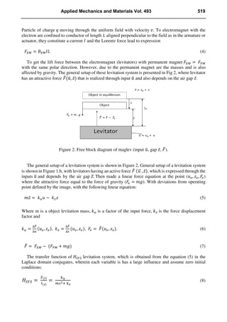
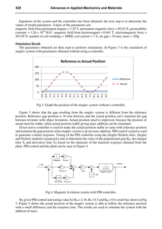
This paper proposes a magnetic levitation model using PID control. The model uses permanent magnets and electromagnets to generate magnetic levitation force and maintain a stable gap between the levitating object and the levitator. Simulation results show that while the initial model could not maintain a stable gap, adding PID control allowed the actual position to follow the reference position closely. Further simulations adding mass in stages showed that the PID controlled model could maintain the gap width, though a small 1mm difference occurred with the largest added mass of 150g. The study provides a preliminary simulation of a magnetic levitation system that could be further developed to maintain the desired gap even with added actual mass loads.
![Preliminary Study on Magnetic Levitation Modeling Using PID Control
Desmas A Patriawan 1
, Bambang Pramujati 2
and Hendro Nurhadi 3
1,2,3
Mech. Eng. Dept., Institut Teknologi Sepuluh Nopember (ITS), Surabaya 60111, Indonesia.
1
patriawan87@gmail.com , 2
pramujati@me.its.ac.id, 3
hdnurhadi@me.its.ac.id
Keywords: modeling magnetic levitation, PID control, gap, electromagnet
Abstract. This paper proposes to understand about basic magnetic levitation model. Magnetic
Levitation is repulsive or attractive force resulting gap from magnetic field. Characteristic of the
magnetic levitation model is used permanent magnet and electromagnet with PID control to maintain
wide gap between levitator and object levitation. Mass addition is used to analysis the model of the
Maglev with PID control to maintain wide gap. Calculation result show that the maglev with PID
control has sufficient levitation force in the maintain wide gap. Comparison between calculated and
measured values can be done to build a another complex model magnetic levitation.
Introduction
Development modern transport systems has been something important. Condition transportation
system that today are cause various problems, such as pollution increases, limited energy source and
expensive for daily operation. Magnetic levitation (maglev) is a one of new method that used for
modern transportation system. The system is made a vehicle lifted from the road way or guide way by
a magnetic field. The high magnetic levitation force makes possible various applications, not only
transportation system, but magnetic bearing, flywheel and motors or generators.
Superconductor YBa2Cu3O7-x (YBCO) and electromagnet can produce magnetic levitation,
which this system resulting equations for lift to weight, suspension stiffness and lateral stiffness
[1][2]. However, using the superconductor it be difficult to applied in the form real vehicle, because
the superconductor only work at temperatures -1970
C.
Source magnet field (flux) has a different character depending on the type of field. There are three
types of fields, the uniform, non uniform and variable [3]. In research to determine the costs is an
important part, especially to reduce the costs required to make magnetic levitation equipment with
low cost [4].
Research on magnetic levitation has been developed, to create a new conveyor passive systems
based on magnetic levitation bearings [5], maglev car with a miniature model of YBCO
superconductor [6], the trajectory of permanent magnet made in the form of a "V" [7] and to observe
the effects of dynamics and response learning physics with this method [8]. Setting gap of the maglev
is an important, because the gap of the maglev needs to be constant and stable. Therefore the control
of the maglev system using electromagnets can be well controlled. Arrangement with zero-power
controller to produce maglev and the proportional-integral-derivative (PID) controller is used to
adjust the electrostatic levitation [9].
Design of Experiments
This paper describe of modeling magnetic levitation system, also controller and mass additions.
Data obtained from Matlab simulation, the results can be used to make the maglev system. There
needs to some factors that must be considered. Permanent magnet is the part of a factors. There are
various types of the permanent magnets that are now used. In table 1 we can see various types of
magnets with commercial characteristics.
Applied Mechanics and Materials Vol. 493 (2014) pp 517-522
© (2014) Trans Tech Publications, Switzerland
doi:10.4028/www.scientific.net/AMM.493.517
All rights reserved. No part of contents of this paper may be reproduced or transmitted in any form or by any means without the written permission of TTP,
www.ttp.net. (ID: 140.0.156.247-02/01/14,04:47:57)](https://image.slidesharecdn.com/930a8ba1-25c4-45df-8bc5-db1c2919031f-161216013708/85/Desmas-2014-Preliminary-Study-on-Magnetic-Levitation-Modeling-Using-PID-Control-1-320.jpg)
![Preliminary Study on Magnetic Levitation Modeling Using PID Control
Desmas A Patriawan 1
, Bambang Pramujati 2
and Hendro Nurhadi 3
1,2,3
Mech. Eng. Dept., Institut Teknologi Sepuluh Nopember (ITS), Surabaya 60111, Indonesia.
1
patriawan87@gmail.com , 2
pramujati@me.its.ac.id, 3
hdnurhadi@me.its.ac.id
Keywords: modeling magnetic levitation, PID control, gap, electromagnet
Abstract. This paper proposes to understand about basic magnetic levitation model. Magnetic
Levitation is repulsive or attractive force resulting gap from magnetic field. Characteristic of the
magnetic levitation model is used permanent magnet and electromagnet with PID control to maintain
wide gap between levitator and object levitation. Mass addition is used to analysis the model of the
Maglev with PID control to maintain wide gap. Calculation result show that the maglev with PID
control has sufficient levitation force in the maintain wide gap. Comparison between calculated and
measured values can be done to build a another complex model magnetic levitation.
Introduction
Development modern transport systems has been something important. Condition transportation
system that today are cause various problems, such as pollution increases, limited energy source and
expensive for daily operation. Magnetic levitation (maglev) is a one of new method that used for
modern transportation system. The system is made a vehicle lifted from the road way or guide way by
a magnetic field. The high magnetic levitation force makes possible various applications, not only
transportation system, but magnetic bearing, flywheel and motors or generators.
Superconductor YBa2Cu3O7-x (YBCO) and electromagnet can produce magnetic levitation,
which this system resulting equations for lift to weight, suspension stiffness and lateral stiffness
[1][2]. However, using the superconductor it be difficult to applied in the form real vehicle, because
the superconductor only work at temperatures -1970
C.
Source magnet field (flux) has a different character depending on the type of field. There are three
types of fields, the uniform, non uniform and variable [3]. In research to determine the costs is an
important part, especially to reduce the costs required to make magnetic levitation equipment with
low cost [4].
Research on magnetic levitation has been developed, to create a new conveyor passive systems
based on magnetic levitation bearings [5], maglev car with a miniature model of YBCO
superconductor [6], the trajectory of permanent magnet made in the form of a "V" [7] and to observe
the effects of dynamics and response learning physics with this method [8]. Setting gap of the maglev
is an important, because the gap of the maglev needs to be constant and stable. Therefore the control
of the maglev system using electromagnets can be well controlled. Arrangement with zero-power
controller to produce maglev and the proportional-integral-derivative (PID) controller is used to
adjust the electrostatic levitation [9].
Design of Experiments
This paper describe of modeling magnetic levitation system, also controller and mass additions.
Data obtained from Matlab simulation, the results can be used to make the maglev system. There
needs to some factors that must be considered. Permanent magnet is the part of a factors. There are
various types of the permanent magnets that are now used. In table 1 we can see various types of
magnets with commercial characteristics.
Applied Mechanics and Materials Vol. 493 (2014) pp 517-522
© (2014) Trans Tech Publications, Switzerland
doi:10.4028/www.scientific.net/AMM.493.517
All rights reserved. No part of contents of this paper may be reproduced or transmitted in any form or by any means without the written permission of TTP,
www.ttp.net. (ID: 140.0.156.247-02/01/14,04:47:57)](https://image.slidesharecdn.com/930a8ba1-25c4-45df-8bc5-db1c2919031f-161216013708/75/Desmas-2014-Preliminary-Study-on-Magnetic-Levitation-Modeling-Using-PID-Control-1-2048.jpg)
![Table1. Commercial characteristics of the magnetic [3].
From Table 1 it can be seen that the Nd2Fe14B or neodymium has greater value when compared to
other types of permanent magnets, so the modeling will be using neodymium material.
Figure 1 show magnetic levitation system. Permanent magnets used have cylindrical shape where
is the inner radius and the is the outer radius of the cylinder. Pole located at the center of the
magnet is used to keep the magnet does not move left or right.
Figure 1. Magnetic levitation system.
From cylindrical shape used in maglev systems, the resulting magnetic field can be written [3]:
(1)
when is permanent flux density of the permanent magnet and is magnetic field permanent
magnet. While electromagnets used is the solenoid, the equation can be written:
(2)
is permeability current, is current through the solenoid and is the number of turns per unit
length to solenoid.
Form equation 1 and 2 found that the magnetic force. Equation of magnetic force is obtained from
the Lorentz equation, for the force generated from the permanent magnet can be written:
(3)
518 Advances in Applied Mechanics and Materials](https://image.slidesharecdn.com/930a8ba1-25c4-45df-8bc5-db1c2919031f-161216013708/85/Desmas-2014-Preliminary-Study-on-Magnetic-Levitation-Modeling-Using-PID-Control-2-320.jpg)
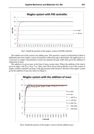
![Figure 6 it shown that the maglev system with PID control is help to maintain a wide gap.
However, still have small difference between reference position and maglev system with mass
addition. The result shown if maglev system given more mass addition the system is difficult to
control the difference gap between actual position with reference position.
Conclusion
Research results be obtained that the maglev system is being designed and tested by simulation is
not able to maintain a wide gap between the object in levitators. By the addition of the PID controller
simulation results show that the maglev system can follow from the position of the reference.
The addition of a given mass on maglev system is also not very influential, although the addition of
the masses to make the position of the levitated object moved by 1 mm from the reference position.
This study as a simulation of a maglev system to be developed, so that when there is the addition of
the actual mass of the system can maintain the expected gap.
References
[1] Y. Iwasa and H. Lee, ’Electromaglev’-magnetic levitation of a superconducting disk with a DC
field generated by electromagnet: Part 1. Theoritical and experimental result on operating modes,
lift-toweight ratio, and suspension stiffness, International Journal of Cryogenics. 37 (1997) 807-816.
[2] H. Lee., M. Tsuda and Y. Iwasa, ’Electromaglev’-magnetic levitation of a superconducting disk
with a DC field generated by electromagnet: Part 2. Theoritical and experimental result on
lift-to-weight ratio and lateral stiffness, International Journal of Cryogenics. 38 (1998) 419-427.
[3] J.M.D. Coey, Permanent Magnet Applications, International Journal of Magnetism and
Magnetic Material. 248 (2002) 441-456.
[4] K. A. Lilienkamp and Kent Lundberg, Low-cost magnetic levitation project kits for teaching
feedback system design. Submitted to American Control Conference. (2004)
[5] T. Ohji., S. Ichiyama., K. Amei., M. Sakui and S. Yamada, A new conveyor system based on
passive magnetic levitation unit having repulsive-type magnetic bearing. Journal of Magnetism and
Magnetic Materia. (2004) 272-276.
[6] R.M. Stephan, et al. A superconducting levitation vehicle prototype. Journal of Physica C (2004)
932-934.
[7] G. D’Ovidio., F. Crisi., G. Lanzara, A “V” shaped superconducting levitation modul for lift and
guidance of a magnetic transportation system. Journal of Physica C. Vol 468 (2008) 1036-1040.
[8] St. Rosenzweig, et al. A superconducting levitation transport model system for dynamical and
didactical studies. Journal Physics Prodia. Vol 36 (2012) 1037-1042.
[9] E. West., A. Yamamoto., T. Higuchi. Automatic object release in magnetic and electrostatic
levitation system. International Journal of Precision Engineering. Vol. 33 (2009) 217-228.
522 Advances in Applied Mechanics and Materials](https://image.slidesharecdn.com/930a8ba1-25c4-45df-8bc5-db1c2919031f-161216013708/85/Desmas-2014-Preliminary-Study-on-Magnetic-Levitation-Modeling-Using-PID-Control-6-320.jpg)


