Micro Focus DevOps Drive-in with Gary Gruver - Starting and Scaling DevOps in...Serena Software
In this o-demand webcast Gary presents his recommendations from his new book “Starting and Scaling DevOps in the Enterprise”. Don't miss this Q&A section with Gary where he answers questions about how to implement his pragmatic ideas and techniques in your organization's DevOps Journey.
This is the term project report for an Optical Mount project for MCHE 1940: Mechanical Engineering Design Studio
& Professional Practice, University of Georgia, Freshman Year
A Better Way to Capture and Manage Cement Lab Datapvisoftware
The design and test of cement slurries are integral parts of every cementing job. Variability between wells can make this process time-consuming and expensive. This white paper talks about how to use an integrated database management application to formulates slurries, calculates required weights for all ingredients, generates weight-up sheets, stores test results, and generates lab reports from anywhere, at any time.
During the 6-week internship on Advanced SolidWorks, I gained expertise in various topics
including Design Tables and Configurations, Assemblies Advanced Mates, Assemblies Deep-
Dive, and successfully completed a final project focused on designing a Radial Engine.
In the Design Tables and Configurations module, I learned how to create and manage design
tables, enabling efficient parametric design changes and customization options. I became
proficient in configuring parts and assemblies using different design configurations, optimizing
flexibility and adaptability in engineering designs.
The Assemblies Advanced Mates module allowed me to explore advanced mating techniques,
such as symmetric mates, path mates, and mechanical mates. I mastered the skill of creating
complex assemblies, ensuring precise and accurate component alignment and motion simulation.
In the Assemblies Deep-Dive module, I delved deeper into assembly techniques, learning about
sub-assemblies, exploded views, and the use of mate references. I acquired a comprehensive
understanding of organizing complex assemblies and effectively communicating design intent
through exploded views.
For my final project, I undertook the challenging task of designing a Radial Engine. This
involved creating the individual engine components, designing mating features, applying
advanced mates, and ensuring proper functionality and realistic motion. Through this project, I
applied my knowledge and skills acquired throughout the internship to create a functional and
visually appealing radial engine model.
Overall, this internship provided me with a comprehensive understanding of Advanced
SolidWorks techniques, enabling me to efficiently design, configure, and assemble complex
engineering models. I am confident that the skills and knowledge gained during this internship
will greatly contribute to my future endeavors in the field of mechanical engineering and product
design.
Modeling and Analysis of Support Pin for Brake Spider Fixture by Fem Using An...IOSR Journals
Abstract: A fixture is designed and built to hold, support and locate every component to ensure that each is
drilled or machined with accuracy and manufactured individually. A fixture can be designed for a particular
job. A brake spider includes a spider body with a central opening and a slot for receiving a camshaft and
bracket assembly. The brake spider is attached to axle housing via the central opening. The form to be used
depends on the shape and requirement of the work piece to be machined. In the existing fixture, used for
modeling brake spider component, only five components were machined per hour. In the present work, detailed
study of brake spider component is carried out and design is modified to increase the productivity. The new
fixture design is carried out by using CATIA V5 modeling software and it is critically evaluated for the failure of
support pin component, by finite element method (FEM) using ANSYS software. This modified design is adapted
in the fabrication of fixture and is tested for its productivity. It is found that there is a considerable enhancement
in the productivity to seven components per hour with required accuracy.
Key Words: Fixture; support pin; ansys; brake spider; CATIA V5; FEM
DESIGN AND ANALYSIS OF HEAVY VEHICLE CHASSIS USING HONEY COMB STRUCTUREIjripublishers Ijri
Automotive chassis is a skeletal frame on which various mechanical parts like engine, tires, axle assemblies, brakes,
steering etc. are bolted. The chassis is considered to be the most significant component of an automobile. It is the most
crucial element that gives strength and stability to the vehicle under different conditions.
This thesis deals with the design optimization and material suggestion for heavy vehicle chassis (container vehicle).
In the first step literature survey will be conducted for further processes (for the selection of material and geometric
selection).
In the next step modeling will be done to carry out the analysis. Structural Analysis will be conducted using traditional
material M.S; Composite materials FRP (E-glass)& Carbon epoxy (S-2 glass), also analysis will be conducted on present
and updated models.
In the next step impact test and fatigue analysis will be conducted on same to find impact and fatigue characteristics.
Objective: By doing this project chassis manufacturing company can save time & efforts because of easy manufacturing
method. End user can save money on chassis purchase and savings on reduced fuel consumption due to low weight of
chassis with composites
DESIGN AND ANALYSIS OF HEAVY VEHICLE CHASSIS USING HONEY COMB STRUCTURE
Design Portfolio Rev A 2017
1. Design Portfolio Jason Constant 1-28-17
E: Jac3004@rit.edu
M: 908-425-7616
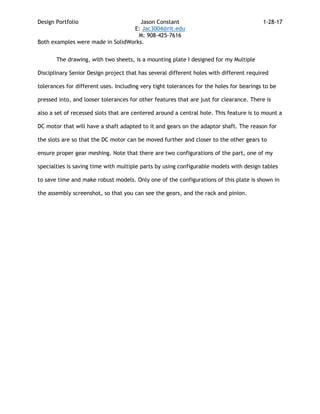
Both examples were made in SolidWorks.
The drawing, with two sheets, is a mounting plate I designed for my Multiple
Disciplinary Senior Design project that has several different holes with different required
tolerances for different uses. Including very tight tolerances for the holes for bearings to be
pressed into, and looser tolerances for other features that are just for clearance. There is
also a set of recessed slots that are centered around a central hole. This feature is to mount a
DC motor that will have a shaft adapted to it and gears on the adaptor shaft. The reason for
the slots are so that the DC motor can be moved further and closer to the other gears to
ensure proper gear meshing. Note that there are two configurations of the part, one of my
specialties is saving time with multiple parts by using configurable models with design tables
to save time and make robust models. Only one of the configurations of this plate is shown in
the assembly screenshot, so that you can see the gears, and the rack and pinion.
2.
3.
4. In these screenshots of a large assembly for my senior design project, both
configurations of the mounting plate are used. In the first image, the top plate is shown as
transparent, in the top view in the second image, it is hidden. I designed the concept of this
assembly with teammates, but I was solely responsible for modeling each part in this
assembly. Making assemblies clean and simple is a huge priority in my designs. I always make
sure that you can actually put my assemblies together easily in the real world.
This model includes 139 components, including lots of hardware. One of the other
challenges that I overcame in this particular assembly was to use uniform hardware wherever
possible to reduce the number of tools required to assembly the prototype. Finally, I paid
close attention to the fine points of this design, such as making the system have integrated
adjustment capabilities, which can allow our team to use different springs, finely tune the
rack’s travel distance, and to use as many off-the-shelf parts as possible.
I used a variety of mates in assembly, including rack and pinion mates, gear mates,
mirrors, and patterns. There is also a hierarchy in this model, because there were too many
components to fit into this one assembly cleanly, so there are at least three sub-assemblies
under this assembly to make it load faster and to be allow this to be assembled in a more
streamlined process.