Download to read offline
![Akshay Vaishnav1
.et. al. Int. Journal of Engineering Research and Applications www.ijera.com
ISSN: 2248-9622, Vol. 6, Issue 5, (Part - 4) May 2016, pp.58-66
www.ijera.com 59 | P a g e
the press design based on Computer Aided Design.
They presented work of C-type hydraulic press,
which is divided into two hypothetical parts to
decrease the computational time approximately 70%.
The press is applied 981 kN of load. Shell elements
of 6 DOF were used for modelling for the in-plate
membrane behavior and out-of-plane bending.
Effects of fillet, edge cutting, opening and eccentric
loading were studied on the deformation of the
frame of the machine. The permissible deformation
for this work was taken 0.5 mm/m [1].
Mohamad M. Saleh (1992) describes the
systematic procedure for investing the performance
and the design analysis of the welded structure of a
150-ton hydraulic press. The investigation discusses
the theoretical and experimental model of the
machine to establish the accurately optimal design
analysis and further development of the present
machine at minimum time and lower cost. The
theoretical model takes into account both
conventional analytical formula and numerical
technique, using Finite Element Analysis. Here, the
objective of modelling the structure of this press is
to establish an empirical method of calculation in
which the stiffness and the strength of the press
structure can be obtained. The data acquisition
system in the current work has been designed to
establish a versatile measurement system so that
processing of the experimental variables of interest
can be measured by the computer. It was concluded
that the press structure was more flexible in the
plane stress FEA model than 3D thin shell FEA
model by about 2%. This suggested that a new
design of press structure which converged to within
4% lower than that indicated by the design goal of
the press structure [2].
Malachy Sumaila et al. (2011) gave the
procedure for designing and manufacturing of a 30-
ton Hydraulic press. The initial dimension for
cylinder and the load were assumed to be 150 mm
and 300 kN load respectively. Cylinder End-Cover
Plate, Bolt, Cylinder Flange, Piston, Seals were
designed using standard design procedure. The
machine was then subjected to a load of 10 kN
provided by two compression springs of constant 9
N/mm each arranged in parallel between the plates.
The springs were then compressed axially to a length
of 100 mm. This arrangement was left to stand for
two hours and was observed for leakages. Leakage
in the system was not indicated as the lower plate
did not fall from its initial position [3].
Optimization in every design is necessary.
It reduces many factors in terms of costs,
manufacturing, material etc. Muni Prabaharan et al.
(2011) presented the work of optimization of 5 Ton
Hydraulic Press and Scrap Baling press for cost
reduction by Topology. The cost is reduced by
reduction of material; therefore, the thickness of the
press frame is reduced further from 10 mm. From
the results, it is concluded that 26.36% volume
reduction for scrap baling press and 24.54% for
hydraulic press [4].
In designing of hydraulic press, both
analytical and FEA methods are used in general
case. Cătălin Iancu (2013) compared the analytical
and FEA methods for designing of Mechanical press
bed. Open section frames with closed contour
section were used. It was found that closed frames
are approximately 15% more rigid than open
frameworks, the decisive factor in choosing the
technology and construction of the frame being
technical-economic considerations. The 3D model
was generated using CAD tools, which is simulated
by FEA tool. Based on FEA application the results
show a continuous distribution of displacements and
stresses that validate the model, proving it correct. It
can be noticed that stress values are generally low
compared with traction-compression strength of bed
material, higher values being recorded only locally.
The results of both methods show that, the stress
values obtained by classical calculus are higher than
obtained by FEA, conforming the assumption that
using only a calculation based on the simplified
structure, leads to an oversized structure, the
calculation method being usually used for
verification [5].
Ankit Parmar et al. (2014) demonstrated the
FEA based design and optimization of foremost
element of hydraulic press machine. The main
components focused are top plate, movable plate and
column design. The load was assumed to be 300-
tons. Several design iterations were performed for
designing the plates followed by some simulations.
After every simulation, the design is modified each
time. The sizing optimization approach was used for
this work. In this work, various size parameters like
plate thickness, bar cross sectional areas are
modified to design the structure under safe
conditions. For final design, the weight of bottom
plate was reduced from 2263 kg to 1303 kg.
Deformation is increased from 0.055 mm to 0.22
mm, which is still in permissible limit. Von-misses
stress is increased from 104 MPa to 141 MPa, which
is also in permissible limit and under safe working
condition [7].
Sizing optimization is a very useful method
in designing of press machines. Pritesh Prajapati et
al. (2014) presented work on design and
modification of hydraulic press based on that
method. Different thirty iterations were performed
proposing different deigns. The material used for
plate and structure is Stainless Steel with minimum
allowable deformation under 5 mm/m. The weight of
plate is reduced quite significantly due to the
optimization process, but the values of deformation](https://image.slidesharecdn.com/i0605045866-160811040821/75/Design-Optimization-of-Hydraulic-Press-Plate-using-Finite-Element-Analysis-2-2048.jpg)
![Akshay Vaishnav1
.et. al. Int. Journal of Engineering Research and Applications www.ijera.com
ISSN: 2248-9622, Vol. 6, Issue 5, (Part - 4) May 2016, pp.58-66
www.ijera.com 60 | P a g e
and stress increase, which is still under permissible
values for safe design [8].
The study on C-type power press was done
by D. Ravi (2014) under static conditions. The
capacity of press is 10 tons. The 3D model of the
power press was analyzed in static condition to find
the stresses and deflections in the structure. The
second stage of work includes the reduction in
weight of the power press by varying the thickness
of bed and frame. A CAD assembly was generated
using CAD tools and assembly features. This
assembly was subjected to FEA analysis. In the
existing design the structure, 56.68 N/mm2
stress
was acting with 1.533 mm of maximum
deformation. After being modified and redesigned,
the value of stress becomes 56.42 N/mm2
with the
maximum deformation of 1.647 mm. Due to
decrement of bed and frame thickness, the weight
machine was reduced from 1920 kg to 1660 kg [9].
The design optimization and analysis of
structure of a heavy duty forming hydraulic press
were carried out by Abhijeet S Khandekar (2015).
The work was proposed for 300-ton capacity of
machine. Conventional design calculations were
made assuming the plate structure as a simple beam.
The load is applied at the center of the beam. Stress
generated from the conventional design calculations
is 150 Kg/cm2
[11]. A review paper was presented
by Asim M. Kamte et al. (2015) on design analysis
of a 20-ton hydraulic press. The optimization of all
parts is done by FEA method, which will help to
reduce the unwanted stress [12].
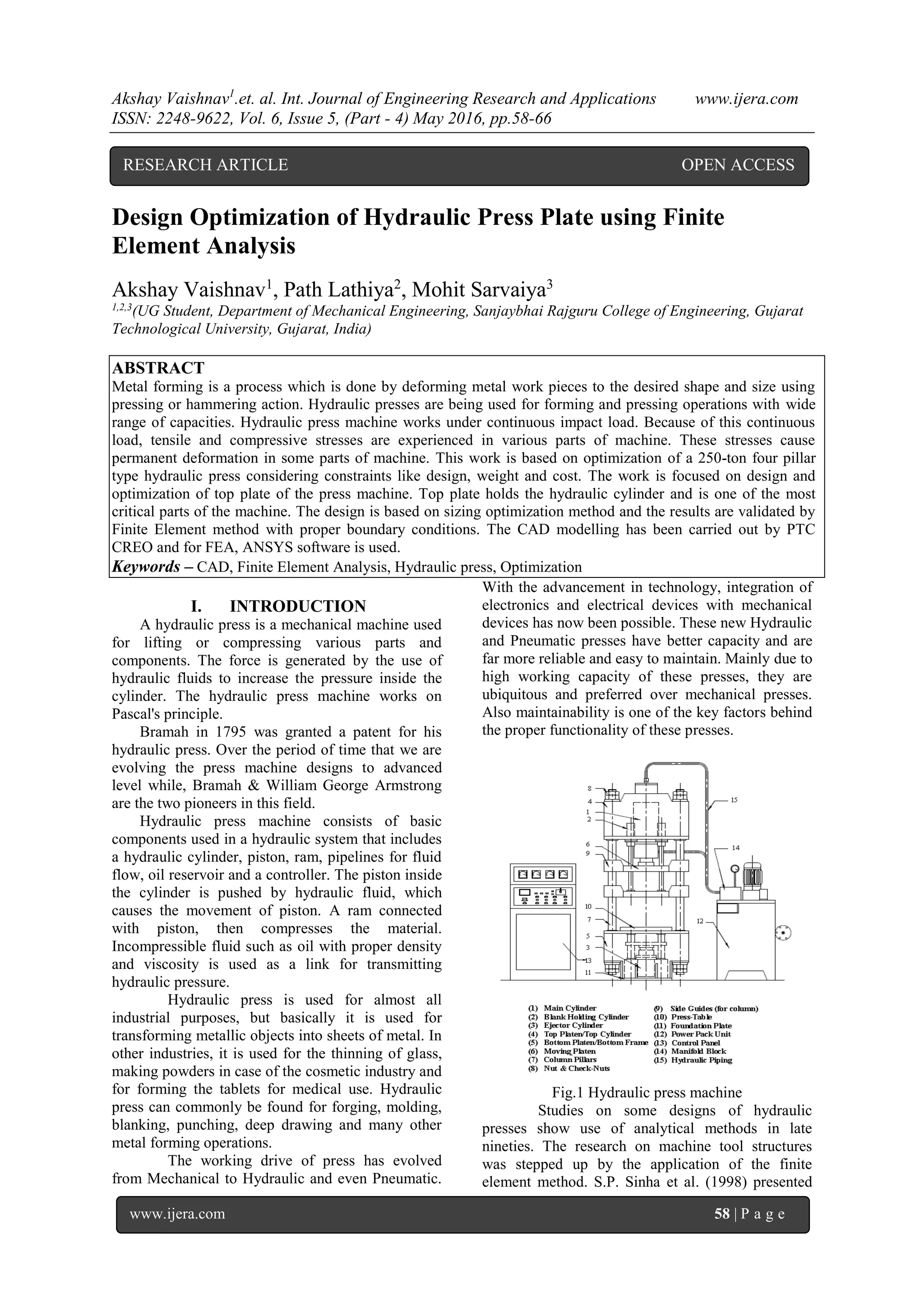
II. PROBLEM STATEMENT
Every design starts with the conventional
calculations by applying various fundamentals of
design. The top plate is subjected to pure bending
stress during the operation. Therefore, design
considerations are essential for plates subjected to
bending stress. The dimensions of base plate, used
for top plate,
Table 1: Geometrical dimensions
Constraint Value
Breath (b) 860 mm
Height (h) 558.6 mm
Depth (d) 60 mm
Maximum applied load 250 tons
Based on the theoretical calculations and
design, we can model and simulate the system into
various software packages for validation. The
theoretical calculations are based on conventional
machine design using a set of equations. This gives
the basic idea of the design of the product.
Fig. 2 Load case
When a static or dynamic load acts on any
part of hydraulic press, then along with simple,
tensile, compressive, shear stress, it also develops
bending stress.
Consider a beam subjected to a bending moment M,
The bending equation is given by,
(1)
Where,
M = Bending moment at the given section
= Bending stress
I = Moment of inertia of the cross-section about the
neutral axis.
y = Distance from the neutral surface to the extreme
fiber
Bending moment is given by,
(2)
= 5.375e8 N-mm
Moment of inertia of the cross-section about the
neutral axis,
= = 8.71e8 mm4
= = 279.3 mm
Putting these values in Eq. (1)
=
172.09 N/mm2
= 172.09 MPa
The ultimate tensile strength of mild steel is,
460 MPa, Considering Factor of Safety = 2.5
for the given structure.
According to Maximum Principal stress theory,
184 MPa
So, <](https://image.slidesharecdn.com/i0605045866-160811040821/75/Design-Optimization-of-Hydraulic-Press-Plate-using-Finite-Element-Analysis-3-2048.jpg)


![Akshay Vaishnav1
.et. al. Int. Journal of Engineering Research and Applications www.ijera.com
ISSN: 2248-9622, Vol. 6, Issue 5, (Part - 4) May 2016, pp.58-66
www.ijera.com 65 | P a g e
253.24
302.22
350.89
400.11
447.45
0
50
100
150
200
250
300
350
400
450
500
100 150 200 250 300
Weight(Kg)
Rib Height (mm)
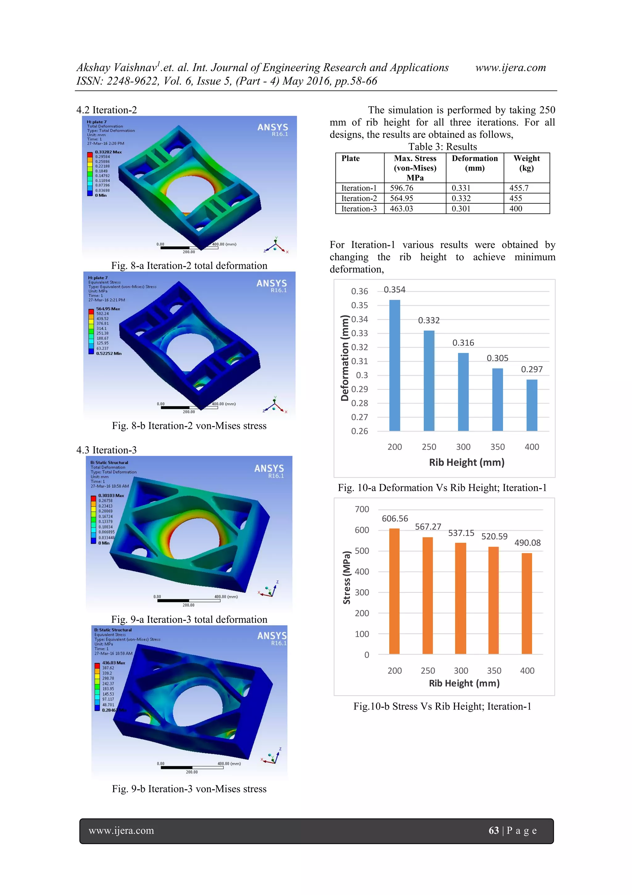
Fig. 12-c Weight Vs Rib Height; Iteration-3
V. CONCLUSION
From sizing optimization method, the
design is modified by incremental iteration
approach. For 250 mm of rib height, the FEA results
were obtained. It is found that Iteration-3 is optimum
design and has deformation under desired values.
Also the maximum von-Mises stress for that design
is less than the ultimate tensile stress of the material,
so this design is safe.
For other designs, the attempt was made to
restrict the overall deformation under 0.3mm/m.
This is done by changing the rib height of the plate.
Comparison of these results is shown in graphs.
From these results it is found that for Iteration-1, the
desirable deformation can be achieved by putting the
rib height of 350 mm. For this height the value of
maximum von-Mises stress is 520.29 MPa and the
weight is 571.87 kg. For Iteration-2, the desirable
deformation can be achieved by taking 450 mm of
rib height with the value of maximum von-Mises
stress is 484.43 MPa and the weight of 678.31 kg.
For Iteration-3, the desirable deformation can be
achieved by putting 250 mm of rib height with the
maximum value of von-Mises stress of 393.57 MPa
and the weight of 400 kg.
So, from the above results, it is concluded
that design-3 can be proposed for manufacturing. It
has much lower weight compared to other designs,
so material cost can be saved. Also it fulfills all the
design constraints. It can be manufactured by casting
method.
REFERENCES
[1] S. P. Sinha, P.D. Murarka, Computer-Aided
design of Hydraulic Structures, Math1
Computer Modelling, Vol. 10, No. 9, pp.
637-645, 1988
[2] Mohamad M. Saleh, Design Study of a
Heavy Duty Hydraulic Machine using
Finite Element Techniques, Ph. D Thesis,
Dublin City University, August, 1992
[3] Malachy Sumaila, Akii Okonigbon
Akaehomen Ibhadode, Design and
Manufacture of a 30-ton Hydraulic Press,
AU J.T. 14(3): 196-200 Jan. 2011
[4] Muni Prabaharan and V.Amarnath,
Structural Optimization of 5-Ton Hydraulic
Press and Scrap Baling Press for Cost
Reduction by Topology, International
Journal of Modeling and Optimization, Vol.
1, No. 3, August 2011
[5] Cătălin Iancu, Comparison between
Analytical Calculus and FEM for a
Mechanical Press Bed, American Journal of
Mechanical Engineering, Vol. 1, No. 1, 6-
13, 2013
[6] Jiafeng Yao, Baochun Lu, Chris Zhang and
Michio Sadatomi, Optimal Design of
Hydraulic System for an Industrial Press
Machine for Performance Improvement and
Noise Reduction, Open Journal of
Mechanical Engineering, Vol.1 No.3, pp 1-
16, 2013
[7] Ankit H Parmar, Kinnarraj P Zala and
Ankit R Patel, Design and Modification of
Foremost Element of Hydraulic Press
Machine, International Journal of
Advanced Scientific and Technical
Research Issue 4 volume 3, May-June 2014
[8] Pritesh Prajapati and Ankit Parmar, Design
and Modification of Hydraulic Press,
International Journal of Engineering
Development and Research, Volume 2,
Issue 2, 2014
[9] D. Ravi, Computer Aided Design and
Analysis of Power Press, Middle-East
Journal of Scientific Research 20 (10):
1239-1246, 2014
[10] Amith Kalekar and S. B. Tuljapure, Stress
Analysis of a Frame of a Bush Pressing
Machine for Pumps, International Journal
of Innovative Research in Science,
Engineering and Technology, Vol. 4, Issue
2, February 2015
[11] Abhijeet S Khandekar, Conventional
Design Calculation &3D Modeling of
Metal Forming Heavy duty Hydraulic
Press, International Journal of Engineering
Research and Applications, Vol. 5, Issue 6,
Part – 5, pp.100-103, June 2015
[12] Asim M.Kamate and Prof. Dr. J.S. Bagi, A
Review on Design Analysis and
Optimization of a 20 Ton Hydraulic Press,
International Journal of Engineering
Technology, Management and Applied
Sciences, Volume 3, Special Issue, ISSN
2349-4476, September, 2015](https://image.slidesharecdn.com/i0605045866-160811040821/75/Design-Optimization-of-Hydraulic-Press-Plate-using-Finite-Element-Analysis-8-2048.jpg)
![Akshay Vaishnav1
.et. al. Int. Journal of Engineering Research and Applications www.ijera.com
ISSN: 2248-9622, Vol. 6, Issue 5, (Part - 4) May 2016, pp.58-66
www.ijera.com 66 | P a g e
[13] Mr. Umesh C. Rajmane, Mr. Sourabh S.
Kulkarni and Prof. Dr. A.M.Nagaraj,
Design, Development and Stress Analysis
for Twin Punching 100 ton Forging press,
International Journal of Advanced Research
in Science, Engineering and Technology,
Vol. 3, Issue 1 , January 2016.
[14] ANSYS user guide
[15] RK Jain, 2014, Production Technology
Khanna Publications, Delhi
[16] Robert D. Cook, 2001, Concepts and
Applications of Finite Element Analysis
Wiley Publication, NY
[17] Khurmi and Gupta, 2011, A Textbook of
Machine Design S Chand Publication,
Delhi](https://image.slidesharecdn.com/i0605045866-160811040821/75/Design-Optimization-of-Hydraulic-Press-Plate-using-Finite-Element-Analysis-9-2048.jpg)

The document discusses the design optimization of a 250-ton four-pillar hydraulic press using finite element analysis (FEA). It focuses on the critical top plate design, which is essential for the machine's operation, and presents various design iterations using CAD modeling and FEA simulation to ensure safe and efficient performance. The study concludes with results indicating stresses and deformations within permissible limits after applying different design modifications.