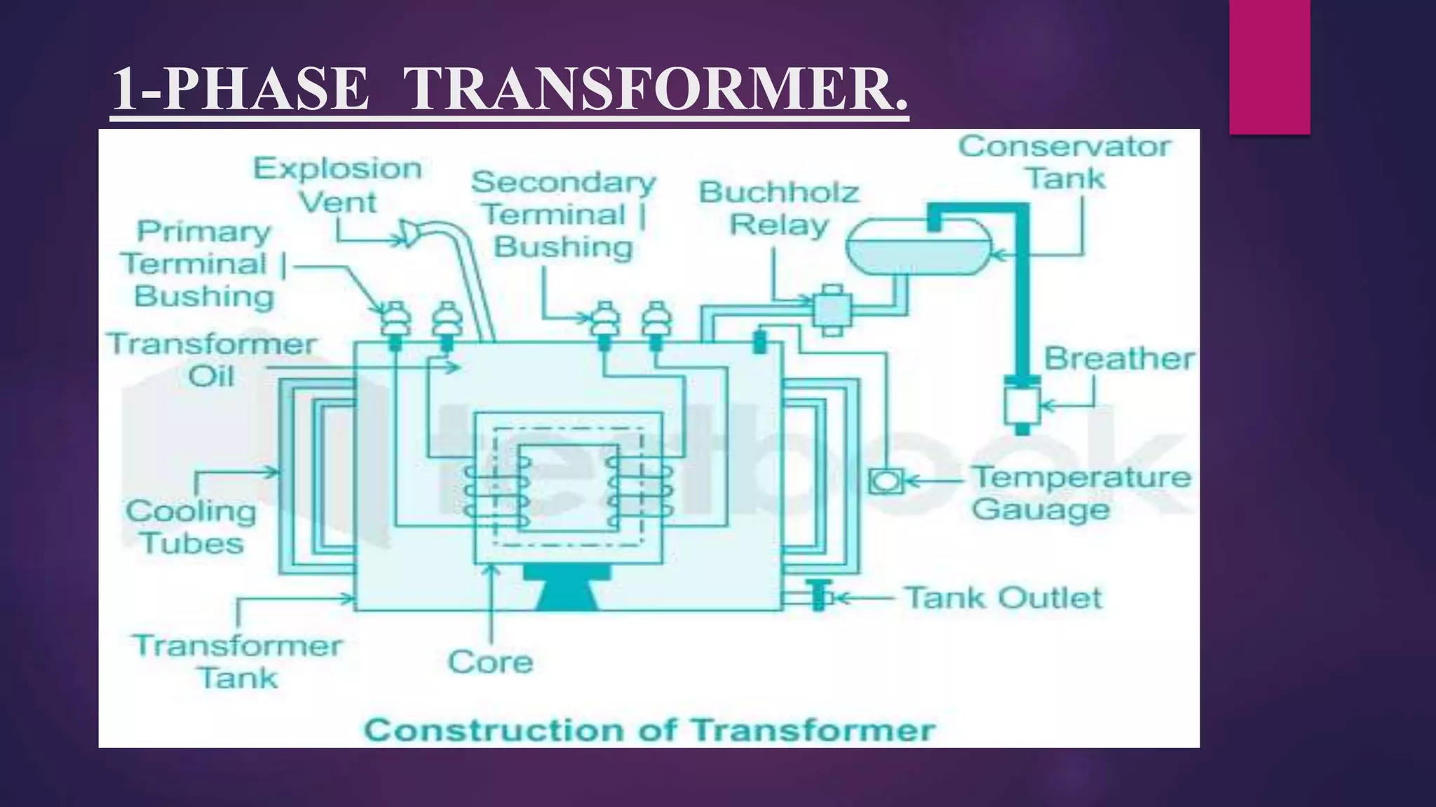
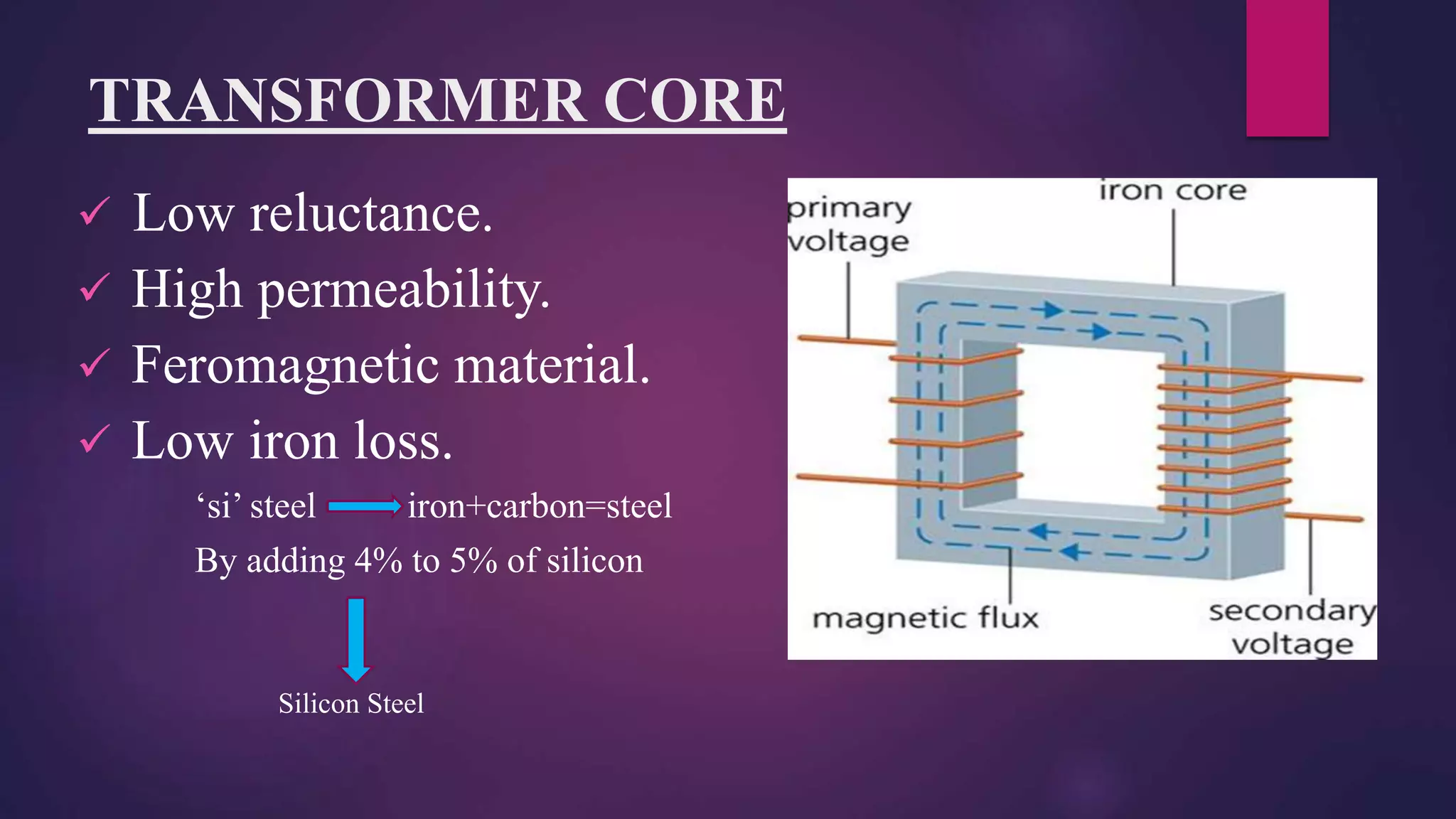
DEPARTMENT OF ELECTRICALAND ELECTRONICS ENGINEERING
TECHNICAL SEMINAR
DESIGN OF SINGLE PHASE TRANSFORMER
PRESENTED BY
V.RAHUL
2065FA0206
DEFINITION AND FEATURES OF TRANSFORMER
 Definition:-
 It is a static device transfer power from one circuit to another
circuit .
 Features:-
 It is a constant frequency device.
 Constant power device .
 It is a constant flux device .
 It is a 180 degree phase shift
 It is an electromagnetic energy conversion device(internal energy
conversion).
CONSTRUCTION OF TRANSFORMER
We have mainly two parts.
1. Transformer core.
2. Transformer winding.
1-PHASE TRANSFORMER.
TRANSFORMER CORE
 Low reluctance.
 High permeability.
 Feromagnetic material.
 Low iron loss.
‘si’ steel iron+carbon=steel
By adding 4% to 5% of silicon
Silicon Steel
HOW SHOULD BE THE CORE
 Consider a solid core.
 The current carrying capacity is
depend the cross sectional are of
conductor.
 Eddy current losses takes place in
the form of heat.
 Due to induced emf in the core eddy current flows(Ie)
 Each and every material offers some amount resistance.
 So, finally due to this Ie^2Rc losses produces. (Rc= Core resistance)
CONSIDER A LAMINATED CORE.
 In order to over come the drawbacks of solid core we need to
make the laminations.
 Cros sectional area of the core is reduced.
 Insulating medium is oxide paint, chaina clay, Japan varnish.
SHAPE OF SILICON STEEL
 Crystal structure called BCC –(BODY CENTRE CUBIC
STRUCTRE)
 In silicon steel we have lakhs of cubes/grains.
 This are all microscopic pictures.
EDGES AND DIAGONELS
In this cubic structure we have edges and
diagonals.
12-Edges.
04-Diagonals.
CONSIDER DIAGONAL PATH
Diagonal is the shortest path .
But to air gap it offers high reluctance path.
CONSIDER A SMALL PIECE OF SILICON STEEL
Normal silicon steel:
 There is non-orientation of cubes/grains.
 As compare to the length of the silicon material, the flux
is taking more length of the path.
DRAWBACKS OF SILICON
 Due to increase in length of the flow of flux.
 Reluctance of the steel little increases.
 But compare with any other material silicon is
best(offers low reluctance path to magnetic
flux).
 We can reduce the reluctance further .
 By converting non-oriented grains into oriented
grains.
PROCESS TO COVERT NON- ORIENTED GRAINS
INTO ORIENTED GRAINS
 In Mechanical Engineering we have two
process.
1.Hard Rolling Process.
2.Cold Rolling Process.
 In order to achieve orientation of
cubes/grains we need to go for cold rolling.
Cold Rolling Process
 The cold rolling process is performed under some
temperature and pressure.
 As compare to hard rolling process it is very low
(60degrees to 100degree Celsius).
Conclusion
 By the cold rolling process the silicon steel is
converted into cold rolled grain oriented steel
(CRGO STEEL).
 As path of flux is reduces .
 Reluctance is reduced.
 Reduced losses.
 Higher efficiency.
Thank You

Design of single phase transformer.pptx

  • 1.
    DEPARTMENT OF ELECTRICALANDELECTRONICS ENGINEERING TECHNICAL SEMINAR DESIGN OF SINGLE PHASE TRANSFORMER PRESENTED BY V.RAHUL 2065FA0206
  • 2.
    DEFINITION AND FEATURESOF TRANSFORMER  Definition:-  It is a static device transfer power from one circuit to another circuit .  Features:-  It is a constant frequency device.  Constant power device .  It is a constant flux device .  It is a 180 degree phase shift  It is an electromagnetic energy conversion device(internal energy conversion).
  • 3.
    CONSTRUCTION OF TRANSFORMER Wehave mainly two parts. 1. Transformer core. 2. Transformer winding.
  • 4.
  • 5.
    TRANSFORMER CORE  Lowreluctance.  High permeability.  Feromagnetic material.  Low iron loss. ‘si’ steel iron+carbon=steel By adding 4% to 5% of silicon Silicon Steel
  • 6.
    HOW SHOULD BETHE CORE  Consider a solid core.  The current carrying capacity is depend the cross sectional are of conductor.  Eddy current losses takes place in the form of heat.  Due to induced emf in the core eddy current flows(Ie)  Each and every material offers some amount resistance.  So, finally due to this Ie^2Rc losses produces. (Rc= Core resistance)
  • 7.
    CONSIDER A LAMINATEDCORE.  In order to over come the drawbacks of solid core we need to make the laminations.  Cros sectional area of the core is reduced.  Insulating medium is oxide paint, chaina clay, Japan varnish.
  • 8.
    SHAPE OF SILICONSTEEL  Crystal structure called BCC –(BODY CENTRE CUBIC STRUCTRE)  In silicon steel we have lakhs of cubes/grains.  This are all microscopic pictures.
  • 9.
    EDGES AND DIAGONELS Inthis cubic structure we have edges and diagonals. 12-Edges. 04-Diagonals.
  • 10.
    CONSIDER DIAGONAL PATH Diagonalis the shortest path . But to air gap it offers high reluctance path.
  • 11.
    CONSIDER A SMALLPIECE OF SILICON STEEL Normal silicon steel:  There is non-orientation of cubes/grains.  As compare to the length of the silicon material, the flux is taking more length of the path.
  • 12.
    DRAWBACKS OF SILICON Due to increase in length of the flow of flux.  Reluctance of the steel little increases.  But compare with any other material silicon is best(offers low reluctance path to magnetic flux).  We can reduce the reluctance further .  By converting non-oriented grains into oriented grains.
  • 13.
    PROCESS TO COVERTNON- ORIENTED GRAINS INTO ORIENTED GRAINS  In Mechanical Engineering we have two process. 1.Hard Rolling Process. 2.Cold Rolling Process.  In order to achieve orientation of cubes/grains we need to go for cold rolling.
  • 14.
    Cold Rolling Process The cold rolling process is performed under some temperature and pressure.  As compare to hard rolling process it is very low (60degrees to 100degree Celsius).
  • 15.
    Conclusion  By thecold rolling process the silicon steel is converted into cold rolled grain oriented steel (CRGO STEEL).  As path of flux is reduces .  Reluctance is reduced.  Reduced losses.  Higher efficiency.
  • 16.