Download to read offline

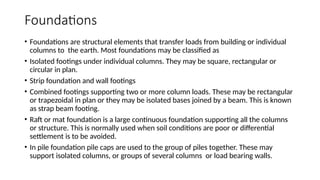
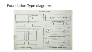
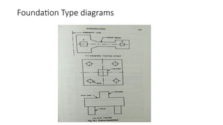
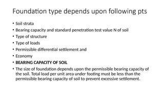
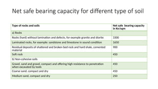
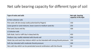
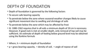

The document provides an overview of various types of foundation designs such as isolated footings, strip foundations, combined footings, and raft foundations, discussing factors influencing their selection including soil characteristics, bearing capacity, and load types. It outlines the calculation of footing dimensions based on load requirements and bearing capacity of different soil types, stressing the importance of adhering to minimum depth regulations to avoid settlement issues. Additionally, the document covers critical sections for analyzing footings under different loading conditions and shear strength considerations for design compliance.


