SlideShare a Scribd company logo
International Journal of Research and Scientific Innovation (IJRSI) | Volume IV, Issue VIS, June 2017 | ISSN 2321–2705
www.rsisinternational.org Page 49
Design and Fabrication of Manually Operated Wood
Sawing Machine: Save Electric Power
Rahul C Meshram#
#Mechanical Engineering Department, G H Raisoni College of Engineering and Management, Amravati, India
Abstract - In India power cut is big problem also having many
remote places where electricity not reached and that will affect
many small scale business and ongoing work, like Carpentry,
ongoing work got stop because of power cut. To overcome this
problem manually operated economical; conceptual model of a
machine which would be capable of performing different
operation like sawing/cutting and grinding without use of power
i.e. wood working machine is introduced.
In this paper, design concept and fabrication of manually
operated wood sawing/cutting machine is explained. It is
designed and fabricated so portable that it can be move and used
at various places. It is used for sawing/cutting of wood, plywood,
thin metals (<=2mm), and pvc pipes. The material can be cut
without any external energy like fuel or current. As machine uses
no electric power and fuel, this will help to maintain green
environment. The observations show that power required for
pedaling is well below the capacity of an average healthy human
being.
Keywords – Human Powered, sawing, wood
I. INTRODUCTION
n the today’s world, wood working operations is done in
large extent like Cutting, Drilling, and Grinding etc. For
performing these operations, we have use different type of
machines at different places, which consume lot of time and
electricity. In the rural area, electricity cut-off is a major
problem which causes discontinuity of work progress. For
avoiding this problem, we have to go for an alternative
machine called as manually operated wood working machine.
Before three to four decades, when there is unavailability of
electricity for working of different machines viz. cutting,
grinding, drilling etc. they used a manual hack saw for cutting
a wood or they used an axe to cut a wood which was a very
laborious task for humans and consumes a very much power.
But in last decades the use of an electric equipment has
increased for such an operations which is also not affordable
for a small industries or a domestic wood cutting purpose. The
used of an electrically power wood cutting and grinding
machine consumes electric power as well as cost of operation
of machines much more.
In this machine, the maximum attention is towards the saving
of electrical power, for saving this, the substitute way is a
utilization of Human power. The machine is made such that it
would be applicable to the normal field work where there is a
source of electricity. In this machine, the objective is to get
maximum machining operations. The whole machine is
running on the pedal power which produces 500W. This paper
helps to cutting and grinding operation, without any need of a
power source. It is economically efficient machine and it helps
to use for different operation without any of electricity source.
Fig 1 Schematic diagram of manually operated wood working machine.
II. LITERATURE REVIEW
1. Dharwa Chaithanya Kirthikumar, “A Research on Multi-
Purpose Machine”, International Journal for Technological
Research in Engineering (Vol.1, Issue.1, ISSN: 2347-4718)
(2013), In this paper, a human powered machine runs on chain
drives mainly with human efforts. But if you wanted to
operate this machine by electric power this machine can also
does that. It has some special attachment so use both human
power as well as electric power.
2.Dhanasegaran A, Dhilip Kumar H, Dinesh Kumar V T, Gopi
Kumar K. and S.Gokul, “Design and Fabrication of Pedal
Powered Circular Saw for Wood Working Applications”.
The objective of this paper is using the conventional
mechanical process which plays a vital role. This project
consists of a larger sprocket which rotates with a help of
human powered pedal. When the pedal is operated, circular
saw rotated which in turn cuts the wooden block material. The
main aim is to reduce the human effort for machining various
materials such as wooden blocks etc.
3.Prof. Zoeb khan, Mr.Sushil Dopekar “Design and
Fabrication of Human Powered Wood Cutting machine”
International Journal on Recent and Innovation Trends in
Computing and Communication. (ISSN: 2321-8169)
In this paper, improved design of the human powered wood
cutting machine which gives the less efforts of man and
commonly used in rural areas where there is no power supply.
I
International Journal of Research and Scientific Innovation (IJRSI) | Volume IV, Issue VIS, June 2017 | ISSN 2321–2705
www.rsisinternational.org Page 50
The design ensures a smooth operation during the cutting
process. It is light in weight and portable machine.
III. DESIGN PROCEDURE
A. Material selection
The proper selection of material for the different part of
machine is the main objective in the fabrication of machine.
For a mechanical engineer it is must that he is familiar with
the effect, which the manufacturing process and heat
treatment have on properties of material.
The choice of material for engineering purpose depends upon
the following factors:
1. Availability of material.
2. Suitability of material for the working condition in
service.
3. The cost of materials.
4. Physical and chemical properties of material.
5. Mechanical property of material.
Table 4.1 Raw Material and Standard Material Used
B. Design and modeling
Specification of Manually Operated Wood Working Machine
1. Frame width = 67 cm
2. Frame length = 152 cm
3. Frame height = 128 cm
4. Area of frame = 10184 cm2
Specification of Transmission System
1. Driving sprocket = 60 teeth
2. Driven freewheel = 18 teeth
3. Driving freewheel = 14 teeth
4. Shaft length = 45 cm
5. Bearing diameter = 2.5 cm
6. Chain length = 58 cm
7. Seat height = 75 cm
8. Handle height = 81 cm
1. Design of Flywheel
a) Calculation for Chain Drive:
Sprocket Dia. = 24 cm = 240 mm
D = dia. of pitch circle
T = number of teeth on sprocket
Find the pitch of chain
Ө = = = 60
P = 2 X X
P = 9.42 mm
Velocity ratio of chain drive
V.R. =
=
N1 = speed of rotation of freewheel in R.P.M.
N2 = speed of rotation of sprocket in R.P.M.
T1 = number of teeth on freewheel
T2 = number of teeth sprocket
V. R. =
=
= 3.33
The average velocity of chain is given by
V=
=
V = 150.8 m/s
b) Mass and Cross Section of Rim:
Outer dia. of rim=500mm
E=m*k2
*wn
2
*ks----------------------1
Where,
K =radius of gyration=Dm/2 (Dm = Mean Diameter of
Flywheel)
Dm=0.9*Do
Dm= 0.9*0.5=0.45m
K=0.45/2=0.225m
Wn = mean angular speed in rad/sec =2* *N/60
N=(750+650)/2=700rpm
Wn = (2*3.14*700)60=73.30rad/sec
From equation 1,
27=m*0.2252
*73.32
*0.02
M= 4.96Kg = 5Kg
Assuming rim provides 95% of required moment of inertia
E=0.95*I*Wn
2*
ks
I=0.2644Kg-m2
M=5.22Kg
c) Rim Cross Section:
Mass of rim=A*length*p
M=A*3.14*Dm*Density
Sr. No. Part Name Material Qty.
1 Square Pipe And Square Angle Iron 45ft
2 Pedestal Bearing C. I. and steel alloy 4
3 Sprocket Stainless Steel 1
4 Chain Alloy Steel 1
5 Pedal Cast iron 1
6 Freewheel Steel alloy 1
7 Grinding wheel Abrasive material 1
8 Cutting wheel Steel alloy 1
9 Bicycle frame Chromoly 1
10 Seat Rubber 1
11 Fastening ( Nut, Bolt, Washer ) Stainless Steel -
International Journal of Research and Scientific Innovation (IJRSI) | Volume IV, Issue VIS, June 2017 | ISSN 2321–2705
www.rsisinternational.org Page 51
5.5=A* *0.45*7200
A=5.4*10-4
m2
If,
b=2h……. b=breadth
A=2h2
h=thickness
h=0.03287m
h=32.87mm
b=2*32.87=65.8 mm
Now, Do = Dm+h
=450+32.87
Do=482.87mm
d) Stresses in Flywheel:
Tensile stress due to centrifugal force
=P*Vs
2
Vs.= Surface speed π*DoN
=7200*[(3.14*0.5*700)/60]2
=2.25mpa
Stress due to bending of rim
=(3.14*Vs*p*DO)/I2
*h
I=no. of arms
I=6 ……..(300<DO<400mm)
=(π*313.13*7200*0.48280)/(62
*0.03287)
=9.07mpa
e) Resultant Stresses :
=0.756 +0.25
=0.75*2.25+0.25*9.07
Stress=3.955Mpa<allowable stress for C.I. =140mpa
Therefore design is safe.
f) Flywheel Construction Details:
a) Hub dia.(Dh)=2d=3=2*30=60mm
b) Length of hub(lh)=2.25d
=2.5*30=75mm
g) Total Weight of Flywheel:
Area of hub (A)=(π/4)*(Dh
2
-ds
2
)
=(3.14/4)*(602
-302
)
=2.12*10-3
m2
Volume of hub(V)=A*Lh
= 2.12*10-3
*0.075
V=1.59*10-4
m-3
Mass of hub(Mh)=V*density
=1.59*10-4
*7200
Mh=1.145Kg
Total weight of flywheel =mass of rim+mass of hub+mass of
arm
=5.5+1.145+0.5 =7.145Kg
Total weight of flywheel=7.145Kg
2. Design of Shaft
a). Assumption:
1) The shaft is considered as a simply supported beam
2) Material used for shaft is (SAE)1030
b) Reaction Calculation :
Weight of flywheel (approximately)=70N
Pulley if Diameter= 30 cm
Pulley Radius=6’’=152.5mm
Diameter of sprocket=63mm
Distance of paddle from center of larger sprocket=0.18m
Torque which is getting by pedaling,
Torque=Force*Distance
=300*0.18 =54Nm
Tension in the belt,
T1=(54/2)/0.1525 =177N
Pitch circle radius of larger sprocket=0.1m
Total tension in the chain,
T2=54/0.1=540N
c) Vertical Force Diagram:
RAV and RFV are vertical reaction support at support A& F
resp.
Reaction at RA and RF
RA+RF=25+20+70=115N--------------1
Taking moment about A,
∑MA=0
RAV*0.5=25*0.15+20*0.25+70*0.30
RAV=59.5N
RAV+59.5=115
RAV=55.5
d) Vertical Bending Moment Calculation:
Bending moment at A=0
Bending moment at F=0
Bending moment at E=59.5*0.05=3Nm
Bending moment at D = 59.5*0.2 = 11.9 Nm
Bending moment at C=59.5*0.25-70*0.05=11.37Nm
Bending moment at B=55.5*0.15=8.32Nm
e) Horizontal Force Diagram:
RAV+RFH are horizontal reaction at support A & F resp.
RAV+RFH=200+540
=740N------------------2
Taking moment about A,
∑MA=0
RFH*0.5=540*0.45+200*0.15
RFH=546N
Equation 2 -
International Journal of Research and Scientific Innovation (IJRSI) | Volume IV, Issue VIS, June 2017 | ISSN 2321–2705
www.rsisinternational.org Page 52
RAH+546=740
RAH=194 N
f) Horizontal Bending Moment Calculation:
Bending moment at A=0
Bending moment at F=0
Bending moment at E=546*0.05
=27.3Nm
Bending moment at D=546*0.2-540*0.15
=28.2Nm
Bending moment at C=546*0.25-540*0.2
=28.2Nm
Bending moment at B=546*0.35-540*0.3
=29.1N
g) Resultant Bending Moment Calculation
Resultant bending moment at B=
= 30.26Nm
Resultant bending moment at C=
= 30.68Nm
Resultant bending moment at D=
= 30.60Nm
Resultant bending moment at E=
= 27.46Nm
Selecting maximum bending moment=30.68Nm
According to nature of loading, selecting constant for shaft
design
For rotating shaft,
Suddenly applied load (Minor shock)
Kb=1.5, Kt =1
Where Kb&Kf are constant for bending moment and torsion
resp.
Selectingshaft material SAE 1030.
Syt= 296 Mpa,Sut=527 Mpa
Where Syt= Yield stress.
Sut=ultimate stress.
Tmax= maximum shear stress.
Allowable shear stress,
Tmax=0.3Syt 0.18 Sut
=0.3*296 or 0.18*527
=88.8 Mpa or 94.86 Mpa
Considering key way effect
Tmax=0.75*88.8 =66.5 Mpa
Shaft diameter is given by,
For solid shaft,
Tmax= {(16/π*d3
)*{(Kb*Mmax) 2+ (Td*Kt)2
}
66.6*106
= {16/3.14*d3
}*{(1.5*30.68)2
+ (54)2
d =0.0176m =17.6 mm
Selecting next standard higher value=20mm
So, diameter of shaft=20mm
3. Design of V-Belt Drive
Data
Pr=Rated power =0.565 kW.
N1=500rpm
N2 = 1500 rpm
C= Center distance=500mm
a) Design Power:
Pd=Pr*K1
Where, K1= load factor =1.10
Pd=0.565*1.10=0.6215 kW.
Selecting section of belt on basis of design power
From data book =w=13
Nominal thickness=8mm
Recommended min pulley diameter =75mm
b) Peripheral Velocity (Vp):
Selecting diameter of smaller pulley as 75 mm
VP =3.14*D2*N2/1000
=3.14*75*1500/1000
=355m/min
Since Vpis in the range of 300-1500m/min.
c) Tension Ratio:
Due to wedging action in v-belt slip is negligible small hence
we can write,
N2D2=N1D1
1500*75=500*D1
D1=225mm
Angle of lap on smaller pulley ( )
=3.14-{D1-D2)/c}= -{(225-75)/500}
=0.3
Angle of lap on larger pulley( )
θ =3.14+{D1-D2)/c}=3.14{(225-75)/1500}
=3.44
Since value for smaller pulley is less hence smaller pulley
governs the design,
F1/F2=e0.3*angle of lap*cosec*α/2
Where,
Groove angle=38’
Coefficient of friction=0.3
F1/F2=e0.3*0.3*cosec38/2 -----------------------------------------1
=1.31
(F1—F2)=Pd/Vp
=(0.6215*103
*60)/355
=105N _________________2
From equation 1 &2
International Journal of Research and Scientific Innovation (IJRSI) | Volume IV, Issue VIS, June 2017 | ISSN 2321–2705
www.rsisinternational.org Page 53
F2=338.7N
F1=443.7N
d) Power Capacity per Belt:
Power belt=(FW-FC)*(e0.3*0.3*cosec*38/2
-1/e0.3*0.3cosec*38/2
)*VP
Where,
FW=Working load= w2
=132
=169N
FC=Centrifugal tension
Fc=Kc*(VP/5)2
Kc=Tension Factor = 2.52
VP= 5.9 m/sec.
FC=3.5N
Power/ belt=(169-3.59)*e0.30.3cosec*38/2
-1/e0.3*0.3cosec38/2
)*5.9
=235.6w =0.235kw
e) Length of Belt:
L=π/2*(D1+D2)+2C+(D1-D2)2
/4C
=3.14/2*(225+75)+2*500)+(225-75)2
/(4*500)
L=1482.5mm
f) Shaft Design:
Selecting shaft material as SAE 1030, for which Syt=296Mpa.
From maximum shear stress theory,
Tmax=Syt/2*FS---------------------(FS=2.5)
=296/(2*2.5)
Tmax=59.2Nmm
From data book design torque for shaft
Td=60*Pr*K1/2*π*N1
=(60*0.565*103
*1.5)/2*3.14*500---------------K1=load factor
=1.5 for line shaft
Td=16.18N-m
Tma=16*Td/3.14d3
d3
=(16*16.18*103
)/(π*59.2)
d=11.16mm
In order to consider the bending effect, diameter is increased
by 50% hence
d =11.16*1.5=16.75mm
Select standard shaft diameter,
d =20mm
g) Pulley Hub Proportions :
Hub diameter =Dh=1.5d+25=1.5*20+25=55mm
Hub length=Lh=1.5d=1.5*20=30mm
h) Arm Cross Section:
Moment of each arm
M=(F1-F2)*(D1-Dh)/n -------------n=no of arms
=(443.7-338.7)*(225-55)/6
M=2975 N-mm
M=2.975 N-m
Assuming elliptical cross section for arm,
Section modulus for elliptical cross section is
Z=π*h3
/64 ------------------(h=major axis=2*minor
axis.)
Allowable stress in bending for cast iron with steady load,
Bending stress=15 Mpa.
Bending stress=M/Z
Z=M/Bending stress
=3.14/64=2975/15h=15.92mm say 16mm
IV. MODELING AND FABRICATION
A. Modeling of Wood Working Machine
Modeling of the machine components and assembly has been
done by using Solid Work Software.
a) Frame:
Fig. 2 Frame
Frame plays a very important role in any machine, because it
holds all the working part. All the parts are perfectly mounted
on the frame. Generally M.S. pipe having rectangular cross-
section is used for the frame. In this machine we will going to
use light weighted and rigid frame. The base area required for
this frame is 6x4 feet.
b) Flywheel:
Fig. 3 Flywheel
A flywheel is an inertial energy-storage device. It absorbs
mechanical energy and serves as a reservoir, storing energy
during the period when the supply of energy is more than the
requirement and release it during the period when the
requirement of energy is more than the supply. The main
function of a flywheel is to smoothen out variation in the
speed of a shaft caused by fluctuations. If the source of the
driving torque or load torque is fluctuating in nature, then a
flywheel is usually called for. Many machines have load
International Journal of Research and Scientific Innovation (IJRSI) | Volume IV, Issue VIS, June 2017 | ISSN 2321–2705
www.rsisinternational.org Page 54
patterns that cause the torque time function to vary over the
cycle.
c) Shaft:
Fig. 3 Shaft
A shaft is a rotating machine element which is used to
transmit power from one place to another. The power is
developed to the shaft by some tangential force and the
resultant torque (or twisting moment) set up within the shaft
permits the power to be transferred to various machines linked
up to the shaft. In order to transfer the power from one shaft to
another, the various members such as gear, pulleys etc., are
mounted on it. These members along with the forces exerted
upon them causes the shaft to bending. In other words, we
may say that a shaft is used for the transmission of torque and
bending moment. The various members are mounted on shaft
by means of keys.
Fig 4 Front view Assembly
Fig 5 Side View Assembly
Fig 6 Top View Assembly
Fig 7 Isometric View
B. Fabrication of Wood Working Machine
Fabrication is the process of assembly of various parts. It
includes operations such as cutting, grinding, drilling, turning,
threading etc. with the help of different machines.
a) Frame
We have fabricated frame from rectangular and square tube.
The base was made by rectangular cross-section of tube of
dimensions 1”x2” and square cross-section of tube of
dimensions 1”x1”. Firstly we cut the tubes according to our
dimensions then grind it for removing burr from it. Then we
welded the tubes together by using Arc Welding. Dimensions
of frame – 6.2”x48”x12”.
Fig. 8 Frame of a Machine
b) Bicycle Frame
International Journal of Research and Scientific Innovation (IJRSI) | Volume IV, Issue VIS, June 2017 | ISSN 2321–2705
www.rsisinternational.org Page 55
Bicycle frame was mounted on the Base frame by Arc
welding. According to our suitable dimensions of design. The
bicycle frame should be vertical in position it should be rigid.
So as to avoid accidents. The handle of circular pipe was
welded to the bicycle frame by considering the appropriate
position of sitting. Height of handle from ground is 96cm and
distance between operator seats to ground level is 102cm.
Fig. 9 Bicycle Frame
C) Circular Shaft
There are two shafts, which are having different purpose.
Primary shaft (large in length) is attached to rear end of the
bicycle sprocket. Which is run by the chain drive. It consist of
a balanced flywheel at some distance from one end and
driving pulley attached at other end bye a belt drive. The
secondary shaft is attached to the base frame. The secondary
shaft consist of blade and driven pulley which is rotated by
primary shaft by a belt drive.
As per design requirement step turning and threading
operation perform on the circular solid MS shaft on Lathe
machine. Shaft dimensions are 25 mm in diameter and cm
(primary shaft), 20 mm diameter and 62 mm in length.
Fig. 10 Circular Shaft (large shaft)
Fig. 11 Circular Shaft (Small Shaft)
d) Wood Cutting Platform
Wood cutting platform made up of Square tube. Dimensions
are 43x60 cm. a plywood of having 8mm thickness and same
dimensions of platform fastened by using fasteners to the
wood cutting platform.
Fig. 12 Wood Cutting Platform
These above parts of manually operated wood working
machine are made by
C. Assembly Wood Working Machine
The arrangement of various component of “Manually
Operated Wood Working Machine” is being done are as
follows:
1. The foundation frame is being selected which carry
the entire load of the machine.
2. The transmission system mounted on the base of
frame.
3. The sprocket is connected to driven freewheel with
the help of chain.
4. The freewheel shaft is mounted on the base of the
foundation frame with the help of pedestals bearing
which is fasten using nut and bolt. This shaft is
connected to the driving freewheel of roller.
5. The roller shaft is mounted on the top face of the
foundation frame with the help of pedestals bearing
which is fasten using nut and bolt. This shaft is
driven with the help of freewheel and chain
connection.
6. The cutting wheel fixed on the rotating shaft at
middle portion. And at the end of this shaft grinding
International Journal of Research and Scientific Innovation (IJRSI) | Volume IV, Issue VIS, June 2017 | ISSN 2321–2705
www.rsisinternational.org Page 56
wheel is attached by using fastener for grinding
operation.
7. Platform to place and moving of a wood fix on the
main frame. It is fastened to the frame by using nut
and bolt arrangement.
8. The platform taken above some height of main shaft
and bellow to rotating cutter. The above arrangement
ensure that all element of the project are balanced
and also center of gravity of the assembly is on axis.
Fig. 13 Wood Cutting Machine Assembly
V. ADVANTAGES
1. It required no power for operation.
2. It is easy in maintenance.
3. It does not require any special skill for operation.
4. Cost of manually operated wood working machine is
less than other machines because no source of
electricity required.
5. Its construction is simple.
VI. DISADVANTAGES
1. For working operations, it needs two people to work
on machine at a time.
2. It is time consuming but cheap process.
3. It require human effort for operating cutting
machine.
4. Sometimes the small groundnut does not break.
VII. APPLICATION
1. It can be used in small carpentry workshop.
2. It is use for cutting wood where power source not
available.
3. In rural areas where electricity cut-off problems
occurs.
4. It is use for grinding operation.
VIII. CONCLUSION
Proper evaluation of the design will be performed and created
something even better instead of electrically operated
operations. Finally we conclude that this machine is better
option to use for Carpenter. Thus a low cost and simple design
pedal operated wood working machine is fabricated. This
machine reduces the human effort and hence we need two
persons to cut the wooden logs. This simple design of
conventional design which can enhance day-to-day household
needs and day-to-day purposes and it can be also used in for
industrial applications during power shut down scenarios. By
using this method we can do Cutting and grinding operation
without the use of electricity. So we can save the electrical
power.
Experimental result shows cutting depth of about 10 mm can
be obtained can be obtained in one cycle of strokes for around
100rpm. The ply wood can be cut without any external energy
like fuel or current. Since it uses no electric power and fuel,
this is very cheap and best. The manually operated wood
working machine by using pedal is easy to use hence does not
require any skilled person. It is operated by pedaling action
hence ensures comfort as compared to hand operated
machines.
REFERENCES
[1]. Dharwa Chaithanya Kirthikumar, “A Research on Multi-Purpose
Machine”, International Journal for Technological Research in
Engineering (Vol.1, Issue.1, ISSN: 2347-4718) (2013).
[2]. Dhanasegaran A, Dhilip Kumar H, Dinesh Kumar V T, Gopi
Kumar K. and S.Gokul, International Journal of Current
Engineering and Technology. “Design and Fabrication of Pedal
Powered Circular Saw for Wood Working Applications”.
[3]. Prof. Zoeb khan, Mr.Sushil Dopekar, ”Design and Fabrication of
Human Powered Wood Cutting machine” International Journal on
Recent and Innovation Trends in Computing and Communication.
ISSN: 2321-8169.
[4]. J.P. Modak and R. D. Askhedkar, “Hypothsis for the Extrusion of
lime flash sand bricks using a manually driven bricks making
machine”, Building Research and Information, 22 (1); 47-54
[5]. Machine design and drawing by R.S. Khurmi and J.K. Gupta, S.
Chand publications.

More Related Content

Similar to Design and Fabrication of Manually Operated Wood Sawing Machine: Save Electric Power

IRJET - Design, and Manufacturing of Automatic Sheet Metal Bending Machine
IRJET -  	  Design, and Manufacturing of Automatic Sheet Metal Bending MachineIRJET -  	  Design, and Manufacturing of Automatic Sheet Metal Bending Machine
IRJET - Design, and Manufacturing of Automatic Sheet Metal Bending Machine
IRJET Journal
 
Design and Development of Multi Crop Cutter Machine Powered by Electric Motor...
Design and Development of Multi Crop Cutter Machine Powered by Electric Motor...Design and Development of Multi Crop Cutter Machine Powered by Electric Motor...
Design and Development of Multi Crop Cutter Machine Powered by Electric Motor...
IRJET Journal
 
Design and Fabrication of Multi-purpose Agriculture Machine
Design and Fabrication of Multi-purpose Agriculture MachineDesign and Fabrication of Multi-purpose Agriculture Machine
Design and Fabrication of Multi-purpose Agriculture Machine
IRJET Journal
 
MANUFACTURING TECHNOLOGY-II - UNIT-2 (Cont)
MANUFACTURING TECHNOLOGY-II - UNIT-2 (Cont)MANUFACTURING TECHNOLOGY-II - UNIT-2 (Cont)
MANUFACTURING TECHNOLOGY-II - UNIT-2 (Cont)
S. Sathishkumar
 
Mini project review 4.pptx
Mini project review 4.pptxMini project review 4.pptx
Mini project review 4.pptx
StanlyJohnson7
 
multiway hack saw machine
multiway hack saw machinemultiway hack saw machine
multiway hack saw machine
swapnil512
 
Both side Shaper machine with calculation.pptx
Both side Shaper machine with calculation.pptxBoth side Shaper machine with calculation.pptx
Both side Shaper machine with calculation.pptx
siddarth5121999
 
IRJET-Design And Development Of Sugar Cane Sprout Cutter Machine By Human Pow...
IRJET-Design And Development Of Sugar Cane Sprout Cutter Machine By Human Pow...IRJET-Design And Development Of Sugar Cane Sprout Cutter Machine By Human Pow...
IRJET-Design And Development Of Sugar Cane Sprout Cutter Machine By Human Pow...
IRJET Journal
 
Design And Development Of Sugar Cane Sprout Cutter Machine By Human Powered F...
Design And Development Of Sugar Cane Sprout Cutter Machine By Human Powered F...Design And Development Of Sugar Cane Sprout Cutter Machine By Human Powered F...
Design And Development Of Sugar Cane Sprout Cutter Machine By Human Powered F...
IRJET Journal
 
Design & Fabrication of Portable Table Saw For Small Wood Working Project & ...
Design & Fabrication of Portable Table Saw For Small Wood  Working Project & ...Design & Fabrication of Portable Table Saw For Small Wood  Working Project & ...
Design & Fabrication of Portable Table Saw For Small Wood Working Project & ...
vivatechijri
 
Design of Solar Tricycle for Handicapped People
Design of Solar Tricycle for Handicapped PeopleDesign of Solar Tricycle for Handicapped People
Design of Solar Tricycle for Handicapped People
IRJET Journal
 
Design and modification of bale cutting machine to improve its productivity
Design and modification of bale cutting machine to improve its productivityDesign and modification of bale cutting machine to improve its productivity
Design and modification of bale cutting machine to improve its productivity
eSAT Journals
 
H012414852
H012414852H012414852
H012414852
IOSR Journals
 
Automatic Solar Grass Cutter Machine
Automatic Solar Grass Cutter MachineAutomatic Solar Grass Cutter Machine
Automatic Solar Grass Cutter Machine
IRJET Journal
 
Design and Calculation of Solar Power Operated Sugarcane Harvesting Machine
Design and Calculation of Solar Power Operated Sugarcane Harvesting MachineDesign and Calculation of Solar Power Operated Sugarcane Harvesting Machine
Design and Calculation of Solar Power Operated Sugarcane Harvesting Machine
IRJET Journal
 
B012460814
B012460814B012460814
B012460814
IOSR Journals
 
Design of sawdust briquette machine
Design of sawdust briquette machineDesign of sawdust briquette machine
Design of sawdust briquette machine
Alexander Decker
 
IRJET- Design and Fabrication of Material Handling Trolley
IRJET- Design and Fabrication of Material Handling TrolleyIRJET- Design and Fabrication of Material Handling Trolley
IRJET- Design and Fabrication of Material Handling Trolley
IRJET Journal
 
Design and Analysis of Multi Spindle Drilling Head with Adjustable Centre Dis...
Design and Analysis of Multi Spindle Drilling Head with Adjustable Centre Dis...Design and Analysis of Multi Spindle Drilling Head with Adjustable Centre Dis...
Design and Analysis of Multi Spindle Drilling Head with Adjustable Centre Dis...
IRJET Journal
 
Design and Development of Treadmill to Generate Electricity by using Mecha...
Design and Development of  Treadmill to Generate   Electricity by using Mecha...Design and Development of  Treadmill to Generate   Electricity by using Mecha...
Design and Development of Treadmill to Generate Electricity by using Mecha...
IRJET Journal
 

Similar to Design and Fabrication of Manually Operated Wood Sawing Machine: Save Electric Power (20)

IRJET - Design, and Manufacturing of Automatic Sheet Metal Bending Machine
IRJET -  	  Design, and Manufacturing of Automatic Sheet Metal Bending MachineIRJET -  	  Design, and Manufacturing of Automatic Sheet Metal Bending Machine
IRJET - Design, and Manufacturing of Automatic Sheet Metal Bending Machine
 
Design and Development of Multi Crop Cutter Machine Powered by Electric Motor...
Design and Development of Multi Crop Cutter Machine Powered by Electric Motor...Design and Development of Multi Crop Cutter Machine Powered by Electric Motor...
Design and Development of Multi Crop Cutter Machine Powered by Electric Motor...
 
Design and Fabrication of Multi-purpose Agriculture Machine
Design and Fabrication of Multi-purpose Agriculture MachineDesign and Fabrication of Multi-purpose Agriculture Machine
Design and Fabrication of Multi-purpose Agriculture Machine
 
MANUFACTURING TECHNOLOGY-II - UNIT-2 (Cont)
MANUFACTURING TECHNOLOGY-II - UNIT-2 (Cont)MANUFACTURING TECHNOLOGY-II - UNIT-2 (Cont)
MANUFACTURING TECHNOLOGY-II - UNIT-2 (Cont)
 
Mini project review 4.pptx
Mini project review 4.pptxMini project review 4.pptx
Mini project review 4.pptx
 
multiway hack saw machine
multiway hack saw machinemultiway hack saw machine
multiway hack saw machine
 
Both side Shaper machine with calculation.pptx
Both side Shaper machine with calculation.pptxBoth side Shaper machine with calculation.pptx
Both side Shaper machine with calculation.pptx
 
IRJET-Design And Development Of Sugar Cane Sprout Cutter Machine By Human Pow...
IRJET-Design And Development Of Sugar Cane Sprout Cutter Machine By Human Pow...IRJET-Design And Development Of Sugar Cane Sprout Cutter Machine By Human Pow...
IRJET-Design And Development Of Sugar Cane Sprout Cutter Machine By Human Pow...
 
Design And Development Of Sugar Cane Sprout Cutter Machine By Human Powered F...
Design And Development Of Sugar Cane Sprout Cutter Machine By Human Powered F...Design And Development Of Sugar Cane Sprout Cutter Machine By Human Powered F...
Design And Development Of Sugar Cane Sprout Cutter Machine By Human Powered F...
 
Design & Fabrication of Portable Table Saw For Small Wood Working Project & ...
Design & Fabrication of Portable Table Saw For Small Wood  Working Project & ...Design & Fabrication of Portable Table Saw For Small Wood  Working Project & ...
Design & Fabrication of Portable Table Saw For Small Wood Working Project & ...
 
Design of Solar Tricycle for Handicapped People
Design of Solar Tricycle for Handicapped PeopleDesign of Solar Tricycle for Handicapped People
Design of Solar Tricycle for Handicapped People
 
Design and modification of bale cutting machine to improve its productivity
Design and modification of bale cutting machine to improve its productivityDesign and modification of bale cutting machine to improve its productivity
Design and modification of bale cutting machine to improve its productivity
 
H012414852
H012414852H012414852
H012414852
 
Automatic Solar Grass Cutter Machine
Automatic Solar Grass Cutter MachineAutomatic Solar Grass Cutter Machine
Automatic Solar Grass Cutter Machine
 
Design and Calculation of Solar Power Operated Sugarcane Harvesting Machine
Design and Calculation of Solar Power Operated Sugarcane Harvesting MachineDesign and Calculation of Solar Power Operated Sugarcane Harvesting Machine
Design and Calculation of Solar Power Operated Sugarcane Harvesting Machine
 
B012460814
B012460814B012460814
B012460814
 
Design of sawdust briquette machine
Design of sawdust briquette machineDesign of sawdust briquette machine
Design of sawdust briquette machine
 
IRJET- Design and Fabrication of Material Handling Trolley
IRJET- Design and Fabrication of Material Handling TrolleyIRJET- Design and Fabrication of Material Handling Trolley
IRJET- Design and Fabrication of Material Handling Trolley
 
Design and Analysis of Multi Spindle Drilling Head with Adjustable Centre Dis...
Design and Analysis of Multi Spindle Drilling Head with Adjustable Centre Dis...Design and Analysis of Multi Spindle Drilling Head with Adjustable Centre Dis...
Design and Analysis of Multi Spindle Drilling Head with Adjustable Centre Dis...
 
Design and Development of Treadmill to Generate Electricity by using Mecha...
Design and Development of  Treadmill to Generate   Electricity by using Mecha...Design and Development of  Treadmill to Generate   Electricity by using Mecha...
Design and Development of Treadmill to Generate Electricity by using Mecha...
 

More from RSIS International

Teacher’s Accomplishment Level of The Components of an E-Learning Module: A B...
Teacher’s Accomplishment Level of The Components of an E-Learning Module: A B...Teacher’s Accomplishment Level of The Components of an E-Learning Module: A B...
Teacher’s Accomplishment Level of The Components of an E-Learning Module: A B...
RSIS International
 
Development Administration and the Challenges of Neo-liberal Reforms in the E...
Development Administration and the Challenges of Neo-liberal Reforms in the E...Development Administration and the Challenges of Neo-liberal Reforms in the E...
Development Administration and the Challenges of Neo-liberal Reforms in the E...
RSIS International
 
The Nexus of Street Trading and Juvenile Delinquency: A Study of Chanchaga Lo...
The Nexus of Street Trading and Juvenile Delinquency: A Study of Chanchaga Lo...The Nexus of Street Trading and Juvenile Delinquency: A Study of Chanchaga Lo...
The Nexus of Street Trading and Juvenile Delinquency: A Study of Chanchaga Lo...
RSIS International
 
Determination of Bacteriological and Physiochemical Properties of Som-Breiro ...
Determination of Bacteriological and Physiochemical Properties of Som-Breiro ...Determination of Bacteriological and Physiochemical Properties of Som-Breiro ...
Determination of Bacteriological and Physiochemical Properties of Som-Breiro ...
RSIS International
 
Power and Delay Analysis of Logic Circuits Using Reversible Gates
Power and Delay Analysis of Logic Circuits Using Reversible GatesPower and Delay Analysis of Logic Circuits Using Reversible Gates
Power and Delay Analysis of Logic Circuits Using Reversible Gates
RSIS International
 
Innovative ICT Solutions and Entrepreneurship Development in Rural Area Such ...
Innovative ICT Solutions and Entrepreneurship Development in Rural Area Such ...Innovative ICT Solutions and Entrepreneurship Development in Rural Area Such ...
Innovative ICT Solutions and Entrepreneurship Development in Rural Area Such ...
RSIS International
 
Indigenous Agricultural Knowledge and the Sustenance of Local Livelihood Stra...
Indigenous Agricultural Knowledge and the Sustenance of Local Livelihood Stra...Indigenous Agricultural Knowledge and the Sustenance of Local Livelihood Stra...
Indigenous Agricultural Knowledge and the Sustenance of Local Livelihood Stra...
RSIS International
 
Wireless radio signal drop due to foliage in illuba bore zone ethiopia
Wireless radio signal drop due to foliage in illuba bore zone ethiopiaWireless radio signal drop due to foliage in illuba bore zone ethiopia
Wireless radio signal drop due to foliage in illuba bore zone ethiopia
RSIS International
 
The Bridging Process: Filipino Teachers’ View on Mother Tongue
The Bridging Process: Filipino Teachers’ View on Mother TongueThe Bridging Process: Filipino Teachers’ View on Mother Tongue
The Bridging Process: Filipino Teachers’ View on Mother Tongue
RSIS International
 
Optimization of tungsten inert gas welding on 6063 aluminum alloy on taguchi ...
Optimization of tungsten inert gas welding on 6063 aluminum alloy on taguchi ...Optimization of tungsten inert gas welding on 6063 aluminum alloy on taguchi ...
Optimization of tungsten inert gas welding on 6063 aluminum alloy on taguchi ...
RSIS International
 
Investigation of mechanical properties of carbidic ductile cast iron
Investigation of mechanical properties of carbidic ductile cast ironInvestigation of mechanical properties of carbidic ductile cast iron
Investigation of mechanical properties of carbidic ductile cast iron
RSIS International
 
4th international conference on multidisciplinary research & practice (4ICMRP...
4th international conference on multidisciplinary research & practice (4ICMRP...4th international conference on multidisciplinary research & practice (4ICMRP...
4th international conference on multidisciplinary research & practice (4ICMRP...
RSIS International
 
Six Sigma Methods and Formulas for Successful Quality Management
Six Sigma Methods and Formulas for Successful Quality ManagementSix Sigma Methods and Formulas for Successful Quality Management
Six Sigma Methods and Formulas for Successful Quality Management
RSIS International
 
Task Performance Analysis in Virtual Cloud Environment
Task Performance Analysis in Virtual Cloud EnvironmentTask Performance Analysis in Virtual Cloud Environment
Task Performance Analysis in Virtual Cloud Environment
RSIS International
 
Effect of Surface Treatment on Settlement of Coir Mat Reinforced Sand
Effect of Surface Treatment on Settlement of Coir Mat Reinforced SandEffect of Surface Treatment on Settlement of Coir Mat Reinforced Sand
Effect of Surface Treatment on Settlement of Coir Mat Reinforced Sand
RSIS International
 
Augmentation of Customer’s Profile Dataset Using Genetic Algorithm
Augmentation of Customer’s Profile Dataset Using Genetic AlgorithmAugmentation of Customer’s Profile Dataset Using Genetic Algorithm
Augmentation of Customer’s Profile Dataset Using Genetic Algorithm
RSIS International
 
System Development for Verification of General Purpose Input Output
System Development for Verification of General Purpose Input OutputSystem Development for Verification of General Purpose Input Output
System Development for Verification of General Purpose Input Output
RSIS International
 
De-noising of Fetal ECG for Fetal Heart Rate Calculation and Variability Anal...
De-noising of Fetal ECG for Fetal Heart Rate Calculation and Variability Anal...De-noising of Fetal ECG for Fetal Heart Rate Calculation and Variability Anal...
De-noising of Fetal ECG for Fetal Heart Rate Calculation and Variability Anal...
RSIS International
 
Active Vibration Control of Composite Plate
Active Vibration Control of Composite PlateActive Vibration Control of Composite Plate
Active Vibration Control of Composite Plate
RSIS International
 
LabVIEW Based Measurement of Blood Pressure using Pulse Transit Time
LabVIEW Based Measurement of Blood Pressure using Pulse Transit TimeLabVIEW Based Measurement of Blood Pressure using Pulse Transit Time
LabVIEW Based Measurement of Blood Pressure using Pulse Transit Time
RSIS International
 

More from RSIS International (20)

Teacher’s Accomplishment Level of The Components of an E-Learning Module: A B...
Teacher’s Accomplishment Level of The Components of an E-Learning Module: A B...Teacher’s Accomplishment Level of The Components of an E-Learning Module: A B...
Teacher’s Accomplishment Level of The Components of an E-Learning Module: A B...
 
Development Administration and the Challenges of Neo-liberal Reforms in the E...
Development Administration and the Challenges of Neo-liberal Reforms in the E...Development Administration and the Challenges of Neo-liberal Reforms in the E...
Development Administration and the Challenges of Neo-liberal Reforms in the E...
 
The Nexus of Street Trading and Juvenile Delinquency: A Study of Chanchaga Lo...
The Nexus of Street Trading and Juvenile Delinquency: A Study of Chanchaga Lo...The Nexus of Street Trading and Juvenile Delinquency: A Study of Chanchaga Lo...
The Nexus of Street Trading and Juvenile Delinquency: A Study of Chanchaga Lo...
 
Determination of Bacteriological and Physiochemical Properties of Som-Breiro ...
Determination of Bacteriological and Physiochemical Properties of Som-Breiro ...Determination of Bacteriological and Physiochemical Properties of Som-Breiro ...
Determination of Bacteriological and Physiochemical Properties of Som-Breiro ...
 
Power and Delay Analysis of Logic Circuits Using Reversible Gates
Power and Delay Analysis of Logic Circuits Using Reversible GatesPower and Delay Analysis of Logic Circuits Using Reversible Gates
Power and Delay Analysis of Logic Circuits Using Reversible Gates
 
Innovative ICT Solutions and Entrepreneurship Development in Rural Area Such ...
Innovative ICT Solutions and Entrepreneurship Development in Rural Area Such ...Innovative ICT Solutions and Entrepreneurship Development in Rural Area Such ...
Innovative ICT Solutions and Entrepreneurship Development in Rural Area Such ...
 
Indigenous Agricultural Knowledge and the Sustenance of Local Livelihood Stra...
Indigenous Agricultural Knowledge and the Sustenance of Local Livelihood Stra...Indigenous Agricultural Knowledge and the Sustenance of Local Livelihood Stra...
Indigenous Agricultural Knowledge and the Sustenance of Local Livelihood Stra...
 
Wireless radio signal drop due to foliage in illuba bore zone ethiopia
Wireless radio signal drop due to foliage in illuba bore zone ethiopiaWireless radio signal drop due to foliage in illuba bore zone ethiopia
Wireless radio signal drop due to foliage in illuba bore zone ethiopia
 
The Bridging Process: Filipino Teachers’ View on Mother Tongue
The Bridging Process: Filipino Teachers’ View on Mother TongueThe Bridging Process: Filipino Teachers’ View on Mother Tongue
The Bridging Process: Filipino Teachers’ View on Mother Tongue
 
Optimization of tungsten inert gas welding on 6063 aluminum alloy on taguchi ...
Optimization of tungsten inert gas welding on 6063 aluminum alloy on taguchi ...Optimization of tungsten inert gas welding on 6063 aluminum alloy on taguchi ...
Optimization of tungsten inert gas welding on 6063 aluminum alloy on taguchi ...
 
Investigation of mechanical properties of carbidic ductile cast iron
Investigation of mechanical properties of carbidic ductile cast ironInvestigation of mechanical properties of carbidic ductile cast iron
Investigation of mechanical properties of carbidic ductile cast iron
 
4th international conference on multidisciplinary research & practice (4ICMRP...
4th international conference on multidisciplinary research & practice (4ICMRP...4th international conference on multidisciplinary research & practice (4ICMRP...
4th international conference on multidisciplinary research & practice (4ICMRP...
 
Six Sigma Methods and Formulas for Successful Quality Management
Six Sigma Methods and Formulas for Successful Quality ManagementSix Sigma Methods and Formulas for Successful Quality Management
Six Sigma Methods and Formulas for Successful Quality Management
 
Task Performance Analysis in Virtual Cloud Environment
Task Performance Analysis in Virtual Cloud EnvironmentTask Performance Analysis in Virtual Cloud Environment
Task Performance Analysis in Virtual Cloud Environment
 
Effect of Surface Treatment on Settlement of Coir Mat Reinforced Sand
Effect of Surface Treatment on Settlement of Coir Mat Reinforced SandEffect of Surface Treatment on Settlement of Coir Mat Reinforced Sand
Effect of Surface Treatment on Settlement of Coir Mat Reinforced Sand
 
Augmentation of Customer’s Profile Dataset Using Genetic Algorithm
Augmentation of Customer’s Profile Dataset Using Genetic AlgorithmAugmentation of Customer’s Profile Dataset Using Genetic Algorithm
Augmentation of Customer’s Profile Dataset Using Genetic Algorithm
 
System Development for Verification of General Purpose Input Output
System Development for Verification of General Purpose Input OutputSystem Development for Verification of General Purpose Input Output
System Development for Verification of General Purpose Input Output
 
De-noising of Fetal ECG for Fetal Heart Rate Calculation and Variability Anal...
De-noising of Fetal ECG for Fetal Heart Rate Calculation and Variability Anal...De-noising of Fetal ECG for Fetal Heart Rate Calculation and Variability Anal...
De-noising of Fetal ECG for Fetal Heart Rate Calculation and Variability Anal...
 
Active Vibration Control of Composite Plate
Active Vibration Control of Composite PlateActive Vibration Control of Composite Plate
Active Vibration Control of Composite Plate
 
LabVIEW Based Measurement of Blood Pressure using Pulse Transit Time
LabVIEW Based Measurement of Blood Pressure using Pulse Transit TimeLabVIEW Based Measurement of Blood Pressure using Pulse Transit Time
LabVIEW Based Measurement of Blood Pressure using Pulse Transit Time
 

Recently uploaded

H.Seo, ICLR 2024, MLILAB, KAIST AI.pdf
H.Seo,  ICLR 2024, MLILAB,  KAIST AI.pdfH.Seo,  ICLR 2024, MLILAB,  KAIST AI.pdf
H.Seo, ICLR 2024, MLILAB, KAIST AI.pdf
MLILAB
 
Top 10 Oil and Gas Projects in Saudi Arabia 2024.pdf
Top 10 Oil and Gas Projects in Saudi Arabia 2024.pdfTop 10 Oil and Gas Projects in Saudi Arabia 2024.pdf
Top 10 Oil and Gas Projects in Saudi Arabia 2024.pdf
Teleport Manpower Consultant
 
Railway Signalling Principles Edition 3.pdf
Railway Signalling Principles Edition 3.pdfRailway Signalling Principles Edition 3.pdf
Railway Signalling Principles Edition 3.pdf
TeeVichai
 
ethical hacking in wireless-hacking1.ppt
ethical hacking in wireless-hacking1.pptethical hacking in wireless-hacking1.ppt
ethical hacking in wireless-hacking1.ppt
Jayaprasanna4
 
Final project report on grocery store management system..pdf
Final project report on grocery store management system..pdfFinal project report on grocery store management system..pdf
Final project report on grocery store management system..pdf
Kamal Acharya
 
Event Management System Vb Net Project Report.pdf
Event Management System Vb Net  Project Report.pdfEvent Management System Vb Net  Project Report.pdf
Event Management System Vb Net Project Report.pdf
Kamal Acharya
 
addressing modes in computer architecture
addressing modes  in computer architectureaddressing modes  in computer architecture
addressing modes in computer architecture
ShahidSultan24
 
一比一原版(SFU毕业证)西蒙菲莎大学毕业证成绩单如何办理
一比一原版(SFU毕业证)西蒙菲莎大学毕业证成绩单如何办理一比一原版(SFU毕业证)西蒙菲莎大学毕业证成绩单如何办理
一比一原版(SFU毕业证)西蒙菲莎大学毕业证成绩单如何办理
bakpo1
 
CFD Simulation of By-pass Flow in a HRSG module by R&R Consult.pptx
CFD Simulation of By-pass Flow in a HRSG module by R&R Consult.pptxCFD Simulation of By-pass Flow in a HRSG module by R&R Consult.pptx
CFD Simulation of By-pass Flow in a HRSG module by R&R Consult.pptx
R&R Consult
 
Pile Foundation by Venkatesh Taduvai (Sub Geotechnical Engineering II)-conver...
Pile Foundation by Venkatesh Taduvai (Sub Geotechnical Engineering II)-conver...Pile Foundation by Venkatesh Taduvai (Sub Geotechnical Engineering II)-conver...
Pile Foundation by Venkatesh Taduvai (Sub Geotechnical Engineering II)-conver...
AJAYKUMARPUND1
 
Immunizing Image Classifiers Against Localized Adversary Attacks
Immunizing Image Classifiers Against Localized Adversary AttacksImmunizing Image Classifiers Against Localized Adversary Attacks
Immunizing Image Classifiers Against Localized Adversary Attacks
gerogepatton
 
CME397 Surface Engineering- Professional Elective
CME397 Surface Engineering- Professional ElectiveCME397 Surface Engineering- Professional Elective
CME397 Surface Engineering- Professional Elective
karthi keyan
 
ASME IX(9) 2007 Full Version .pdf
ASME IX(9)  2007 Full Version       .pdfASME IX(9)  2007 Full Version       .pdf
ASME IX(9) 2007 Full Version .pdf
AhmedHussein950959
 
在线办理(ANU毕业证书)澳洲国立大学毕业证录取通知书一模一样
在线办理(ANU毕业证书)澳洲国立大学毕业证录取通知书一模一样在线办理(ANU毕业证书)澳洲国立大学毕业证录取通知书一模一样
在线办理(ANU毕业证书)澳洲国立大学毕业证录取通知书一模一样
obonagu
 
Planning Of Procurement o different goods and services
Planning Of Procurement o different goods and servicesPlanning Of Procurement o different goods and services
Planning Of Procurement o different goods and services
JoytuBarua2
 
Hybrid optimization of pumped hydro system and solar- Engr. Abdul-Azeez.pdf
Hybrid optimization of pumped hydro system and solar- Engr. Abdul-Azeez.pdfHybrid optimization of pumped hydro system and solar- Engr. Abdul-Azeez.pdf
Hybrid optimization of pumped hydro system and solar- Engr. Abdul-Azeez.pdf
fxintegritypublishin
 
Cosmetic shop management system project report.pdf
Cosmetic shop management system project report.pdfCosmetic shop management system project report.pdf
Cosmetic shop management system project report.pdf
Kamal Acharya
 
Standard Reomte Control Interface - Neometrix
Standard Reomte Control Interface - NeometrixStandard Reomte Control Interface - Neometrix
Standard Reomte Control Interface - Neometrix
Neometrix_Engineering_Pvt_Ltd
 
Architectural Portfolio Sean Lockwood
Architectural Portfolio Sean LockwoodArchitectural Portfolio Sean Lockwood
Architectural Portfolio Sean Lockwood
seandesed
 
The Benefits and Techniques of Trenchless Pipe Repair.pdf
The Benefits and Techniques of Trenchless Pipe Repair.pdfThe Benefits and Techniques of Trenchless Pipe Repair.pdf
The Benefits and Techniques of Trenchless Pipe Repair.pdf
Pipe Restoration Solutions
 

Recently uploaded (20)

H.Seo, ICLR 2024, MLILAB, KAIST AI.pdf
H.Seo,  ICLR 2024, MLILAB,  KAIST AI.pdfH.Seo,  ICLR 2024, MLILAB,  KAIST AI.pdf
H.Seo, ICLR 2024, MLILAB, KAIST AI.pdf
 
Top 10 Oil and Gas Projects in Saudi Arabia 2024.pdf
Top 10 Oil and Gas Projects in Saudi Arabia 2024.pdfTop 10 Oil and Gas Projects in Saudi Arabia 2024.pdf
Top 10 Oil and Gas Projects in Saudi Arabia 2024.pdf
 
Railway Signalling Principles Edition 3.pdf
Railway Signalling Principles Edition 3.pdfRailway Signalling Principles Edition 3.pdf
Railway Signalling Principles Edition 3.pdf
 
ethical hacking in wireless-hacking1.ppt
ethical hacking in wireless-hacking1.pptethical hacking in wireless-hacking1.ppt
ethical hacking in wireless-hacking1.ppt
 
Final project report on grocery store management system..pdf
Final project report on grocery store management system..pdfFinal project report on grocery store management system..pdf
Final project report on grocery store management system..pdf
 
Event Management System Vb Net Project Report.pdf
Event Management System Vb Net  Project Report.pdfEvent Management System Vb Net  Project Report.pdf
Event Management System Vb Net Project Report.pdf
 
addressing modes in computer architecture
addressing modes  in computer architectureaddressing modes  in computer architecture
addressing modes in computer architecture
 
一比一原版(SFU毕业证)西蒙菲莎大学毕业证成绩单如何办理
一比一原版(SFU毕业证)西蒙菲莎大学毕业证成绩单如何办理一比一原版(SFU毕业证)西蒙菲莎大学毕业证成绩单如何办理
一比一原版(SFU毕业证)西蒙菲莎大学毕业证成绩单如何办理
 
CFD Simulation of By-pass Flow in a HRSG module by R&R Consult.pptx
CFD Simulation of By-pass Flow in a HRSG module by R&R Consult.pptxCFD Simulation of By-pass Flow in a HRSG module by R&R Consult.pptx
CFD Simulation of By-pass Flow in a HRSG module by R&R Consult.pptx
 
Pile Foundation by Venkatesh Taduvai (Sub Geotechnical Engineering II)-conver...
Pile Foundation by Venkatesh Taduvai (Sub Geotechnical Engineering II)-conver...Pile Foundation by Venkatesh Taduvai (Sub Geotechnical Engineering II)-conver...
Pile Foundation by Venkatesh Taduvai (Sub Geotechnical Engineering II)-conver...
 
Immunizing Image Classifiers Against Localized Adversary Attacks
Immunizing Image Classifiers Against Localized Adversary AttacksImmunizing Image Classifiers Against Localized Adversary Attacks
Immunizing Image Classifiers Against Localized Adversary Attacks
 
CME397 Surface Engineering- Professional Elective
CME397 Surface Engineering- Professional ElectiveCME397 Surface Engineering- Professional Elective
CME397 Surface Engineering- Professional Elective
 
ASME IX(9) 2007 Full Version .pdf
ASME IX(9)  2007 Full Version       .pdfASME IX(9)  2007 Full Version       .pdf
ASME IX(9) 2007 Full Version .pdf
 
在线办理(ANU毕业证书)澳洲国立大学毕业证录取通知书一模一样
在线办理(ANU毕业证书)澳洲国立大学毕业证录取通知书一模一样在线办理(ANU毕业证书)澳洲国立大学毕业证录取通知书一模一样
在线办理(ANU毕业证书)澳洲国立大学毕业证录取通知书一模一样
 
Planning Of Procurement o different goods and services
Planning Of Procurement o different goods and servicesPlanning Of Procurement o different goods and services
Planning Of Procurement o different goods and services
 
Hybrid optimization of pumped hydro system and solar- Engr. Abdul-Azeez.pdf
Hybrid optimization of pumped hydro system and solar- Engr. Abdul-Azeez.pdfHybrid optimization of pumped hydro system and solar- Engr. Abdul-Azeez.pdf
Hybrid optimization of pumped hydro system and solar- Engr. Abdul-Azeez.pdf
 
Cosmetic shop management system project report.pdf
Cosmetic shop management system project report.pdfCosmetic shop management system project report.pdf
Cosmetic shop management system project report.pdf
 
Standard Reomte Control Interface - Neometrix
Standard Reomte Control Interface - NeometrixStandard Reomte Control Interface - Neometrix
Standard Reomte Control Interface - Neometrix
 
Architectural Portfolio Sean Lockwood
Architectural Portfolio Sean LockwoodArchitectural Portfolio Sean Lockwood
Architectural Portfolio Sean Lockwood
 
The Benefits and Techniques of Trenchless Pipe Repair.pdf
The Benefits and Techniques of Trenchless Pipe Repair.pdfThe Benefits and Techniques of Trenchless Pipe Repair.pdf
The Benefits and Techniques of Trenchless Pipe Repair.pdf
 

Design and Fabrication of Manually Operated Wood Sawing Machine: Save Electric Power

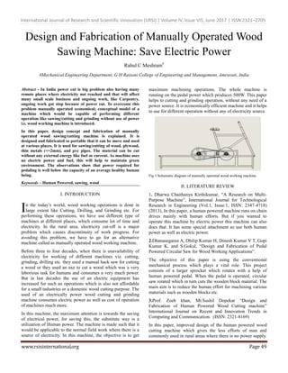
  • 1. International Journal of Research and Scientific Innovation (IJRSI) | Volume IV, Issue VIS, June 2017 | ISSN 2321–2705 www.rsisinternational.org Page 49 Design and Fabrication of Manually Operated Wood Sawing Machine: Save Electric Power Rahul C Meshram# #Mechanical Engineering Department, G H Raisoni College of Engineering and Management, Amravati, India Abstract - In India power cut is big problem also having many remote places where electricity not reached and that will affect many small scale business and ongoing work, like Carpentry, ongoing work got stop because of power cut. To overcome this problem manually operated economical; conceptual model of a machine which would be capable of performing different operation like sawing/cutting and grinding without use of power i.e. wood working machine is introduced. In this paper, design concept and fabrication of manually operated wood sawing/cutting machine is explained. It is designed and fabricated so portable that it can be move and used at various places. It is used for sawing/cutting of wood, plywood, thin metals (<=2mm), and pvc pipes. The material can be cut without any external energy like fuel or current. As machine uses no electric power and fuel, this will help to maintain green environment. The observations show that power required for pedaling is well below the capacity of an average healthy human being. Keywords – Human Powered, sawing, wood I. INTRODUCTION n the today’s world, wood working operations is done in large extent like Cutting, Drilling, and Grinding etc. For performing these operations, we have use different type of machines at different places, which consume lot of time and electricity. In the rural area, electricity cut-off is a major problem which causes discontinuity of work progress. For avoiding this problem, we have to go for an alternative machine called as manually operated wood working machine. Before three to four decades, when there is unavailability of electricity for working of different machines viz. cutting, grinding, drilling etc. they used a manual hack saw for cutting a wood or they used an axe to cut a wood which was a very laborious task for humans and consumes a very much power. But in last decades the use of an electric equipment has increased for such an operations which is also not affordable for a small industries or a domestic wood cutting purpose. The used of an electrically power wood cutting and grinding machine consumes electric power as well as cost of operation of machines much more. In this machine, the maximum attention is towards the saving of electrical power, for saving this, the substitute way is a utilization of Human power. The machine is made such that it would be applicable to the normal field work where there is a source of electricity. In this machine, the objective is to get maximum machining operations. The whole machine is running on the pedal power which produces 500W. This paper helps to cutting and grinding operation, without any need of a power source. It is economically efficient machine and it helps to use for different operation without any of electricity source. Fig 1 Schematic diagram of manually operated wood working machine. II. LITERATURE REVIEW 1. Dharwa Chaithanya Kirthikumar, “A Research on Multi- Purpose Machine”, International Journal for Technological Research in Engineering (Vol.1, Issue.1, ISSN: 2347-4718) (2013), In this paper, a human powered machine runs on chain drives mainly with human efforts. But if you wanted to operate this machine by electric power this machine can also does that. It has some special attachment so use both human power as well as electric power. 2.Dhanasegaran A, Dhilip Kumar H, Dinesh Kumar V T, Gopi Kumar K. and S.Gokul, “Design and Fabrication of Pedal Powered Circular Saw for Wood Working Applications”. The objective of this paper is using the conventional mechanical process which plays a vital role. This project consists of a larger sprocket which rotates with a help of human powered pedal. When the pedal is operated, circular saw rotated which in turn cuts the wooden block material. The main aim is to reduce the human effort for machining various materials such as wooden blocks etc. 3.Prof. Zoeb khan, Mr.Sushil Dopekar “Design and Fabrication of Human Powered Wood Cutting machine” International Journal on Recent and Innovation Trends in Computing and Communication. (ISSN: 2321-8169) In this paper, improved design of the human powered wood cutting machine which gives the less efforts of man and commonly used in rural areas where there is no power supply. I
  • 2. International Journal of Research and Scientific Innovation (IJRSI) | Volume IV, Issue VIS, June 2017 | ISSN 2321–2705 www.rsisinternational.org Page 50 The design ensures a smooth operation during the cutting process. It is light in weight and portable machine. III. DESIGN PROCEDURE A. Material selection The proper selection of material for the different part of machine is the main objective in the fabrication of machine. For a mechanical engineer it is must that he is familiar with the effect, which the manufacturing process and heat treatment have on properties of material. The choice of material for engineering purpose depends upon the following factors: 1. Availability of material. 2. Suitability of material for the working condition in service. 3. The cost of materials. 4. Physical and chemical properties of material. 5. Mechanical property of material. Table 4.1 Raw Material and Standard Material Used B. Design and modeling Specification of Manually Operated Wood Working Machine 1. Frame width = 67 cm 2. Frame length = 152 cm 3. Frame height = 128 cm 4. Area of frame = 10184 cm2 Specification of Transmission System 1. Driving sprocket = 60 teeth 2. Driven freewheel = 18 teeth 3. Driving freewheel = 14 teeth 4. Shaft length = 45 cm 5. Bearing diameter = 2.5 cm 6. Chain length = 58 cm 7. Seat height = 75 cm 8. Handle height = 81 cm 1. Design of Flywheel a) Calculation for Chain Drive: Sprocket Dia. = 24 cm = 240 mm D = dia. of pitch circle T = number of teeth on sprocket Find the pitch of chain Ө = = = 60 P = 2 X X P = 9.42 mm Velocity ratio of chain drive V.R. = = N1 = speed of rotation of freewheel in R.P.M. N2 = speed of rotation of sprocket in R.P.M. T1 = number of teeth on freewheel T2 = number of teeth sprocket V. R. = = = 3.33 The average velocity of chain is given by V= = V = 150.8 m/s b) Mass and Cross Section of Rim: Outer dia. of rim=500mm E=m*k2 *wn 2 *ks----------------------1 Where, K =radius of gyration=Dm/2 (Dm = Mean Diameter of Flywheel) Dm=0.9*Do Dm= 0.9*0.5=0.45m K=0.45/2=0.225m Wn = mean angular speed in rad/sec =2* *N/60 N=(750+650)/2=700rpm Wn = (2*3.14*700)60=73.30rad/sec From equation 1, 27=m*0.2252 *73.32 *0.02 M= 4.96Kg = 5Kg Assuming rim provides 95% of required moment of inertia E=0.95*I*Wn 2* ks I=0.2644Kg-m2 M=5.22Kg c) Rim Cross Section: Mass of rim=A*length*p M=A*3.14*Dm*Density Sr. No. Part Name Material Qty. 1 Square Pipe And Square Angle Iron 45ft 2 Pedestal Bearing C. I. and steel alloy 4 3 Sprocket Stainless Steel 1 4 Chain Alloy Steel 1 5 Pedal Cast iron 1 6 Freewheel Steel alloy 1 7 Grinding wheel Abrasive material 1 8 Cutting wheel Steel alloy 1 9 Bicycle frame Chromoly 1 10 Seat Rubber 1 11 Fastening ( Nut, Bolt, Washer ) Stainless Steel -
  • 3. International Journal of Research and Scientific Innovation (IJRSI) | Volume IV, Issue VIS, June 2017 | ISSN 2321–2705 www.rsisinternational.org Page 51 5.5=A* *0.45*7200 A=5.4*10-4 m2 If, b=2h……. b=breadth A=2h2 h=thickness h=0.03287m h=32.87mm b=2*32.87=65.8 mm Now, Do = Dm+h =450+32.87 Do=482.87mm d) Stresses in Flywheel: Tensile stress due to centrifugal force =P*Vs 2 Vs.= Surface speed π*DoN =7200*[(3.14*0.5*700)/60]2 =2.25mpa Stress due to bending of rim =(3.14*Vs*p*DO)/I2 *h I=no. of arms I=6 ……..(300<DO<400mm) =(π*313.13*7200*0.48280)/(62 *0.03287) =9.07mpa e) Resultant Stresses : =0.756 +0.25 =0.75*2.25+0.25*9.07 Stress=3.955Mpa<allowable stress for C.I. =140mpa Therefore design is safe. f) Flywheel Construction Details: a) Hub dia.(Dh)=2d=3=2*30=60mm b) Length of hub(lh)=2.25d =2.5*30=75mm g) Total Weight of Flywheel: Area of hub (A)=(π/4)*(Dh 2 -ds 2 ) =(3.14/4)*(602 -302 ) =2.12*10-3 m2 Volume of hub(V)=A*Lh = 2.12*10-3 *0.075 V=1.59*10-4 m-3 Mass of hub(Mh)=V*density =1.59*10-4 *7200 Mh=1.145Kg Total weight of flywheel =mass of rim+mass of hub+mass of arm =5.5+1.145+0.5 =7.145Kg Total weight of flywheel=7.145Kg 2. Design of Shaft a). Assumption: 1) The shaft is considered as a simply supported beam 2) Material used for shaft is (SAE)1030 b) Reaction Calculation : Weight of flywheel (approximately)=70N Pulley if Diameter= 30 cm Pulley Radius=6’’=152.5mm Diameter of sprocket=63mm Distance of paddle from center of larger sprocket=0.18m Torque which is getting by pedaling, Torque=Force*Distance =300*0.18 =54Nm Tension in the belt, T1=(54/2)/0.1525 =177N Pitch circle radius of larger sprocket=0.1m Total tension in the chain, T2=54/0.1=540N c) Vertical Force Diagram: RAV and RFV are vertical reaction support at support A& F resp. Reaction at RA and RF RA+RF=25+20+70=115N--------------1 Taking moment about A, ∑MA=0 RAV*0.5=25*0.15+20*0.25+70*0.30 RAV=59.5N RAV+59.5=115 RAV=55.5 d) Vertical Bending Moment Calculation: Bending moment at A=0 Bending moment at F=0 Bending moment at E=59.5*0.05=3Nm Bending moment at D = 59.5*0.2 = 11.9 Nm Bending moment at C=59.5*0.25-70*0.05=11.37Nm Bending moment at B=55.5*0.15=8.32Nm e) Horizontal Force Diagram: RAV+RFH are horizontal reaction at support A & F resp. RAV+RFH=200+540 =740N------------------2 Taking moment about A, ∑MA=0 RFH*0.5=540*0.45+200*0.15 RFH=546N Equation 2 -
  • 4. International Journal of Research and Scientific Innovation (IJRSI) | Volume IV, Issue VIS, June 2017 | ISSN 2321–2705 www.rsisinternational.org Page 52 RAH+546=740 RAH=194 N f) Horizontal Bending Moment Calculation: Bending moment at A=0 Bending moment at F=0 Bending moment at E=546*0.05 =27.3Nm Bending moment at D=546*0.2-540*0.15 =28.2Nm Bending moment at C=546*0.25-540*0.2 =28.2Nm Bending moment at B=546*0.35-540*0.3 =29.1N g) Resultant Bending Moment Calculation Resultant bending moment at B= = 30.26Nm Resultant bending moment at C= = 30.68Nm Resultant bending moment at D= = 30.60Nm Resultant bending moment at E= = 27.46Nm Selecting maximum bending moment=30.68Nm According to nature of loading, selecting constant for shaft design For rotating shaft, Suddenly applied load (Minor shock) Kb=1.5, Kt =1 Where Kb&Kf are constant for bending moment and torsion resp. Selectingshaft material SAE 1030. Syt= 296 Mpa,Sut=527 Mpa Where Syt= Yield stress. Sut=ultimate stress. Tmax= maximum shear stress. Allowable shear stress, Tmax=0.3Syt 0.18 Sut =0.3*296 or 0.18*527 =88.8 Mpa or 94.86 Mpa Considering key way effect Tmax=0.75*88.8 =66.5 Mpa Shaft diameter is given by, For solid shaft, Tmax= {(16/π*d3 )*{(Kb*Mmax) 2+ (Td*Kt)2 } 66.6*106 = {16/3.14*d3 }*{(1.5*30.68)2 + (54)2 d =0.0176m =17.6 mm Selecting next standard higher value=20mm So, diameter of shaft=20mm 3. Design of V-Belt Drive Data Pr=Rated power =0.565 kW. N1=500rpm N2 = 1500 rpm C= Center distance=500mm a) Design Power: Pd=Pr*K1 Where, K1= load factor =1.10 Pd=0.565*1.10=0.6215 kW. Selecting section of belt on basis of design power From data book =w=13 Nominal thickness=8mm Recommended min pulley diameter =75mm b) Peripheral Velocity (Vp): Selecting diameter of smaller pulley as 75 mm VP =3.14*D2*N2/1000 =3.14*75*1500/1000 =355m/min Since Vpis in the range of 300-1500m/min. c) Tension Ratio: Due to wedging action in v-belt slip is negligible small hence we can write, N2D2=N1D1 1500*75=500*D1 D1=225mm Angle of lap on smaller pulley ( ) =3.14-{D1-D2)/c}= -{(225-75)/500} =0.3 Angle of lap on larger pulley( ) θ =3.14+{D1-D2)/c}=3.14{(225-75)/1500} =3.44 Since value for smaller pulley is less hence smaller pulley governs the design, F1/F2=e0.3*angle of lap*cosec*α/2 Where, Groove angle=38’ Coefficient of friction=0.3 F1/F2=e0.3*0.3*cosec38/2 -----------------------------------------1 =1.31 (F1—F2)=Pd/Vp =(0.6215*103 *60)/355 =105N _________________2 From equation 1 &2
  • 5. International Journal of Research and Scientific Innovation (IJRSI) | Volume IV, Issue VIS, June 2017 | ISSN 2321–2705 www.rsisinternational.org Page 53 F2=338.7N F1=443.7N d) Power Capacity per Belt: Power belt=(FW-FC)*(e0.3*0.3*cosec*38/2 -1/e0.3*0.3cosec*38/2 )*VP Where, FW=Working load= w2 =132 =169N FC=Centrifugal tension Fc=Kc*(VP/5)2 Kc=Tension Factor = 2.52 VP= 5.9 m/sec. FC=3.5N Power/ belt=(169-3.59)*e0.30.3cosec*38/2 -1/e0.3*0.3cosec38/2 )*5.9 =235.6w =0.235kw e) Length of Belt: L=π/2*(D1+D2)+2C+(D1-D2)2 /4C =3.14/2*(225+75)+2*500)+(225-75)2 /(4*500) L=1482.5mm f) Shaft Design: Selecting shaft material as SAE 1030, for which Syt=296Mpa. From maximum shear stress theory, Tmax=Syt/2*FS---------------------(FS=2.5) =296/(2*2.5) Tmax=59.2Nmm From data book design torque for shaft Td=60*Pr*K1/2*π*N1 =(60*0.565*103 *1.5)/2*3.14*500---------------K1=load factor =1.5 for line shaft Td=16.18N-m Tma=16*Td/3.14d3 d3 =(16*16.18*103 )/(π*59.2) d=11.16mm In order to consider the bending effect, diameter is increased by 50% hence d =11.16*1.5=16.75mm Select standard shaft diameter, d =20mm g) Pulley Hub Proportions : Hub diameter =Dh=1.5d+25=1.5*20+25=55mm Hub length=Lh=1.5d=1.5*20=30mm h) Arm Cross Section: Moment of each arm M=(F1-F2)*(D1-Dh)/n -------------n=no of arms =(443.7-338.7)*(225-55)/6 M=2975 N-mm M=2.975 N-m Assuming elliptical cross section for arm, Section modulus for elliptical cross section is Z=π*h3 /64 ------------------(h=major axis=2*minor axis.) Allowable stress in bending for cast iron with steady load, Bending stress=15 Mpa. Bending stress=M/Z Z=M/Bending stress =3.14/64=2975/15h=15.92mm say 16mm IV. MODELING AND FABRICATION A. Modeling of Wood Working Machine Modeling of the machine components and assembly has been done by using Solid Work Software. a) Frame: Fig. 2 Frame Frame plays a very important role in any machine, because it holds all the working part. All the parts are perfectly mounted on the frame. Generally M.S. pipe having rectangular cross- section is used for the frame. In this machine we will going to use light weighted and rigid frame. The base area required for this frame is 6x4 feet. b) Flywheel: Fig. 3 Flywheel A flywheel is an inertial energy-storage device. It absorbs mechanical energy and serves as a reservoir, storing energy during the period when the supply of energy is more than the requirement and release it during the period when the requirement of energy is more than the supply. The main function of a flywheel is to smoothen out variation in the speed of a shaft caused by fluctuations. If the source of the driving torque or load torque is fluctuating in nature, then a flywheel is usually called for. Many machines have load
  • 6. International Journal of Research and Scientific Innovation (IJRSI) | Volume IV, Issue VIS, June 2017 | ISSN 2321–2705 www.rsisinternational.org Page 54 patterns that cause the torque time function to vary over the cycle. c) Shaft: Fig. 3 Shaft A shaft is a rotating machine element which is used to transmit power from one place to another. The power is developed to the shaft by some tangential force and the resultant torque (or twisting moment) set up within the shaft permits the power to be transferred to various machines linked up to the shaft. In order to transfer the power from one shaft to another, the various members such as gear, pulleys etc., are mounted on it. These members along with the forces exerted upon them causes the shaft to bending. In other words, we may say that a shaft is used for the transmission of torque and bending moment. The various members are mounted on shaft by means of keys. Fig 4 Front view Assembly Fig 5 Side View Assembly Fig 6 Top View Assembly Fig 7 Isometric View B. Fabrication of Wood Working Machine Fabrication is the process of assembly of various parts. It includes operations such as cutting, grinding, drilling, turning, threading etc. with the help of different machines. a) Frame We have fabricated frame from rectangular and square tube. The base was made by rectangular cross-section of tube of dimensions 1”x2” and square cross-section of tube of dimensions 1”x1”. Firstly we cut the tubes according to our dimensions then grind it for removing burr from it. Then we welded the tubes together by using Arc Welding. Dimensions of frame – 6.2”x48”x12”. Fig. 8 Frame of a Machine b) Bicycle Frame
  • 7. International Journal of Research and Scientific Innovation (IJRSI) | Volume IV, Issue VIS, June 2017 | ISSN 2321–2705 www.rsisinternational.org Page 55 Bicycle frame was mounted on the Base frame by Arc welding. According to our suitable dimensions of design. The bicycle frame should be vertical in position it should be rigid. So as to avoid accidents. The handle of circular pipe was welded to the bicycle frame by considering the appropriate position of sitting. Height of handle from ground is 96cm and distance between operator seats to ground level is 102cm. Fig. 9 Bicycle Frame C) Circular Shaft There are two shafts, which are having different purpose. Primary shaft (large in length) is attached to rear end of the bicycle sprocket. Which is run by the chain drive. It consist of a balanced flywheel at some distance from one end and driving pulley attached at other end bye a belt drive. The secondary shaft is attached to the base frame. The secondary shaft consist of blade and driven pulley which is rotated by primary shaft by a belt drive. As per design requirement step turning and threading operation perform on the circular solid MS shaft on Lathe machine. Shaft dimensions are 25 mm in diameter and cm (primary shaft), 20 mm diameter and 62 mm in length. Fig. 10 Circular Shaft (large shaft) Fig. 11 Circular Shaft (Small Shaft) d) Wood Cutting Platform Wood cutting platform made up of Square tube. Dimensions are 43x60 cm. a plywood of having 8mm thickness and same dimensions of platform fastened by using fasteners to the wood cutting platform. Fig. 12 Wood Cutting Platform These above parts of manually operated wood working machine are made by C. Assembly Wood Working Machine The arrangement of various component of “Manually Operated Wood Working Machine” is being done are as follows: 1. The foundation frame is being selected which carry the entire load of the machine. 2. The transmission system mounted on the base of frame. 3. The sprocket is connected to driven freewheel with the help of chain. 4. The freewheel shaft is mounted on the base of the foundation frame with the help of pedestals bearing which is fasten using nut and bolt. This shaft is connected to the driving freewheel of roller. 5. The roller shaft is mounted on the top face of the foundation frame with the help of pedestals bearing which is fasten using nut and bolt. This shaft is driven with the help of freewheel and chain connection. 6. The cutting wheel fixed on the rotating shaft at middle portion. And at the end of this shaft grinding
  • 8. International Journal of Research and Scientific Innovation (IJRSI) | Volume IV, Issue VIS, June 2017 | ISSN 2321–2705 www.rsisinternational.org Page 56 wheel is attached by using fastener for grinding operation. 7. Platform to place and moving of a wood fix on the main frame. It is fastened to the frame by using nut and bolt arrangement. 8. The platform taken above some height of main shaft and bellow to rotating cutter. The above arrangement ensure that all element of the project are balanced and also center of gravity of the assembly is on axis. Fig. 13 Wood Cutting Machine Assembly V. ADVANTAGES 1. It required no power for operation. 2. It is easy in maintenance. 3. It does not require any special skill for operation. 4. Cost of manually operated wood working machine is less than other machines because no source of electricity required. 5. Its construction is simple. VI. DISADVANTAGES 1. For working operations, it needs two people to work on machine at a time. 2. It is time consuming but cheap process. 3. It require human effort for operating cutting machine. 4. Sometimes the small groundnut does not break. VII. APPLICATION 1. It can be used in small carpentry workshop. 2. It is use for cutting wood where power source not available. 3. In rural areas where electricity cut-off problems occurs. 4. It is use for grinding operation. VIII. CONCLUSION Proper evaluation of the design will be performed and created something even better instead of electrically operated operations. Finally we conclude that this machine is better option to use for Carpenter. Thus a low cost and simple design pedal operated wood working machine is fabricated. This machine reduces the human effort and hence we need two persons to cut the wooden logs. This simple design of conventional design which can enhance day-to-day household needs and day-to-day purposes and it can be also used in for industrial applications during power shut down scenarios. By using this method we can do Cutting and grinding operation without the use of electricity. So we can save the electrical power. Experimental result shows cutting depth of about 10 mm can be obtained can be obtained in one cycle of strokes for around 100rpm. The ply wood can be cut without any external energy like fuel or current. Since it uses no electric power and fuel, this is very cheap and best. The manually operated wood working machine by using pedal is easy to use hence does not require any skilled person. It is operated by pedaling action hence ensures comfort as compared to hand operated machines. REFERENCES [1]. Dharwa Chaithanya Kirthikumar, “A Research on Multi-Purpose Machine”, International Journal for Technological Research in Engineering (Vol.1, Issue.1, ISSN: 2347-4718) (2013). [2]. Dhanasegaran A, Dhilip Kumar H, Dinesh Kumar V T, Gopi Kumar K. and S.Gokul, International Journal of Current Engineering and Technology. “Design and Fabrication of Pedal Powered Circular Saw for Wood Working Applications”. [3]. Prof. Zoeb khan, Mr.Sushil Dopekar, ”Design and Fabrication of Human Powered Wood Cutting machine” International Journal on Recent and Innovation Trends in Computing and Communication. ISSN: 2321-8169. [4]. J.P. Modak and R. D. Askhedkar, “Hypothsis for the Extrusion of lime flash sand bricks using a manually driven bricks making machine”, Building Research and Information, 22 (1); 47-54 [5]. Machine design and drawing by R.S. Khurmi and J.K. Gupta, S. Chand publications.