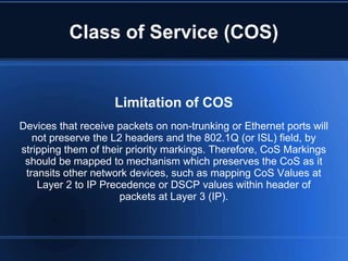
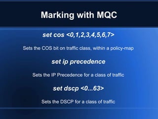
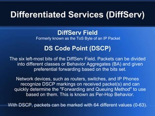
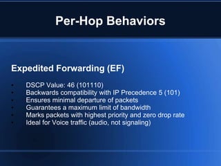
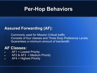
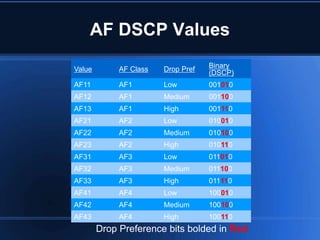
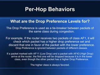
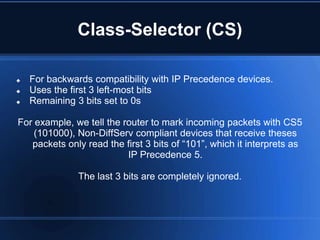
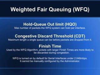
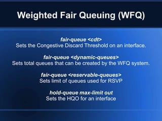
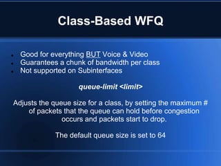
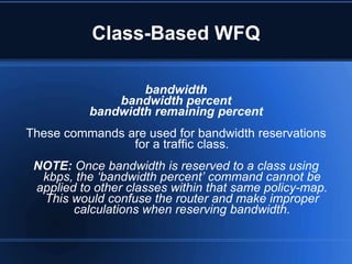
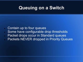
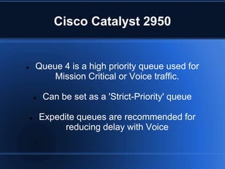
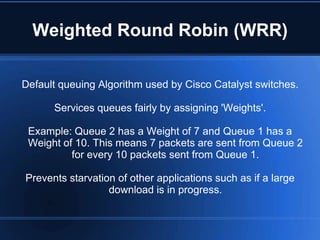
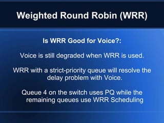
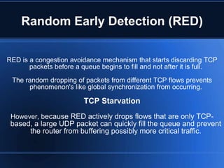
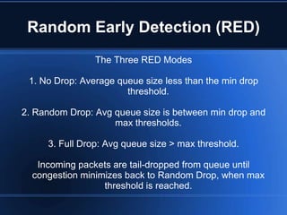
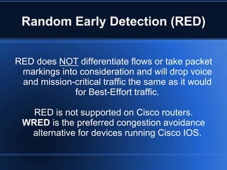
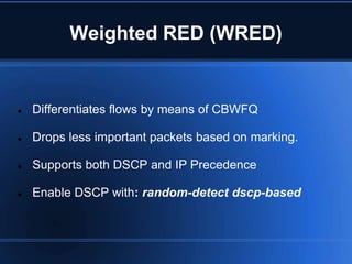
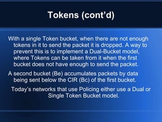
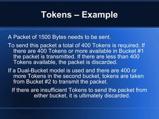
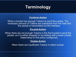
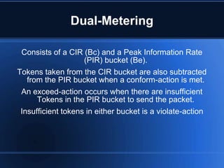
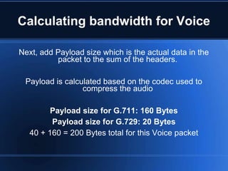
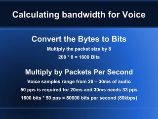
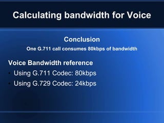
This document provides an overview of Cisco Quality of Service (QoS) methods and configuration. It discusses legacy CLI, Modular QoS CLI (MQC), and AutoQoS features for implementing QoS policies. It also covers traffic classification, marking, queuing mechanisms like weighted fair queuing (WFQ) and low-latency queuing (LLQ), and configuration of QoS on switches.
This document discusses quality of service (QoS) techniques for prioritizing different types of network traffic such as voice over IP. It describes several QoS mechanisms including weighted fair queuing, priority queuing, class-based weighted fair queuing, IP precedence, policy routing, and resource reservation protocol. These mechanisms allow administrators to classify and manage network traffic to ensure sufficient bandwidth and latency for applications like VoIP that have sensitive network requirements.
This document provides an introduction to fundamentals of quality of service (QoS) in computer networks. It defines key QoS metrics like bandwidth, latency, jitter and packet loss. It describes the DiffServ model where packets are marked to indicate required QoS and network devices apply QoS based on these markings. It also discusses signaling QoS requirements using markers like Type of Service, Class of Service and DSCP. It covers topics like per-hop behavior, configuration of class maps and policy maps, queuing and discard algorithms, and traffic shaping algorithms like leaky bucket and token bucket.
This document discusses quality of service (QoS) classification on Cisco IOS routers. It explains that applications like voice have different network requirements than bulk file transfers. To ensure each application gets proper treatment, traffic must be classified. Classification methods on IOS routers include header inspection of fields like ports and IP addresses, and deeper payload inspection using Network-Based Application Recognition (NBAR) which can identify applications regardless of port. The document demonstrates simple classification using an access control list matched to a class map in a policy map applied to an interface. It also shows classification using NBAR to match protocols like Telnet in a class map.
This slide contains fundamental concept about Quality of Service (QoS) technology and various types of Queuing Methods, according to the latest version of Cisco books (CCIE R&S and CCIE SP) and i taught it at IRAN TIC company.
This document discusses configuring QoS marking on a Cisco IOS router. It shows how to mark telnet traffic with IP precedence 7 and HTTP traffic with DSCP AF12 by creating access lists, class maps, and a policy map. It also demonstrates verifying the marked packets are received correctly by matching on the markings at the destination router.
1. The document discusses some challenges with deploying QoS in the University of Pennsylvania network and the MAGPI GigaPoP, which provides connectivity between universities.
2. Key challenges include immature router support for QoS features, lack of inter-domain signaling mechanisms, and ensuring QoS changes don't disrupt existing production traffic.
3. For the time being, efforts focus on facilitating QoS experimentation for researchers without impeding other traffic, such as providing uncongested paths through the network.
The presentation covered bandwidth management and quality of service (QoS) techniques in MikroTik RouterOS, including mangle rules to mark traffic, hierarchical token bucket (HTB) queue structures, and different queue types. Mangle rules are used to identify traffic by protocol, port, or address and mark it for further processing. HTB implements hierarchical queues that can set committed and maximum rates. Queue types include simple queues for easy bandwidth limiting and queue trees for priority-based queuing of pre-marked traffic. The talk provided examples and explanations of how to implement these QoS features in RouterOS for bandwidth control and prioritization of different traffic classes.
Introduction of PS Core Network Elements and little bit of EPC/LTE Network. This is introductory slides pack for a 10 class/slides set for detail introduction of 2G/3G and LTE PS Core Network.
This document provides an overview and agenda for a presentation on VXLAN BGP EVPN technology. It begins with an introduction to VXLAN and EVPN concepts. It then outlines the agenda which includes explaining VXLAN configuration, EVPN configuration, underlay configuration, overlay configuration, and EVPN VXLAN service configuration. It also provides a sample migration from a legacy device configuration to a VXLAN BGP EVPN configuration. Various networking acronyms related to VXLAN and EVPN are defined. Sample vendor supported data center technologies and a VXLAN test topology are shown.
The document discusses Ethernet, spanning tree protocol, WiFi, and IP version 4. It provides details on Ethernet frame formats, Ethernet switches and how spanning tree protocol elects a root switch and handles failures. It also describes WiFi standards, channel frequencies, and 802.11 frame formats. Finally, it summarizes the fields in an IP version 4 packet header.
In This Presentation, Following Topics for PCRF basic, with details of E// SAPC, are clarified and presented.
SAPC definition
Functional View
Service Aware Policy Control
Bearer Resource Control
Cross Control Functions
Information Model and O&M
Platform
BGP Flowspec (RFC5575) Case study and DiscussionAPNIC
BGP Flowspec is a technique for distributing flow specification rules via BGP. It allows an ISP to dynamically distribute filtering and redirection rules to mitigate DDoS attacks. The document discusses several real-world use cases where BGP Flowspec was deployed to successfully block large DDoS attacks in a targeted manner without affecting legitimate traffic. However, interoperability between vendors and scalability challenges remain open issues requiring further work and testing.
The document discusses Virtual Private Routed Network (VPRN) services. VPRNs use BGP and MPLS to provide Layer 3 VPN connectivity between customer sites. Each VPRN has its own routing table maintained by provider edge (PE) routers. PE routers exchange routes for each VPRN using MP-BGP. Routes include a Route Distinguisher to identify the VPRN. Tunnels using MPLS or GRE carry customer traffic across the provider network to the correct PE router based on the route label. The document outlines requirements, protocols, and features used to implement VPRNs such as route reflectors, route redistribution, and CE connectivity checks.
IPv6 Segment Routing is a major IPv6 extension that provides a modern version of source routing that is currently being developed within the Internet Engineering Task Force (IETF). We propose the first open-source implementation of IPv6 Segment Routing in the Linux kernel. We first describe it in details and explain how it can be used on both endhosts and routers. We then evaluate and compare its performance with plain IPv6 packet forwarding in a lab environment. Our measurements indicate that the performance penalty of inserting IPv6 Segment Routing Headers or encapsulat- ing packets is limited to less than 15%. On the other hand, the optional HMAC security feature of IPv6 Segment Routing is costly in a pure software implementation. Since our implementation has been included in the official Linux 4.10 kernel, we expect that it will be extended by other researchers for new use cases.
Presented at ANRW'17 https://irtf.org/anrw/2017/program.html on behalf of David Lebrun
Presentation given at MPLS+SDN+NFVWORLD 2019 in Paris that shows how network architects can leverage the support for IPv6 Segment that is included in the Linux kernel to develop new end-to-end services that use IPv6 Segment Routing on clients, routers and servers.
MPLS (Multi-Protocol Label Switching) is introduced as a "Layer 2.5" protocol that sits between traditional Layer 2 and Layer 3 networking. It works by assigning labels to packets at ingress routers and using those labels for fast forwarding decisions without additional routing lookups at subsequent routers. This improves performance over traditional IP routing. MPLS also enables traffic engineering through protocols like RSVP-TE that allow reserving bandwidth on specific paths. Other key MPLS concepts covered are label switching, MPLS signaling protocols, label stacking, pseudowires, VPN services, and fast reroute for improved convergence during failures.
The document discusses routing protocols in IP networks and interdomain routing. It provides an overview of IPv6 neighbor discovery, routing protocols RIP and OSPF, and interdomain routing with BGP. Key concepts covered include how routers discover each other on the local link, distance vector and link-state routing, using areas in OSPF, and the path vector exchange in BGP to choose optimal routes between autonomous systems.
BGP Flow Specification allows network operators to define and distribute traffic filtering rules via BGP. This helps operators quickly mitigate DDoS attacks by filtering traffic at an upstream level rather than just blackholing entire prefixes. It separates filtering information from routing data using new BGP address families. Validating flow specifications against the best unicast route helps prevent spoofing. Common filtering actions include traffic policing, sampling, and redirection. While some ISPs have begun implementations, widespread adoption is still needed to realize the benefits of centralized DDoS defense using BGP Flow Specification.
The document discusses making networking stacks more extensible through the use of eBPF programs. It describes how eBPF can be used to program IPv6 segment routing, make TCP more customizable through hooks in the stack, and allow routing protocols to be extended through plugins. Examples are given of using eBPF to add monitoring to TCP and implement flexible filtering in BGP. The performance impact of eBPF programs is shown to be minimal compared to native code implementations.
Part 10 : Routing in IP networks and interdomain routing with BGPOlivier Bonaventure
This document discusses routing in IP networks and interdomain routing with BGP. It begins by covering intradomain routing protocols like RIP and OSPF, then discusses interdomain routing and the exterior gateway protocol BGP. BGP allows domains to exchange routing information and select paths between domains while applying each domain's routing policies.
This slide contains the basic and advanced concept of OSPF routing protocol, according to the latest version of Cisco books, and I presented it at IRAN TIC company. In the next slide, I will upload an attractive advanced feature about OSPF.
The document discusses the SIGTRAN protocol stack and its components SCTP and M3UA. It provides an overview of these protocols, including their objectives, features, message structures, and functions in transferring SS7 signaling over IP networks. Key concepts discussed include SIGTRAN layers, SCTP transmission addressing, association establishment and termination, and M3UA routing, entities, and message transfer procedures.
The document discusses the Gateway Load Balancing Protocol (GLBP). GLBP allows multiple routers to share the traffic load and act as redundant gateways for hosts on a LAN. One router is elected as the active virtual gateway (AVG) to forward traffic and respond to ARP requests. Other routers are designated as active virtual forwarders (AVFs) and each assumes responsibility for forwarding traffic to a different virtual MAC address. This provides load sharing and redundancy if an AVG or AVF fails.
GLBP (Gateway Load Balancing Protocol) is a Cisco proprietary protocol that attempts to overcome the
limitations of existing redundant router protocols by adding basic load balancing functionality. GLBP is a
virtual gateway protocol similar to HSRP and VRRP.
However, unlike its little brothers, GLBP is capable of using multiple physical gateways at the same time.
As we know, a single HSRP or VRRP group represents one virtual gateway, with single virtual IP and MAC
addresses. Only one physical gateway in a standby/redundancy group is responsible for packet
forwarding, others remain inactive in standby/backup state.
This document describes an ISP core routing topology project that was implemented to demonstrate how a company accesses its servers through the internet. The key features of the project include MPLS Layer 3 VPN, an IPv6 network with an IPv6 DNS server, various redundancy protocols like HSRP, VRRP and GLBP, dynamic routing protocols such as BGP, EIGRP and OSPF, and a Linux server providing services like DNS, Apache, FTP and SSH. MPLS is used to eliminate delays and provide a VPN connecting different company branches. The topology also features an IPv6 tunnel over an IPv4 network and dual stacking for IPv6/IPv4 communication.
This document discusses quality of service (QoS) capabilities in OpenStack Neutron. It provides an overview of what QoS means for networks, what is currently supported in Neutron, and how to use Neutron's QoS features. It also describes how QoS works underneath with different agent types and plans for future enhancements, including better rule validation, ingress bandwidth limiting, and integration with Horizon. Regular QoS meetings in the Neutron community discuss ongoing work.
This document provides instructions for configuring packet capture on a Cisco ASA firewall. It describes using the packet capture wizard in ASDM or CLI commands to define a capture named "capin" on the inside interface and "capout" on the outside interface. The capture filters use access lists to match traffic between the inside and outside networks. The show capture command can then be used to view the captured packets.
This document provides an overview and study guide for the CCIP MPLS exam. It discusses key MPLS concepts like label distribution, label switching, and MPLS VPNs. The exam tests knowledge of MPLS fundamentals, frame and cell mode MPLS, MPLS VPN implementation, complex MPLS VPNs, and internet access from an MPLS VPN. It provides details on topics covered in the exam and guidance on how to prepare.
Intro to Single / Two Rate Three Color Marker (srTCM / trTCM)Kentaro Ebisawa
The objective of this document is to provider entry point for people to understand srTCM and trTCM (single / two rate Tree Color Marker).
This document will explain algorithm described in below RFCs, and compare two different algorithm used for trTCM.
RFC 2697 - A Single Rate Three Color Marker
RFC 2698 - A Two Rate Three Color Marker
RFC 4115 - A Differentiated Service Two-Rate, Three-Color Marker with Efficient Handling of in-Profile Traffic
Regular expressions are strings that define patterns to match character sequences. They can be used in Cisco IOS show commands and AS-Path access-lists to match BGP prefixes based on AS-Path information. Regular expression characters have specific meanings, such as ^ and $ to match the start and end, [] for ranges, and * + ? for quantity. An example expression matches routes originated from directly connected ASes or their customers by representing AS numbers as "X" and using quantity symbols to account for multi-digit ASNs.
This document discusses troubleshooting basic BGP connectivity between two sites. It describes the three tables that BGP connectivity is built upon: the neighbor table showing BGP session state, the BGP table learning prefixes, and the IP route table selecting best routes from the BGP table based on attributes like weight, local preference, AS-path length. The document also states that a candidate with BGP knowledge should be able to accurately describe connectivity between two sites using BGP.
Firewalls work by denying or permitting network traffic based on configured policies. A firewall protects internal networks from unauthorized external access and can also separate internal networks. Stateful firewalls are aware of network connections and maintain related information in a connection table, while stateless firewalls make decisions based only on individual packets.
The document discusses quality of service (QoS) in multimedia communication networks, including QoS parameters and classes, deterministic and predictive QoS parameters, guaranteed and best effort QoS, QoS-aware service models, scheduling and policing mechanisms like priority scheduling and weighted fair queueing, and QoS architectures like Integrated Services and Differentiated Services.
When I first started as a sales person in the gym business, I was terrible. Every Monday when the sales standings would come out for the 4 clubs, I was dead last. I was so uncomfortable in the sales process, my mouth would actually get so dry that I could barely get any words out.
The document discusses Quality of Service (QoS) techniques used to prioritize certain types of network traffic over others. It covers QoS concepts like classification, marking, queuing, and congestion avoidance. It also provides examples of how to implement QoS in Cisco devices and deploy QoS enterprise-wide.
This document discusses Quality of Service (QoS) in converged networks. It describes how traffic characteristics have changed with converged networks, bringing together constant small-packet voice flows and bursty data flows. This requires that critical traffic like voice and video be prioritized to address issues like delays, jitter, and packet loss. The document then discusses various factors that can cause these quality issues, such as lack of bandwidth, end-to-end delay, jitter, and packet loss. It proposes different QoS mechanisms to classify traffic, prioritize time-sensitive traffic, and prevent congestion including IntServ, DiffServ, traffic policing, shaping, queuing techniques, and dropping policies. The goal is to apply these techniques to
The BTS3900B supports quality of service (QoS) priority by mapping service priority to both the IP and data link layers. At the IP layer, it uses Differentiated Services Code Point (DSCP) values to denote priority, with higher DSCP values indicating higher priority. At the data link layer, it uses 802.1P/Q VLAN tagging and priority bits to classify frames by service type and priority level. This dual-layer mapping allows the BTS3900B to transfer packets with different QoS needs over the IP network.
Fundamental of Quality of Service(QoS) Reza Farahani
This slide contains fundamental concept about Quality of Service (QoS) technolog, according to the latest version of Cisco books (CCIE R&S and CCIE SP) and i taught it at IRAN TIC company.In the next slide, i upload advanced topic about this attractive technology.
This document discusses quality of service (QoS) models and mechanisms at different layers of the network. It provides information on common QoS markings like IP Precedence, DSCP, and 802.1p. It also describes different queuing mechanisms like priority queuing, weighted fair queuing, class-based weighted fair queuing, and low latency queuing. Key terms related to QoS like per-hop behavior, traffic policing and shaping are also defined.
Relatore: Alessandro Legnani, Cisco CCIE e IP Network Architect di IT Global Consulting Srl
Sintesi e sinergia perfetta di un nuovo protocollo di routing (e non solo) con il caro vecchio e robusto IPsec (senza le problematiche ike). Perché inventarsi l’ennesima forma di tunnelig per il data plane?
Quanto sopra è la chiave del successo della soluzione sdwan Cisco/Viptela che la rende enormemente scalabile e unica sul mercato.
The document discusses QoS models and differentiated services model features. It provides an overview of MPLS QoS, including mapping IP precedence to MPLS experimental bits, supporting DiffServ over MPLS using E-LSPs and L-LSPs, and examples of configuring MPLS QoS on PE routers including classification, policy maps, and attaching policies to interfaces.
MPLS Class of Service enables network administrators to provide differentiated types of service across an MPLS network. It offers packet classification, congestion avoidance, and congestion management. MPLS CoS lets you duplicate Cisco IOS IP CoS (Layer 3) features in MPLS devices, including label edge routers, label switch routers, and asynchronous transfer mode LSRs. Configuration involves setting up packet classification, weighted fair queueing, and weighted random early detection on interfaces and virtual circuits to provide differentiated services.
ccna summer training ppt ( Cisco certified network analysis) ppt. by Traun k...Tarun Khaneja
This document provides a summary of a presentation on CCNA (Cisco Certified Network Associate). It was trained by Ravinder Kumar from Gurukul Technical Institute and submitted by Tarun Khaneja with roll number 2110045 and contact number 09034406598. The presentation introduces CCNA and discusses networking types and applications. It also covers networking devices, subnetting, routing protocols like RIP, EIGRP, OSPF, ACLs, VLANs, and inter-VLAN routing. Configuration examples are provided for EIGRP and RIP routing on the same network.
The document discusses quality of service (QoS) concepts including why QoS is needed, QoS architecture models, components, configurations, queuing examples, and IOS commands. Specifically, it provides details on differentiated services (DiffServ) model, classification and marking, traffic conditioning, congestion management using class-based weighted fair queueing (CB-WFQ) and low latency queueing (LLQ), and the modular QoS command-line interface (MQC) for basic QoS configuration.
This document provides an overview of MPLS (Multi-Protocol Label Switching). It discusses the basic idea behind MPLS, the history and components. MPLS assigns labels to IP flows to create label switched paths between ingress and egress routers. Routers forward packets based on lookups of these labels rather than long IP addresses. MPLS supports traffic engineering and quality of service across networks while integrating technologies like IP, ATM, and Frame Relay.
This document provides a summary of a presentation on CCNA (Cisco Certified Network Associate). It includes:
1. An introduction to CCNA, which stands for Cisco Certified Network Associate and provides information about networking, its types and applications. Networking is important for communication and resource sharing.
2. Descriptions of different types of networking including LAN, MAN, and WAN. It also lists common networking devices like LAN cards, bridges, hubs, switches, and routers.
3. Overviews of topics covered in CCNA including subnetting, supernetting, Classless Interdomain Routing (CIDR), the differences between hubs and switches, what routers are used for,
The document provides an overview of IT network design and installation topics covered in a MaxWiFi training course, including network models, IP addressing, NAT, routing, DHCP, VLANs, wireless networking, and Cisco device configuration.
The document discusses QoS models and implementation techniques. It describes IntServ and DiffServ models, with IntServ providing guaranteed service but limited scalability, and DiffServ providing "almost guaranteed" service while being more scalable. It then covers classification and marking tools, congestion avoidance/management tools, and techniques like traffic shaping, policing, queueing strategies, and trust boundaries.
The document discusses QoS models and implementation techniques. It describes IntServ and DiffServ models, with IntServ providing guaranteed service but limited scalability, and DiffServ providing "almost guaranteed" service while being more scalable. It also covers classification and marking tools, congestion avoidance/management tools, and techniques for traffic marking including using VLAN, IPv4 ToS, IPv6 traffic class, and DiffServ code points.
This chapter discusses wide area network (WAN) technologies including HDLC, PPP, Frame Relay, and virtual private networks (VPNs). It defines WAN terminology and components. PPP is described as a protocol used to transport network layer packets over point-to-point links. Frame Relay is introduced as a high-performance WAN protocol that uses virtual circuits to transmit data between network devices. Finally, VPNs are summarized as secured connections used for remote access, site-to-site networking, and business partnerships over public networks like the Internet.
This chapter discusses wide area network (WAN) technologies including HDLC, PPP, Frame Relay, and virtual private networks (VPNs). It defines WAN terminology and components. PPP is described as a protocol used to transport layer 3 packets across point-to-point links. Frame Relay is introduced as a high-performance WAN encapsulation method that provides a connection-oriented data link layer. VPNs allow remote access, site-to-site, and extranet connectivity over public networks like the internet.
- OSPF is a link-state routing protocol that is more scalable than RIP. It builds a complete "map" of the network to avoid routing loops.
- OSPF uses link-state advertisements and flooding to exchange routing information between routers. It elects a designated router and backup designated router to optimize this exchange.
- Routers using OSPF establish neighbor relationships, synchronize their link-state databases, and calculate the shortest path to all known destinations using an algorithm on the link-state database.
CCNA ppt designed on project remote connectivity using frame relay, and many more... best for project purpose. anyone want project will also contact me..
OSPF Beyond Stump-the-Chump_Interview_Questions - Part 01 -Duane Bodle
This presentation is meant to help other network engineers to understand and put OSPF into the production networks correctly and with the least pain possible. Make no mistake, OSPF designed and deploy incorrectly can and is a bad experience.
SIP is a protocol that establishes, modifies, and terminates multimedia sessions like internet phone calls. It works between the session and application layers and can work with both IPv4 and IPv6. SIP provides functions for user location, availability, capabilities, session setup, and management. It is a flexible protocol that allows developers to build additional features.
Project Business Case and Capital Justification for Implementation of Applica...Duane Bodle
Business Case and Capital Justification Presentation For
Application Performance Monitoring and Retrospective Network Analysis Implementation. *** This Presentation Has Been Sanitized of IP Information ***
This document discusses the different LSA (Link State Advertisement) types in OSPF (Open Shortest Path First) networking. It explains that LSA types 1 and 2 are intra-area and do not leave the area, while type 3 are inter-area and describe routes outside the area. LSA types 5 and 7 describe redistributed routes from other protocols into an OSPF area, with type 5 generated by ASBR (Autonomous System Boundary Router) and type 7 by ASBR within a NSSA (Not-So-Stubby Area).
BGP is an exterior gateway protocol used for routing between autonomous systems (AS) and is the main protocol for routing between Internet service providers. It uses TCP port 179 and establishes peering sessions between routers in different AS to exchange routing information. BGP selects the best path to a destination based on attributes like AS path length, local preference, and MED. It is used in situations like multi-homed customer networks and large enterprise networks connected to multiple ISPs or AS.
The document provides an overview of BGP (Border Gateway Protocol) including its uses, basics, route selection criteria, advertising networks, summarization, aggregation, securing peers, multihoming, filtering, and other configuration topics. BGP is an exterior gateway protocol used for routing between autonomous systems and uses TCP port 179. Key attributes include NEXT_HOP, AS_PATH, and ORIGIN.
2. Methods of Implementing QoS
Legacy CLI
Modular QoS (MQC)
AutoQoS VoIP
AutoQoS Enterprise
QoS Policy Manager (QPM)
Used for Administration & Monitoring multiple interfaces provisioned for
QoS across the Network (not just on individual devices like AutoQoS
does).
3. AutoQoS
AutoQoS VOIP
Creates a QoS policy to prioritize Voice Over IP traffic ONLY, cannot be
used to discover and implement QoS for other traffic types.
AutoQoS Enterprise
Uses Network-Based Application Recognition (NBAR) to discover traffic
types on the Network and create a QoS Policy based on best-
practices for each flow.
4. Steps for implementing QoS
1. Identify Traffic on the Network
Use a Network Analyzer to identify the different protocols and applications used
on the network, and their requirements.
5. Steps for implementing QoS
2. Divide Traffic into Classes
Voice: Highest Priority
Mission-Critical: Transactional (Database)
Best-Effort: Email, Web Browsing, FTP, etc
Scavenger: P2P Apps, less than Best-Effort
3. Define QoS Policy
How much bandwidth to reserve for a particular class
Which traffic to prioritize and give preferential treatment to
Define a policy for how to manage congestion
6. Classification & Marking
IP Precedence
Deprecated standard for marking packets at Layer 3 for QoS,
superseded by DSCP; uses the ToS byte in the IP header.
IP ToS Byte
8-Bit Field within the IP Header of a packet, mainly used for marking packets
with IP Precedence values.
7. Classification & Marking
What is Classification?
The ability for a network device to identify different traffic types and
divide them into different classes based on Business
Requirements. Classification occurs on a devices inbound
(Ingress) interface.
Classification Tools
Network-based Application Recognition (NBAR)
Policy-Based Routing (PBR)
Access Control Lists (ACLs)
8. Marking
Methods of Marking:
Class of Service (COS)
Frame Relay DE Bit
MPLS Experimental (EXP) bits
IP Precedence
Differentiated Services Code Point (DSCP)
In best practices you should limit the number of traffic classes for
provisioning QoS to about 4 or 5 classes. If more is needed,
usually no more than 11 different classes are necessary.
An 11-Class QoS model might be benefit a large enterprise that
requires more granularity for classes.
9. Class of Service (COS)
What is CoS?
Turning on bits in the 802.1P (user priority) field within the 802.1Q
Header (or Cisco ISL Header) of an Ethernet Frame.
Supported values are 0-5, 7 and 6 are reserved and typically are
not used to classify traffic. CoS 5 should be treated for high
priority (i.e: Voice) traffic.
10. Class of Service (COS)
Limitation of COS
Devices that receive packets on non-trunking or Ethernet ports will
not preserve the L2 headers and the 802.1Q (or ISL) field, by
stripping them of their priority markings. Therefore, CoS Markings
should be mapped to mechanism which preserves the CoS as it
transits other network devices, such as mapping CoS Values at
Layer 2 to IP Precedence or DSCP values within header of
packets at Layer 3 (IP).
11. Marking with MQC
set cos <0,1,2,3,4,5,6,7>
Sets the COS bit on traffic class, within a policy-map
set ip precedence
Sets the IP Precedence for a class of traffic
set dscp <0...63>
Sets the DSCP for a class of traffic
12. Differentiated Services (DiffServ)
DiffServ Field
Formerly known as the ToS Byte of an IP Packet
DS Code Point (DSCP)
The six left-most bits of the DiffServ Field. Packets can be divided
into different classes or Behavior Aggregates (BA) and given
preferential forwarding based on the bits set.
Network devices, such as routers, switches, and IP Phones
recognize DSCP markings on received packet(s) and can
quickly determine the "Forwarding and Queuing Method" to use
based on them. This is known as Per-Hop Behavior.
With DSCP, packets can be marked with 64 different values (0-63).
13. Per-Hop Behaviors
Expedited Forwarding (EF)
• DSCP Value: 46 (101110)
• Backwards compatibility with IP Precedence 5 (101)
• Ensures minimal departure of packets
• Guarantees a maximum limit of bandwidth
• Marks packets with highest priority and zero drop rate
• Ideal for Voice traffic (audio, not signaling)
14. Per-Hop Behaviors
Assured Forwarding (AF):
Commonly used for Mission Critical traffic
• Consists of four classes and Three Drop Preference Levels.
• Guarantees a minimum amount of bandwidth
AF Classes:
AF1 = Lowest Priority
AF2 & AF3 = Medium Priority
AF4 = Highest Priority
15. AF DSCP Values
Value AF Class Drop Pref Binary
(DSCP)
AF11 AF1 Low 001010
AF12 AF1 Medium 001100
AF13 AF1 High 001110
AF21 AF2 Low 010010
AF22 AF2 Medium 010100
AF23 AF2 High 010110
AF31 AF3 Low 011010
AF32 AF3 Medium 011100
AF33 AF3 High 011110
AF41 AF4 Low 100010
AF42 AF4 Medium 100100
AF43 AF4 High 100110
Drop Preference bits bolded in Red
16. Per-Hop Behaviors
What are the Drop Preference Levels for?
The Drop Preference is used as a tie-breaker between packets of
the same class during congestion.
For example, If the router receives two packets of class AF1, it will
check which packet has a higher drop preference set and
discard that one in favor of the packet with the lower preference.
Drop Preference is ignored between packets of different classes.
If a packet marked with AF11 (Low Drop) and a packet with AF43 (High Drop)
arrive at the router, the first one will be dropped because it is in the lower
class, even though the other packet has a higher Drop Preference.
The higher class is always favored.
17. Class-Selector (CS)
For backwards compatibility with IP Precedence devices.
Uses the first 3 left-most bits
Remaining 3 bits set to 0s
For example, we tell the router to mark incoming packets with CS5
(101000), Non-DiffServ compliant devices that receive theses
packets only read the first 3 bits of “101”, which it interprets as
IP Precedence 5.
The last 3 bits are completely ignored.
18. Network-Based Application
Recognition (NBAR)
NBAR protocol discovery
Discovers protocols running on the network by means of deep
packet inspection (DPI) rather than determining based on port
numbers.
NBAR Port Map
With NBAR, the router can be configured to recognize applications
based on different port numbers instead of their common default
ones with the ip nbar port-map command.
NBAR by itself is used to classify traffic.
19. Network-Based Application
Recognition (NBAR)
PDLMs
Packet Description Language Modules expand the packet
identification capabilities of the NBAR discovery. PDLMs are files
that can be stored directly in the routers Flash Memory cards while
the device is turned on; no reboot necessary for newly added
protocols to be recognized.
NBAR is not supported on Fast EtherChannel, tunnel or crypto
interfaces
20. Network-Based Application
Recognition (NBAR)
Configuration
ip nbar pdlm <file-name>
Imports a pdlm file into the NBAR process
ip nbar port-map <protocol> <port>
Configures router to recognize traffic from a certain protocol based
on the port number you specify.
ip nbar protocol-discovery
Inspects packets and discovers the traffic types that go in or out of the interface
21. Network-Based Application
Recognition (NBAR)
Verifying Configuration
show ip nbar protocol-discovery
Display statistics of discovered applications
show ip nbar port-map
Display the current protocol/port mappings
match protocol <protocol> <element within>
22. QoS Pre-Classification
QoS & VPN Tunnels:
By default, Cisco IOS devices that use Tunnel interfaces copy the ToS byte from
the IP header of Packets and attach them to the ToS byte of the Tunnel
Headers before put on the VPN.
QoS Preclassify: Used when you want to classify traffic not based on the ToS
Byte / DSCP markings as they traverse a tunnel. A Device uses a QoS policy
on the original IP Header of the packet rather than the Tunnel Header.
qos pre-classify
You can confirm Pre-classification is enabled on an interface by running show
interface <int> and seeing (QoS Pre-classification) on the Queuing Strategy
line.
23. QoS on the LAN
How to classify traffic on a Switch?
NBAR classification is not available for Cisco Switches
Access Control Lists (ACLs) are the only supported method for classifying traffic
Catalyst Switches use IP & Layer 2 ACLs to Classify traffic
Cisco Catalyst Switch commands:
mac access-list extended
Creates a Layer 2 ACL.
Deny actions are ignored in ACLs when used for QoS Classification.
mls qos trust
changes port state to trusted on the selected switch port.
mls qos trust cos <cos>
Trust the cos marking received, but not dscp.
Maps CoS-to-DSCP values before switching to output interface.
mls qos trust dscp <dscp>
Trust the dscp marking received, but not the cos.
Maps DSCP-to-CoS values before switching to output interface.
24. QoS on the LAN
mls qos cos <value>
sets default CoS value for packets received on the
port.
mls qos map cos-dscp <values>
mls qos map dscp-cos <values> to cos
Defines a custom mapping for COS-to-DSCP (and
vice versa)
25. QoS on the LAN
Trust CoS markings only from a Cisco IP Phone:
mls qos trust cos
mls qos trust device cisco-phone
switchport priority extend cos 0
NOTE: the last command enables the IP Phone to change CoS markings
received on packets from an attached device (i.e: a laptop)
switchport priority extend trust
Allows an IP phone to trust CoS markings received from the PC.
26. QoS on the LAN
mls qos trust
trust the CoS marking received on the interface
show mls qos interface
Display QOS configurations for a switch port
show mls qos maps
Display CoS and DSCP mappings configured on the switch.
27. Congestion Management
Mechanisms for managing queues and giving preferential forwarding to delay-
sensitive traffic.
If the Hardware Queue (TxQ) is congested, the Software Queue (Queuing
Mechanisms) will take over and schedule packets as they arrive at the
interface. The TxQ queue ALWAYS uses FIFO and cannot be configured to
use anything else. If the TxQ queue is not congested, then any packets that
arrive at the interface will bypass the software queuing process and be sent
directly to the hardware queue to be sent out the physical interface.
Software interfaces (i.e: Subinterfaces) only congest when the Hardware Queue
for the Interface has reached capacity
Queuing Mechanisms:
Priority Queuing (PQ) - Obsolete
Custom Queuing (CQ) - Obsolete
Weighted Fair Queuing (WFQ)
Class-Based Weighted Fair Queuing (CBWFQ)
Low-Latency Queuing (LLQ)
28. Queuing
Weighted Fair Queuing (WFQ)
Normally does not require any configuration
Priority given to low-bandwidth traffic
Allocates additional bandwidth to high precedence flows
Not ideal for Voice traffic
29. WFQ Explained
How does it work?
WFQ dynamically creates queues for each flow. A Flow is
determined based on matching:
Source & Destination IP, Ports or ToS values.
A queue is established as long as there are packets being sent.
When the queue for that flow is empty and no more packets
need to be sent, the queue is removed from the routers memory.
Even though a connection might still be established with the
other end, if no packets are being sent, there are no queues for
it.
30. Weighted Fair Queuing (WFQ)
Hold-Queue Out limit (HQO)
Max number of packets the WFQ system can hold per interface.
Congestive Discard Threshold (CDT)
Maximum length a single queue can be before packets are dropped from it.
Finish Time
Used by the WFQ Algorithm, pckets with larger Finish Times are more likely to
be discarded during congestion.
WFQ is turned on by default for Serial Interfaces under 2.048mbps.
It cannot be manually configured by the Administrator.
31. Weighted Fair Queuing (WFQ)
fair-queue <cdt>
Sets the Congestive Discard Threshold on an interface.
fair-queue <dynamic-queues>
Sets total queues that can be created by the WFQ system.
fair-queue <reservable-queues>
Sets limit of queues used for RSVP
hold-queue max-limit out
Sets the HQO for an interface
32. Class-Based WFQ
Good for everything BUT Voice & Video
Guarantees a chunk of bandwidth per class
Not supported on Subinterfaces
queue-limit <limit>
Adjusts the queue size for a class, by setting the maximum #
of packets that the queue can hold before congestion
occurs and packets start to drop.
The default queue size is set to 64
33. Class-Based WFQ
bandwidth
bandwidth percent
bandwidth remaining percent
These commands are used for bandwidth reservations
for a traffic class.
NOTE: Once bandwidth is reserved to a class using
kbps, the ‘bandwidth percent’ command cannot be
applied to other classes within that same policy-map.
This would confuse the router and make improper
calculations when reserving bandwidth.
34. Class-Based WFQ
max-reserved-bandwidth
Changes the default max bandwidth that can be reserved for
user-defined classes (not the default).
The default value is 75% of the links bandwidth (or what‟s
defined in the CIR agreement) can be reserved to different
classes.
Whatever is left on the link is reserved for keepalives and the
default class (non-classified traffic).
35. Low-Latency Queuing (LLQ)
AKA: CBWFQ + PQ
Uses a Priority Queue
Recommended for Voice
Policed bandwidth for priority traffic
WFQ or FIFO used for regular traffic
PQ is serviced entirely before other queues
36. Low-Latency Queuing (LLQ)
What is the meaning of “Policed”:
Traffic in the PQ cannot consume more bandwidth
than what is assigned to it. If the limit is
exceeded those packets are tail-dropped.
Policing prevents starvation of other classes.
37. Low-Latency Queuing (LLQ)
priority <bandwidth in kbps>
Guarantees “priority” bandwidth to a class
The random-detect and queue-limit commands
are not supported for priority classes.
38. Queuing on a Switch
Contain up to four queues
Some have configurable drop thresholds
Packet drops occur in Standard queues
Packets NEVER dropped in Priority Queues
39. Cisco Catalyst 2950
Queue 4 is a high priority queue used for
Mission Critical or Voice traffic.
Can be set as a 'Strict-Priority' queue
Expedite queues are recommended for
reducing delay with Voice
40. Weighted Round Robin (WRR)
Default queuing Algorithm used by Cisco Catalyst switches.
Services queues fairly by assigning 'Weights'.
Example: Queue 2 has a Weight of 7 and Queue 1 has a
Weight of 10. This means 7 packets are sent from Queue 2
for every 10 packets sent from Queue 1.
Prevents starvation of other applications such as if a large
download is in progress.
41. Weighted Round Robin (WRR)
Is WRR Good for Voice?:
Voice is still degraded when WRR is used.
WRR with a strict-priority queue will resolve the
delay problem with Voice.
Queue 4 on the switch uses PQ while the
remaining queues use WRR Scheduling
42. Weighted Round Robin (WRR)
wrr-queue bandwidth <weight1>...<weight4>
Transmit X amount of packets from each of the
four queues.
If weight4 is set to zero (0), queue 4 will be treated
as an Strict Priority' queue. Packets in the other
queues will not be serviced until queue 4 is
emptied.
43. Weighted Round Robin (WRR)
wrr-queue cos-map <Queue ID> <cos1,cos2...>
Tells the switch what Queue to place packets with specific
CoS markings in
show wrr-queue bandwidth
Displays bandwidth allocations for the four different queues
show wrr-queue cos-map
Displays the cos-value to queue ID mappings.
44. Congestion Avoidance - Terms
TCP Slow Start
An algorithm used in the TCP/IP Protocol Stack where a
sender transmits segments of data and gradually
increases its Window Size (cWND) for each
Acknowledgment (ACK) received.
When an ACK is not received by the other device, this
indicates a segment of data was lost in transmission.
The sender decreases its cWND size and the process
starts over again until the sender determines the
maximum amount of data it can send at a time without
overwhelming the other end.
45. Congestion Avoidance - Terms
TCP Global Synchronization
Tail Drop is an inefficient drop policy to use on large
networks.
Tail Drops cause TCP flows to go into a constant start-
up/back-off cycle because of each flow throttling their
transmission rate at the same time. This causes many gaps
of under utilization in the network.
46. Random Early Detection (RED)
RED is a congestion avoidance mechanism that starts discarding TCP
packets before a queue begins to fill and not after it is full.
The random dropping of packets from different TCP flows prevents
phenomenon's like global synchronization from occurring.
TCP Starvation
However, because RED actively drops flows that are only TCP-
based, a large UDP packet can quickly fill the queue and prevent
the router from buffering possibly more critical traffic.
47. Random Early Detection (RED)
The Three RED Modes
1. No Drop: Average queue size less than the min drop
threshold.
2. Random Drop: Avg queue size is between min drop and
max thresholds.
3. Full Drop: Avg queue size > max threshold.
Incoming packets are tail-dropped from queue until
congestion minimizes back to Random Drop, when max
threshold is reached.
48. Random Early Detection (RED)
RED does NOT differentiate flows or take packet
markings into consideration and will drop voice
and mission-critical traffic the same as it would
for Best-Effort traffic.
RED is not supported on Cisco routers.
WRED is the preferred congestion avoidance
alternative for devices running Cisco IOS.
49. Weighted RED (WRED)
Differentiates flows by means of CBWFQ
Drops less important packets based on marking.
Supports both DSCP and IP Precedence
Enable DSCP with: random-detect dscp-based
50. Weighted RED (WRED)
Only throttles congestion caused by TCP-based
flows, as TCP has built in mechanisms to
resend packets lost by tail-drops.
UDP packets are not affected by WRED and can
still cause congestion if too much UDP flows are
established.
Voice traffic is UDP-based.
51. Mark Probability Denominator
Calculates the number of packets to drop when the
average queue depth reaches the maximum threshold.
The MPD is calculated based on 1/x. An MPD of 4
translates to 1/4 = 25% drop probability or 1 in every 4
packets will be dropped from the queue.
If the queue exceeds the max threshold, the router
reverts back to the default drop policy which is Tail
Drop, meaning all incoming packets are dropped from
the queue until the average queue length falls below
the max threshold.
52. Weighted RED (WRED)
WRED reduces congestion by dropping non-voice
(data) traffic, which is the root cause for congestion in
most networks.
Voice traffic should NEVER be dropped!.
Where to implement WRED?
WRED can be applied to aggregation points, WAN
interfaces and other potential areas of congestion
53. Class-Based WRED (CB-WRED)
Applies the same 3 RED drop modes to each class of
traffic defined with existing CBWFQ configuration
Each class can have their drop modes set to different
values.
Allows the ability to drop the less important traffic (i.e: BE)
earlier and minimize congestion for more important traffic.
Utilizes the Assured Forwarding PHB Classes in DSCP.
54. Class-Based WRED (CB-WRED)
random-detect precedence <value> <min> <max> <drop>
Changes the default min,max and MPD values for packets
marked with IP Precedence values.
random-detect dscp <dscp-value> <min> <max> <drop>
Changes these values for certain DSCP markings,
random-detect dscp-based must be entered before DSCP
markings can be used with WRED.
show policy-map interface
Verify configuration of WRED on an interface
55. Explicit Congestion Notification
(ECN)
Why use ECN?:
Endpoints only know to slow down their
transmission speed when packet drops begin to
occur in the routers output queue.
ECN notifies endpoints that congestion is
occurring before and gives them a chance to
reduce their transmit speed before the need to
drop packets.
56. Marking with ECN
ECN uses the last 2-bits of the DiffServ Field
Bits for ECN:
00 = ECN not in use
01 or 10 = ECT Bit (ECN enabled)
11 = CE Bit (Congestion has occurred)
57. ECN + WRED
When packets in a queue exceed the minimum
drop threshold
set for WRED, the router begins to transmit
packets marked with an ECN bit to the host
sending the TCP segments. This informs the
sender that the router is experiencing
congestion, this signals the host to reduce its
window size and transmission speed and
prevents tail drops from occurring.
58. Note about ECN
In order for ECN to be effective, applications need
to support the ECN standard of IP, which a lot of
applications do not at this point in time.
Tail drops can still occur if the Avg queue length is
beyond the max threshold.
59. ECN Commands
random-detect ecn
Enables ECN + WRED for a traffic class
show policy-map
show policy-map interface <int>
Displays WRED + ECN info and statistics.
60. Policing & Shaping
What makes them different?
• Policing drops (or remarks) excessive traffic
• Shaping delays excessive traffic
• Policing prevents starvation of application
bandwidth
• Shaping prevents oversubscription of link
bandwidth by “buffering” packets.
61. Policing
TCP/IP applications by default will consume as much bandwidth as
they need if it is available, at the expense of others.
Policing limits how much bandwidth a flow (Application) can
consume before those packets get dropped from queue or
remarked with a lower priority QoS marking (ie: 0 for Best-Effort)
By dropping or lowering the priority of packets from aggressive
flows you can effectively free up the queues on interfaces and
prevent congestion
A common practice is to police non-mission critical traffic such as
peer-to-peer file sharing applications (i.e: Limewire).
62. Tokens
Both Policing and Shaping use a mathematical concept
known as Tokens and Token Buckets.
A Token is the amount of data that can be sent in a
single second, several Tokens might be required to
send a single packet of data. For every second, a
number of tokens are placed inside a Bucket.
For a packet to be sent, a number of tokens must be
present inside the Token Bucket. If there are
insufficient Tokens in the bucket to transmit the data,
an exceed action occurs.
63. Tokens (cont’d)
With a single Token bucket, when there are not enough
tokens in it to send the packet it is dropped. A way to
prevent this is to implement a Dual-Bucket model,
where Tokens can be taken from it when the first
bucket does not have enough to send the packet.
A second bucket (Be) accumulates packets by data
being sent below the CIR (Bc) of the first bucket.
Today‟s networks that use Policing either use a Dual or
Single Token Bucket model.
64. Tokens – Example
A Packet of 1500 Bytes needs to be sent.
To send this packet a total of 400 Tokens is required. If
there are 400 Tokens or more available in Bucket #1
the packet is transmitted. If there are less than 400
Tokens available, the packet is discarded.
If a Dual-Bucket model is used and there are 400 or
more Tokens in the second bucket, tokens are taken
from Bucket #2 to transmit the packet.
If there are insufficient Tokens to send the packet from
either bucket, it is ultimately discarded.
65. Terminology
Conform-Action
When a bucket has enough Tokens to send the packet. The
necessary amount of Tokens are subtracted from the total and
the packet is transmitted out the interface.
Exceed-Action
When there are not enough Tokens in the first bucket to send the
packet, so it is either dropped or re-marked with a lower priority
(depending on the policy configured).
Violate-Action
When there are insufficient Tokens in either bucket.
66. Dual-Metering
Consists of a CIR (Bc) and a Peak Information Rate
(PIR) bucket (Be).
Tokens taken from the CIR bucket are also subtracted
from the PIR bucket when a conform-action is met.
An exceed-action occurs when there are insufficient
Tokens in the PIR bucket to send the packet.
Insufficient tokens in either bucket is a violate-action
67. Policing (cont’d)
Service Providers use policing (aka Metering) to
limit a customers upload/download speed based
on the level of service they are paying for, called
the „Committed Information Rate‟ (CIR). Actual
link speed is called the Committed Access Rate
(CAR).
Policing is generally implemented in the Access or
Distribution Layer of a network and Shaping is
deployed on the WAN edge
68. Class-Based Policing
Bandwidth for a class of traffic can be policed in bits per second (bps) or allocated a
fraction of bandwidth from the link. The default is to use bits per second.
using bits
police <bps> conform-action <action> exceed-action <action> violate-action <action>
using percentage
police percent <percentage> conform-action <action> exceed-action <action> violate-action <action>
By using percentage rather than bps, this same policy can be applied to multiple
interfaces regardless of what their link capacity is.
Defaults
The default unit used in configuring policing is bits per second
the default conform-action is transmit
and the default exceed-action is drop.
69. Changing the default exceed-action
Packets that exceed their rate are dropped by default.
Administrators may choose to remark these packets to a lower
QoS priority instead.
This command will remark packets that do not conform to IP
Precedence 0.
Police 56000 conform-action transmit exceed-action set-prec-transmit 0
One or more QoS markings can be applied to a single packet
when an exceed-action is triggered.
These are called Multiaction statements
70. Traffic Shaping
A companies HQ is connected via a 1Gbps Fiber link over the
WAN to a Branch office router using a 64Kbps serial link. Data
being sent from HQ would overwhelm the router used at the
Branch office because it is sent from much faster from the HQ
than the Branch can receive at once.
This is called oversubscription and results in congestion on the
Wide Area Network.
Shaping prevents this phenomena by buffering packets that are
sent in excess of the speed of the link on the connected device.
A policy can be implemented to say that packets destined for the
Branch office are limited to a rate of 64Kbps instead of the full
link capacity of 1Gbps.
71. Traffic Shaping (Cont’d)
How Shaping is Applied:
Shaping of any kind is always applied to an outbound (egress) interface and cannot be
applied inbound (ingress)
Packets can be shaped by an Average Rate which is the CIR (Bc) or by Peak (Bc + Be)
Packets that exceed the average rate are eligible to be discarded in the event of
congestion
Shaping by CIR (Average)
shape average <bps or percent>
Shaping by Peak
shape peak <bps or percent>
72. Class-Based Traffic Shaping
Bandwidth statements for a traffic class in MQC
guarantee a minimum amount of bandwidth to
be reserved to that class.
“shape” statements used together with these
guarantee a maximum limit, which prevents a
class from starving other ones.
73. Traffic Shaping w/ Frame Relay
circuits
Frame Relay circuits send two types of frames to
notified other network devices when there is
congestion.
Forward Explicit Congestion Notification (FECN)
Notification sent upstream (to receiving router) from Frame Relay Switch
Backward Explicit Congestion Notification (BECN)
Notification sent downstream (to sender) from Frame Relay Switch
FECN and BECN frames are identified by bits within data packets sent by hosts,
they are not sent as separate ones.
74. Traffic Shaping w/ Frame Relay
circuits (Cont’d)
BECN Adaptation
A Shaping technique used on Frame Relay interfaces that reduces
the average shaping rate by 25% of the current value when
frames marked with the BECN bits are received. When BECN
frames are not received for certain time interval, the shaping
rate gradually increases back to the previous average.
The command to enable this in MQC is
shape adaptive <rate>
Frames will not be shape below the rate configured.
75. Traffic Shaping w/ Frame Relay
circuits (Cont’d)
FECN to BECN Propagation
Notifies original sender by requesting the receiver to send a
random frame of data, known as a Q.922 Test Frame, that the
Frame Relay switch then sets the BECN bit on.
This tells the sender that congestion is occurring in the direction of
the receiver and to reduce its transmission rate, even though
"real" data has not been sent to the sender.
The command to enable this is..
shape fecn-adapt
76. Frame Relay Voice-Adaptive
Traffic Shaping (FRF.VATS)
Feature that dynamically turns on Adaptive Traffic Shaping and or
FRF.12 Fragmentation.
Fragments & interleaves data packets with voice when voice
packets are detected on a Frame Relay circuit (PVC), if there
is congestion.
When voice packets are not detected for 30 secs, data is
transmitted normally again.
Voice packets are identified by
• The packets present in the Strict Priority queue
• Packets that contain H.323 protocol signaling
77. Link Efficiency - Compression
Payload Compression
Shrinks the total size of the entire frame
Ideal for transmitting large frames via slow links
Payload Compression techniques (Hardware):
• Stacker
• Predictor
• Microsoft Point-to-Point Compression (MPPC)
78. Link Efficiency – Compression
Benefits of Hardware Compression
• Software compression techniques introduce
processing delay which causes the CPU to work
more when forwarding packets.
• Therefore, compression done in hardware is
recommended.
79. Link Efficiency - Compression
Header Compression
• Saves link bandwidth
• Reduces packet size and serialization delay
• Suppresses IP & Layer 4 redundant addresses
• Implemented on a per-link basis
• Ideal for low-bandwidth traffic (Voice,Telnet,etc)
• cRTP reduces IP/UDP/RTP headers down to 2-4 Bytes
• cTCP reduces TCP/IP overhead down to 3-5 Bytes
80. Link Efficiency - Compression
RTP Header compression (cRTP)
An integer is used to associate the RTP session after the initial
packets have been exchanged.
This integer is known as the Session Context Identifier and is
transmitted inside subsequent packets. It is stored locally on
each device within a table and is used to reference the session
for the remainder of the conversation
alterations to the headers are sent along with it.
81. Class-Based Header Compression
cRTP Configuration
compression header ip rtp
cTCP Configuration
compression header ip tcp
compression header ip
Enables both cRTP and cTCP by default
82. Link Efficiency - LFI
Serialization Delay
The lower the capacity of a network link the longer it takes for a
frame to be placed on the physical media.
Serialization Delay is calculated based on the formula
Delay = (frame size in bits) / capacity of link
A 1500 byte frame takes 187.5 ms to put on a 64kbps link
(1500 * 8) / 64 = 187.5
83. Link Efficiency - LFI
What is LFI?
Link Fragmentation & Interleaving are techniques used to reduce delay
& jitter when serializing frames onto the WAN. Large frames are
chopped into smaller fragments so that Voice and other delay bound
traffic can be placed in between them.
On a slow link Without LFI, a large frame must be transmitted in its
entirety before frames behind it can be sent.
Voice cannot survive in this scenario!
84. Link Efficiency - LFI
LFI Mechanisms
• Multilink PPP LFI (MLP LFI)
• VoIP over Frame Relay (FRF.12)
• FRF.11 Annex C - Voice over Frame Relay (VoFR)
NOTE: LFI is not necessary on high speed links (>T1)
85. Link Efficiency – LFI
Rule for Fragment Sizing
Fragment sizes are calculated based on the rule:
“80 bytes per every 64kbps of the clocking rate”
For example, a 256kbps link would need fragments of 320 bytes
64 * 4 = 256kbps
80 * 4 = 320 bytes
86. MLP LFI - Configuration
ppp multilink
Turns on multilink ppp on a point-to-point interface
ppp multilink interleave
Turns on interleaving of fragments
ppp multilink fragment delay <delay in ms>
Configures the maximum fragment delay (default 30ms)
10-15 ms recommended for frames containing Voice
87. MLP LFI – Verification
show interfaces multilink <interface #>
Displays MLP statistics, count of frames interleaved,etc
debug ppp multilink fragments
Outputs MLP LFI fragmentation in real-time. Good for
troubleshooting correct fragmentation of frames.
88. FRF.12 Fragmentation
FRF.12 can be configured on Frame Relay
circuits to reduce latency for VoIP packets. The
fragment size configured on a VC should be no
less than a single frame carrying voice. If it is
configured to be less, Voice will be fragmented
along with data packets and produce
undesirable results.
G.711 VoIP packets require 200 bytes,
provisioning a VC to fragment frames below that
number will degrade a call using G.711.
89. FRF.12 Fragmentation
“End-to-End” FRF.12 Fragmentation is the only Frame
Relay fragmentation option (for VoIP) available on
Cisco IOS devices.
This means FRF.12 must be provisioned on both sides of
a circuit for it to operate.
Enabling Frame Relay Traffic Shaping (FRTS) or
Distributed Traffic Shaping (DTS) on the interface (or
DLCI) is also a prerequisite.
“frame-relay traffic-shaping”
Enables FRTS on the interface.
90. FRF.12 Fragmentation
Configuration
map-class frame-relay <map name>
Creates a frame relay map-class for specifying QoS parameters
frame-relay fragment <size>
Sets the fragment size for both voice/data frames. This is
configured inside the map-class in bytes
frame-relay class <map name>
Applies the frame relay map-class to an interface or DLCI.
91. FRF.12 Fragmentation
Verifying Configuration
show frame-relay fragment
Displays FRF.12 statistics for all interfaces and DLCI‟s
show frame-relay fragment <interface or dlci>
Outputs the statistics for the specific circuit
show frame-relay pvc
Also displays information related to FRF.12
92. Calculating bandwidth for Voice
Calculate size of packet
Note: Include the Layer 2 and other upper layer headers
(IPSEC) for a more accurate calculation.
IP Header: 20 Bytes
UDP Header: 8 Bytes
RTP Header: 12 Bytes
Sum of headers: 40 Bytes (2 – 4 Bytes with cRTP)
93. Calculating bandwidth for Voice
Next, add Payload size which is the actual data in the
packet to the sum of the headers.
Payload is calculated based on the codec used to
compress the audio
Payload size for G.711: 160 Bytes
Payload size for G.729: 20 Bytes
40 + 160 = 200 Bytes total for this Voice packet
94. Calculating bandwidth for Voice
Convert the Bytes to Bits
Multiply the packet size by 8
200 * 8 = 1600 Bits
Multiply by Packets Per Second
Voice samples range from 20 – 30ms of audio
50 pps is required for 20ms and 30ms needs 33 pps
1600 bits * 50 pps = 80000 bits per second (80kbps)
95. Calculating bandwidth for Voice
Conclusion
One G.711 call consumes 80kbps of bandwidth
Voice Bandwidth reference
• Using G.711 Codec: 80kbps
• Using G.729 Codec: 24kbps