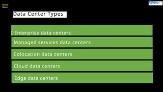
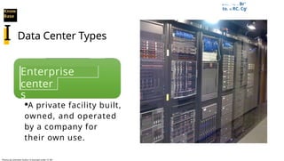
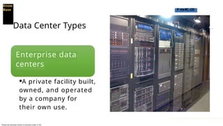
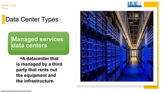
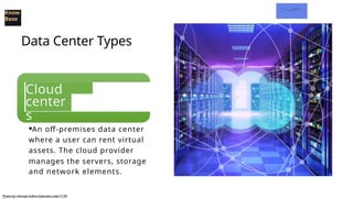
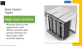
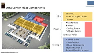
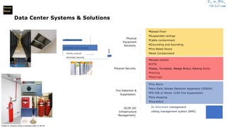
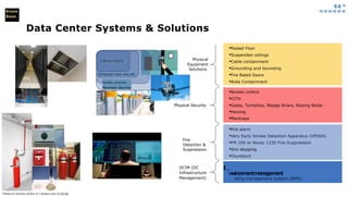
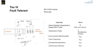
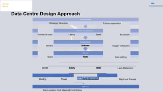
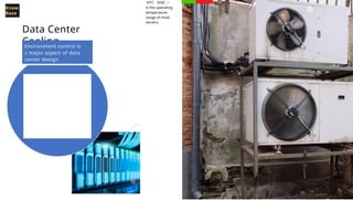
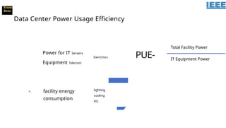
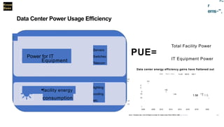
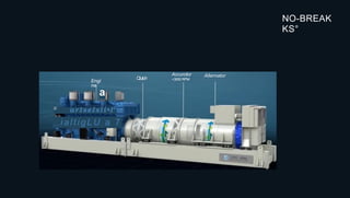
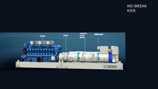
·Types of Data Centers
·Data Center Main Components
·Data Center systems and solutions
·Data Center Standards
·Data Center Tier Levels
·Interesting Aspects of DC Design
Know
Base
tMa
v Ma"
-1.(mIt"br
::
Know
Base
Data Center Types
[ Enterprise data centers
Managed services data centers
Colocation data centers
Cloud data centers
Edge data centers
El I I I o ..._ '-...aj
a . .—. Br'
to. n RC. CgI
Know
Base
Data Center Types
Enterprise
data
center
s
·A private facility built,
owned, and operated
by a company for
their own use.
I
Photos by Unknown Author Is licensed under CC BY-
Know
Base r rraRC..CD
Data Center Types
Enterprise data
centers
·A private facility built,
owned, and operated
by a company for
their own use.
Photos by Unknown Author Is licensed under CC BY-
U
A r m
r 1
Z
Iletxnerse American lJnivers ` •
Know 'edge
Base
Data Center Types
·A datacenter that
is managed by a third
party that rents out
the equipment and
the infrastructure.
Managed services
data centers
Photos by Unknown Author Is licensed under CC BY-SA
n-----
II......P=_= M
I
W
I
A
I
N
t
1Pli
ffi Pli
kLaintn-
J 1111111111 111111MM
I
killi!!!!!aWit_ritAck,
1 -
e•irgerallB—.
Know
Base
Data Center Types
Cloud
data
center
s
·An off-premises data center
where a user can rent virtual
assets. The cloud provider
manages the servers, storage
and network elements.
PhotosbyUnknownAuthorIslicensedunderCCBY-
....__-
---
a
"trn-
,;:e
LP--.Sg
irtRC..
.
7
.
e
.
,
.
Know
Base
Data Center
Types
I m m
·Placed close to the
application user.
Allows content and
service delivery to
local users with
minimal latency.
Photos by Unknown Author Is licensed under CC BY-SA
Edge data centers
Know
Base
Data Center Types
Edge data centers
·Placed close to the
application user.
Allows content and
service delivery to
local users with
minimal latency.
Photos by Unknown Author Is licensed under CC BY-SA
I
Data Center
Main
Components
t i c s ; I =
ra
Know
Base
Data Center Main Components
Photos by UnknownAuthor Is licensed under CC BY-SA
·Lc
'
rt: dal f▪ icl %Cr:
Know
Base
Data Center Main Components
·IT Racks.
·Fiber & Copper Cables
·Servers
IT
Photos by Unknown Author Is licensed under CC BY-SA
I Sr Br IC
ICI real
Know
Base
Data Center Main Components
·IT Racks.
·Fiber & Copper Cables
·Servers
·Transformers
·Gensets
·Fuelling System
·UPS & its Battery
is • Power Panels
·Chillers Plants.
·Pump System.
·DX Air Conditioning
·Humidification &
dehumidification system.
PhotosbyUnknownAuthorIslicensedunderCCBY-SA
IT
Power
Cooling -<
01, w_ffm_
ria Lc! fil
kM'
Know
Base
Data Center Systems & Solutions
CAbinel cons rols
Computer room controls

Facility controls
Perimeter Security
·Raised Floor
·Suspended ceilings
·Cable containment
·Grounding and bounding
·Fire Rated Doors
·Aisle Containment
·Access control
·CCTV
·Gates, Turnstiles, Wedge Briars, Raising Bollar
·Fencing
·Mantraps
·Fire alarm
·Very Early Smoke Detection Apparatus (VESDA)
·FM 200 or Novec 1230 Fire Suppression
·Sire stopping
·Oxyreduct
IA~Rronment management
uilding management system (BMS)
Photos by Unknown Author Is licensed under CC BY-SA
Physical
Equipment
Solutions
Physical Security
Fire Detection &
Suppression
DCIM (DC
Infrastructure
Management)
·r
gig.=
======
Know
Base
Data Center Systems & Solutions
Photos by Unknown Author Is I censed unter CC 8Y-SA
·Fire alarm
·Very Early Smoke Detection Apparatus (VESDA)
·FM 200 or Novec 1230 Fire Suppression
·Sire stopping
·Oxyreduct
I u
nvironmentmanagement
ilding management system (BMS)
·Raised Floor
·Suspended ceilings
·Cable containment
·Grounding and bounding
·Fire Rated Doors
·Aisle Containment
·Access control
·CCTV
·Gates, Turnstiles, Wedge Briars, Raising Bollar
·Fencing
·Mantraps
Physical
Equipment
Solutions
Physical Security
Fire
Detection &
Suppression
DCIM (DC
Infrastructure
Management)
Facility controls
Perimeter Security
Cabinet controls
Computer room writ roll
Data Centre
Standards
& Tier Levels
Data Centre
Standards
& Tier
Levels
IEEE
Bicsi
Jr
British Standards
atSTANDARDS
AL i..tr, 11(71
Photos by Unknown Author Is licensed under CC BY-SA
ANSI
American National
UptimeInstitute®
ADVANCING GLOBAL COMMUNICATIONS
ISO
Photos by Unknown Author Is licensed under CC BY-SA
UptimeInstitute°
Know
Base
T - w a -
- . . - . . . _ . 2 p i = 3
. 1 1 " -
• , . . , O m W a r s ( C 2 i
E t =
0%
20%
40%
100%
80%
60%
Unplanned Downtime
Avoidable
Outages
Other
5%
UPS System Failure
29%
I
Weather related
Water, Heat, Cooling
15%
Human Error
24%
III UPS System Failure
Weather related
·Other
G
0 Water, Heat, Cooling Failurenerator Failure0 IT Equip.
0 Human Error
Know
Base
:5c—
Ala'
r cc,
(Pr.
I
r-
'
i"1-)5
1
F15-161
I
• °
Tier Topology Categories
I
I
set
No fractional tiers all components
should comply
L_
Site Classification based on lowest
system rating.
4 tier levels or classes are defined
L_
·Fault tolerant
·99.995 availability
·Annual site related downtime ItOrth
·Concurrent Maintainable
·999.982 availability
·Annual site related downtime 1.611
·Redundant
·99.74996 availability
·Annual site related downtime 2211
311
°'
arn re .;
≥
Know
Base
Tier Topology Categories
Capacity
Components
Tier Classifications
represent broad
topology categories
based in the
redundancy in :
(diverse)
Distribution
Paths
now
ase
Tier Topology Categories
Tier 4
·Fault Tolerant
·99.995 availability
·Annual site related downtime
0.04h
·Concurrent Maintainable
·999.982 availability
·Annual site related downtime 1.6h
Redundant
99.74996 availability
Annual site related downtime 22h
Non-Redundant
99.671 availability
Annual site related downtime 28.8h
•
Tier 3 (
T1er 2
T1er
Know
Base
Tier 1
Basic
Capacity
-
01r afF
E ?
0
n
h a
r.
=
„ a
•
s
t h
·N = 2 UPS modules
·Single path
Function Tier I
Active Capacity Components to Support the IT
Load
Distribution Paths 1
Concurrently Maintainable No
Fault Tolerance No
Compartmentalization No
Continuous Cooling No
I VI
OAT/ CINTIM CAIMNIT
Know
Base
Tier 1
Basic Capacity
·N = 2 UPS modules
·Single path
Function Tier I
Active Capacity Components to Support the IT
Load
Distribution Paths 1
Concurrently Maintainable No
Fault Tolerance No
Compartmentalization No
Continuous Cooling No
UTILITY 0
1
1
1
ER
A
T
O
R
esszras
rel 1
L..
L_JL JL.J
S
k r '
OATH CONTIR CASINIIT
Know
Base
Tier II
Redundant
Components
grii LC VI
E.
·N = 2 UPS modules
·Single path.
·Adds redundant UPS module
Function TierII
Active Capacity Components to Support the IT N+1
Load
Distribution Paths 1
Concurrently Maintainable No
Fault Tolerance No
Compartmentalization No
Continuous Cooling No
4 4
a
•
3 UPS=N+1
wisp/maw e
Bus•A ..9
-
1
·Jim
.JL_J
DATA CENTER CABINET
Know
Base
Tier IV
Fault Tolerant
NEr-
t n VIC fr
Z
l o s s a a 1 D
·N=3 UPS modules
·Dual path
u
n
(i
GullRATOlta GVIIIRA UTIUTY
AU
A
T
S-
0
AT I - A
Nfl-A
3 UPS=N
.
., f_P
FUNCTION
Active Capacity Components to
Support the IT Load
Distribution Paths
Concurrently Maintainable
Fault Tolerance
Compartmentalization
Continuous Cooling
TIER IV
N
After any Failure
2
Simultaneous
ly Active
Yes
Yes
Yes
Yes
2 active
distribution
Paths
,s1lidN ..—' ........ ; g E
r . 11Pbr we,
. trl
r.
'---
1 F---
•r.:7
1
i_...._i
.:1....i..Lic:. C..1.
1
Lji_..R...iL..iL. _L. I
/
·Z
F
a
1.
7
Interesting
Aspects of
DC design
Know
Base
Data Cent
Know
Base
Data Centre Design Approach
Software arid applications
Latency
IT requirements
Switches
Future expansion
Bandwidth
Supper computers
Data cabling
Strategic Direction
Number of users
Servers
Space
Speed
Racks
Cooling
Safety BMS Leak Detection
Electrical Panels
DCIM
Power
nergy & Electromechanical
UPS Generator
4 r
Sae Civil
Site Location Civil Material Civil Works
10°C - 359C —
is the operating
temperature
range of most
servers.
Know
Base
Data Center
Cooling
Environment control is
a major aspect of data
center design
182C - 272C— is the
recommended inlet
temperature of IT
equipment by ASHRAE
(American Society of
Heating, Refrigerating,
and Air Conditioning
Engineers).
•
I
c
t
Data Centers
should be designed
to operate at an
optimum
temperature for
highest equipment
efficiency.
109C - 359C —
is the operating
temperature
range of most
servers.
I
text -
1/ c
Data Center
Cooling
Environment control is a
major aspect of data
center design
1.82C - 272C — is the
recommended inlet
temperature of IT
equipment by ASHRAE
(American Society of
Heating, Refrigerating,
and Air Conditioning
Engineers).
Know
Base
O
tdalIC1%Cr:
Know
Base
Cooling Technologies and Design
Chilled
Water
System
Free
Cooling
Direct
Expansion
(DX)
Evaporative
Cooling
Technology
Selection
Photos by Unknown Author Is licensed under CC BY-
Cooling
Design
Approach
Cold
Aisle/Hot
Aisle
Down
Flow /Up
Flow
In-row
Cooling
Direct-to-
Chip
Cooling
Cooling Technologies and Design
Know
Base
7C
o
l
dA
CRAC Ho[ Aisle
J
•
Photos by unknown Author N licensed under CC BY SA
a- a Mar-
&CI:eye,
Cooling
Design
Approach
Cold
Aisle/Hot
Aisle
Down
Flow /Up
Flow
In-row
Cooling
Direct-to-
Chip
Cooling
Cooling Technologies and Design
Know
Base
CRAC
LOOS< Seal &Witt
or prevsorre bdlance
111.
Photos by Unknown Author Is licensed under CC BY-SA
Know
Base
Pressure adjustment in-between
DC & surrounding area
PositivelyNegatively
Pressured RoomPressured Room
IMO
If Pressure
Switching Were
Used
411)Filtered air supply
• Clean
?
Dirty?
Dirty
Outlet air
..Bf
irta Ilca
Know
Base
Data Center Power design
ATS UPS
IT equipment
Utility Power
Generator
Cooling Building
System services
Know
Base
Data Center Power design
ATS
IT equipment
UPS
Utility Power
Generator
Cooling Building
System services
ca,
Know
Base
Back up Power Options
Battery Powered UPS Dynamic Rotary UPS (DRUPS)
Photos by Unknown Author Is licensed under CC BY-
Know
Base
Data Center Power Usage Efficiency
Power for IT Servers
Switches
Equipment Telecom
·I facility energy
consumption
lighting
cooling
etc.
PUE-
Total Facility Power
IT Equipment Power
pm
=
r
ems-",
Total Facility Power
PUE=
IT Equipment Power
Data center energy efficiency gains have flattened out
2.8
·/LAI: ·'4,1' 1• 'ii11.1 ·:u18 ·2019 ·25.?:
2.r 2.5
•
2
2
1.9.
2 Y.
1,8 1.65 1.67
1.58 • 1.5.
1,6 • •
1.4
1.2
1
2005 2038 2010 2012 2014 2016 2018 2020
Know
Base
Data Center Power Usage Efficiency
lcurrr. Yoreetrrl eat. rrrtir Ill fipert m p'rtad .Cl' metre nmer front 4‘00 to :WOUptlinelmtlide
r
Servers
Switches
Telecom
colPower for IT
Equipment
·facility energy
consumption
lighting
cooling
etc.
14 (I
edge
•
Thank You
Shaheer Shaaban, RCDD, PMP
Structured Cabling & IT
Infrastructure Expert
·Linkedln:
https://www.linkeoin.com/in/sha
heershaaban
·YouTube:
hups.ii www.youtube.com/c/Kno
wledgeBase2020
·Email:
Shaheersh@gmail.com
Know
Base Lebanese American University
NO-BREAK
KS°
a
Accurotor
<3000 RPM
Alternator
Clutch
G.
arIseIsli•IP
r s r i a l t i g L U a 7
Engi
ne
NO-BREAK
KS®
AMMO!
CON
RPM
Alternator
CONDITIONING MODE NO-BREAK KS®
Clean Conditioned Power
Input Voltage
03
01 Choke 02
1800 RPM at 60Hz (1500 RPM at 50Hz)
-II
UTILITY FAILURE NO-BREAK KS®
Input Voltage
0 I 0 I I I
0
3
Choke
Oz
INDEPENDENT MODE NO-BREAK KS®
MAINS
SUPPLY
COUPLIN
G CHOKE
TO mm*
DATACENTRE
DIESEL ENGINE
HITZINGER
Power Anytime. Anywhere.
ALTERNATOR KIN MODULE
MAINS OPERATION
During mains operation, the consumer load is supplied
from the mains via the choke.
T
r
=P
t 1-11
3
' 1
0 t . i t r i
s. sir*
P
4
0
.
la
'
m
i
i
,
f
t‘ 1 " . . s e a
rf
f
el
.
_4
1
.
1
,
4
p
Le -
i i i p t
. •
I
•
•
TO mme.
DATACENTRE
r e . o p r i m e a
Aiiaz
aim • •sump•-• mr-
low me-t -de •
MAINS OPERATION
The synchronous machine acts as a filter, and balances
stable voltage and reactive power between the mains and
the consumer.
COUPLIN
G
CHOKE
Astsa,__Lisi_ra
-
WartS4
P-
-
HITZI NG ER' 411 DIESEL ENGINE
Power. Anytime. Anywhere.
• •
ALTERNATOR KIN MODULE
MAINS
SUPPLY
•
•
MAINSPOWERFAILURE
When the mains supply fails, the KIN module keeps the load
supplied without interruptions. Simultaneously the diesel engine
is started.
TO mme.
DATACENTRE
MAINS COUPLING
SUPPLY CHOKE
e s t a i r •
•
•
%ars iiN1 PI 1,
Carl
" !S
w
F
'
le MCI.
·ia--im tr.
DIESEL ENGINE ALTERNATOR KIN MODULE
•
HITZINGER.
Power.Anytime.Anywhere.
DIESEL ENGINE
HITZINGER.
Power
. Anytime. Anywhere.
.4 lia_tati ass la.
961111P
111
.1
1F
I g
qi n i r
MAINSPOWERFAILURE
The electromagnetic clutch closes and the load is
transferred to the synchronous alternator. The diesel engine
and alternator supply the UPS load.
COUPLIN
G CHOKE
·•
4 W
e
1
/211r‘S 107
ALTERNATOR KIN MODULE
IL"
MAINS
SUPPLY
•
TO me-
DATACENTRE
A S .
•
MAINSPOWERRETURN
When the mains is back within tolerances for a certain
period, the consumer load is switched back to the mains.
The KIN module is re-charged.
MAINS COUPLING
SUPPLY CHOKE
TO -
DATACENTRE
1
1
1
1
51
Power.Anytime.Anywhere.
HITZINGER°
MAINS OPERATION
During mains operation, the consumer load is supplied from
the mains via the choke.
MAINS COUPLING TO mil.
SUPPLY CHOKE DATACENTRE
11
KIN MODULE
Original Static UPS plus Gen Set Layout
28 MW Tier 3 Design
120,000 ft2
Power System

Data Centre Basic Description and Types of Data Centre.pptx

  • 1.
    ·Types of DataCenters ·Data Center Main Components ·Data Center systems and solutions ·Data Center Standards ·Data Center Tier Levels ·Interesting Aspects of DC Design Know Base
  • 2.
    tMa v Ma" -1.(mIt"br :: Know Base Data CenterTypes [ Enterprise data centers Managed services data centers Colocation data centers Cloud data centers Edge data centers
  • 3.
    El I II o ..._ '-...aj a . .—. Br' to. n RC. CgI Know Base Data Center Types Enterprise data center s ·A private facility built, owned, and operated by a company for their own use. I Photos by Unknown Author Is licensed under CC BY-
  • 4.
    Know Base r rraRC..CD DataCenter Types Enterprise data centers ·A private facility built, owned, and operated by a company for their own use. Photos by Unknown Author Is licensed under CC BY-
  • 5.
    U A r m r1 Z Iletxnerse American lJnivers ` • Know 'edge Base Data Center Types ·A datacenter that is managed by a third party that rents out the equipment and the infrastructure. Managed services data centers Photos by Unknown Author Is licensed under CC BY-SA
  • 6.
    n----- II......P=_= M I W I A I N t 1Pli ffi Pli kLaintn- J1111111111 111111MM I killi!!!!!aWit_ritAck,
  • 7.
    1 - e•irgerallB—. Know Base Data CenterTypes Cloud data center s ·An off-premises data center where a user can rent virtual assets. The cloud provider manages the servers, storage and network elements. PhotosbyUnknownAuthorIslicensedunderCCBY-
  • 8.
    ....__- --- a "trn- ,;:e LP--.Sg irtRC.. . 7 . e . , . Know Base Data Center Types I mm ·Placed close to the application user. Allows content and service delivery to local users with minimal latency. Photos by Unknown Author Is licensed under CC BY-SA Edge data centers
  • 9.
    Know Base Data Center Types Edgedata centers ·Placed close to the application user. Allows content and service delivery to local users with minimal latency. Photos by Unknown Author Is licensed under CC BY-SA I
  • 10.
  • 11.
    t i cs ; I = ra Know Base Data Center Main Components Photos by UnknownAuthor Is licensed under CC BY-SA
  • 12.
    ·Lc ' rt: dal f▪icl %Cr: Know Base Data Center Main Components ·IT Racks. ·Fiber & Copper Cables ·Servers IT Photos by Unknown Author Is licensed under CC BY-SA
  • 13.
    I Sr BrIC ICI real Know Base Data Center Main Components ·IT Racks. ·Fiber & Copper Cables ·Servers ·Transformers ·Gensets ·Fuelling System ·UPS & its Battery is • Power Panels ·Chillers Plants. ·Pump System. ·DX Air Conditioning ·Humidification & dehumidification system. PhotosbyUnknownAuthorIslicensedunderCCBY-SA IT Power Cooling -<
  • 14.
    01, w_ffm_ ria Lc!fil kM' Know Base Data Center Systems & Solutions CAbinel cons rols Computer room controls Facility controls Perimeter Security ·Raised Floor ·Suspended ceilings ·Cable containment ·Grounding and bounding ·Fire Rated Doors ·Aisle Containment ·Access control ·CCTV ·Gates, Turnstiles, Wedge Briars, Raising Bollar ·Fencing ·Mantraps ·Fire alarm ·Very Early Smoke Detection Apparatus (VESDA) ·FM 200 or Novec 1230 Fire Suppression ·Sire stopping ·Oxyreduct IA~Rronment management uilding management system (BMS) Photos by Unknown Author Is licensed under CC BY-SA Physical Equipment Solutions Physical Security Fire Detection & Suppression DCIM (DC Infrastructure Management) ·r
  • 15.
    gig.= ====== Know Base Data Center Systems& Solutions Photos by Unknown Author Is I censed unter CC 8Y-SA ·Fire alarm ·Very Early Smoke Detection Apparatus (VESDA) ·FM 200 or Novec 1230 Fire Suppression ·Sire stopping ·Oxyreduct I u nvironmentmanagement ilding management system (BMS) ·Raised Floor ·Suspended ceilings ·Cable containment ·Grounding and bounding ·Fire Rated Doors ·Aisle Containment ·Access control ·CCTV ·Gates, Turnstiles, Wedge Briars, Raising Bollar ·Fencing ·Mantraps Physical Equipment Solutions Physical Security Fire Detection & Suppression DCIM (DC Infrastructure Management) Facility controls Perimeter Security Cabinet controls Computer room writ roll
  • 16.
  • 17.
  • 18.
    IEEE Bicsi Jr British Standards atSTANDARDS AL i..tr,11(71 Photos by Unknown Author Is licensed under CC BY-SA ANSI American National UptimeInstitute® ADVANCING GLOBAL COMMUNICATIONS ISO
  • 19.
    Photos by UnknownAuthor Is licensed under CC BY-SA UptimeInstitute°
  • 20.
    Know Base T - wa - - . . - . . . _ . 2 p i = 3 . 1 1 " - • , . . , O m W a r s ( C 2 i E t = 0% 20% 40% 100% 80% 60% Unplanned Downtime Avoidable Outages Other 5% UPS System Failure 29% I Weather related Water, Heat, Cooling 15% Human Error 24% III UPS System Failure Weather related ·Other G 0 Water, Heat, Cooling Failurenerator Failure0 IT Equip. 0 Human Error
  • 21.
    Know Base :5c— Ala' r cc, (Pr. I r- ' i"1-)5 1 F15-161 I • ° TierTopology Categories I I set No fractional tiers all components should comply L_ Site Classification based on lowest system rating. 4 tier levels or classes are defined L_ ·Fault tolerant ·99.995 availability ·Annual site related downtime ItOrth ·Concurrent Maintainable ·999.982 availability ·Annual site related downtime 1.611 ·Redundant ·99.74996 availability ·Annual site related downtime 2211
  • 22.
    311 °' arn re .; ≥ Know Base TierTopology Categories Capacity Components Tier Classifications represent broad topology categories based in the redundancy in : (diverse) Distribution Paths
  • 23.
    now ase Tier Topology Categories Tier4 ·Fault Tolerant ·99.995 availability ·Annual site related downtime 0.04h ·Concurrent Maintainable ·999.982 availability ·Annual site related downtime 1.6h Redundant 99.74996 availability Annual site related downtime 22h Non-Redundant 99.671 availability Annual site related downtime 28.8h • Tier 3 ( T1er 2 T1er
  • 24.
    Know Base Tier 1 Basic Capacity - 01r afF E? 0 n h a r. = „ a • s t h ·N = 2 UPS modules ·Single path Function Tier I Active Capacity Components to Support the IT Load Distribution Paths 1 Concurrently Maintainable No Fault Tolerance No Compartmentalization No Continuous Cooling No I VI OAT/ CINTIM CAIMNIT
  • 25.
    Know Base Tier 1 Basic Capacity ·N= 2 UPS modules ·Single path Function Tier I Active Capacity Components to Support the IT Load Distribution Paths 1 Concurrently Maintainable No Fault Tolerance No Compartmentalization No Continuous Cooling No UTILITY 0 1 1 1 ER A T O R esszras rel 1 L.. L_JL JL.J S k r ' OATH CONTIR CASINIIT
  • 26.
    Know Base Tier II Redundant Components grii LCVI E. ·N = 2 UPS modules ·Single path. ·Adds redundant UPS module Function TierII Active Capacity Components to Support the IT N+1 Load Distribution Paths 1 Concurrently Maintainable No Fault Tolerance No Compartmentalization No Continuous Cooling No 4 4 a • 3 UPS=N+1 wisp/maw e Bus•A ..9 - 1 ·Jim .JL_J DATA CENTER CABINET
  • 27.
    Know Base Tier IV Fault Tolerant NEr- tn VIC fr Z l o s s a a 1 D ·N=3 UPS modules ·Dual path u n (i GullRATOlta GVIIIRA UTIUTY AU A T S- 0 AT I - A Nfl-A 3 UPS=N . ., f_P FUNCTION Active Capacity Components to Support the IT Load Distribution Paths Concurrently Maintainable Fault Tolerance Compartmentalization Continuous Cooling TIER IV N After any Failure 2 Simultaneous ly Active Yes Yes Yes Yes 2 active distribution Paths ,s1lidN ..—' ........ ; g E r . 11Pbr we, . trl r. '--- 1 F--- •r.:7 1 i_...._i .:1....i..Lic:. C..1. 1 Lji_..R...iL..iL. _L. I / ·Z F a 1. 7
  • 28.
  • 29.
  • 30.
    Know Base Data Centre DesignApproach Software arid applications Latency IT requirements Switches Future expansion Bandwidth Supper computers Data cabling Strategic Direction Number of users Servers Space Speed Racks Cooling Safety BMS Leak Detection Electrical Panels DCIM Power nergy & Electromechanical UPS Generator 4 r Sae Civil Site Location Civil Material Civil Works
  • 31.
    10°C - 359C— is the operating temperature range of most servers. Know Base Data Center Cooling Environment control is a major aspect of data center design 182C - 272C— is the recommended inlet temperature of IT equipment by ASHRAE (American Society of Heating, Refrigerating, and Air Conditioning Engineers).
  • 32.
    • I c t Data Centers should bedesigned to operate at an optimum temperature for highest equipment efficiency. 109C - 359C — is the operating temperature range of most servers. I text - 1/ c Data Center Cooling Environment control is a major aspect of data center design 1.82C - 272C — is the recommended inlet temperature of IT equipment by ASHRAE (American Society of Heating, Refrigerating, and Air Conditioning Engineers). Know Base O
  • 33.
    tdalIC1%Cr: Know Base Cooling Technologies andDesign Chilled Water System Free Cooling Direct Expansion (DX) Evaporative Cooling Technology Selection Photos by Unknown Author Is licensed under CC BY-
  • 34.
    Cooling Design Approach Cold Aisle/Hot Aisle Down Flow /Up Flow In-row Cooling Direct-to- Chip Cooling Cooling Technologiesand Design Know Base 7C o l dA CRAC Ho[ Aisle J • Photos by unknown Author N licensed under CC BY SA
  • 35.
    a- a Mar- &CI:eye, Cooling Design Approach Cold Aisle/Hot Aisle Down Flow/Up Flow In-row Cooling Direct-to- Chip Cooling Cooling Technologies and Design Know Base CRAC LOOS< Seal &Witt or prevsorre bdlance 111. Photos by Unknown Author Is licensed under CC BY-SA
  • 36.
    Know Base Pressure adjustment in-between DC& surrounding area PositivelyNegatively Pressured RoomPressured Room IMO If Pressure Switching Were Used 411)Filtered air supply • Clean ? Dirty? Dirty Outlet air
  • 37.
    ..Bf irta Ilca Know Base Data CenterPower design ATS UPS IT equipment Utility Power Generator Cooling Building System services
  • 38.
    Know Base Data Center Powerdesign ATS IT equipment UPS Utility Power Generator Cooling Building System services
  • 39.
    ca, Know Base Back up PowerOptions Battery Powered UPS Dynamic Rotary UPS (DRUPS) Photos by Unknown Author Is licensed under CC BY-
  • 40.
    Know Base Data Center PowerUsage Efficiency Power for IT Servers Switches Equipment Telecom ·I facility energy consumption lighting cooling etc. PUE- Total Facility Power IT Equipment Power
  • 41.
    pm = r ems-", Total Facility Power PUE= ITEquipment Power Data center energy efficiency gains have flattened out 2.8 ·/LAI: ·'4,1' 1• 'ii11.1 ·:u18 ·2019 ·25.?: 2.r 2.5 • 2 2 1.9. 2 Y. 1,8 1.65 1.67 1.58 • 1.5. 1,6 • • 1.4 1.2 1 2005 2038 2010 2012 2014 2016 2018 2020 Know Base Data Center Power Usage Efficiency lcurrr. Yoreetrrl eat. rrrtir Ill fipert m p'rtad .Cl' metre nmer front 4‘00 to :WOUptlinelmtlide r Servers Switches Telecom colPower for IT Equipment ·facility energy consumption lighting cooling etc. 14 (I
  • 42.
    edge • Thank You Shaheer Shaaban,RCDD, PMP Structured Cabling & IT Infrastructure Expert ·Linkedln: https://www.linkeoin.com/in/sha heershaaban ·YouTube: hups.ii www.youtube.com/c/Kno wledgeBase2020 ·Email: Shaheersh@gmail.com Know Base Lebanese American University
  • 43.
  • 44.
  • 45.
    CONDITIONING MODE NO-BREAKKS® Clean Conditioned Power Input Voltage 03 01 Choke 02 1800 RPM at 60Hz (1500 RPM at 50Hz) -II
  • 46.
    UTILITY FAILURE NO-BREAKKS® Input Voltage 0 I 0 I I I 0 3 Choke Oz
  • 47.
  • 49.
    MAINS SUPPLY COUPLIN G CHOKE TO mm* DATACENTRE DIESELENGINE HITZINGER Power Anytime. Anywhere. ALTERNATOR KIN MODULE MAINS OPERATION During mains operation, the consumer load is supplied from the mains via the choke. T r =P t 1-11 3 ' 1 0 t . i t r i s. sir* P 4 0 . la ' m i i , f t‘ 1 " . . s e a rf f el . _4 1 . 1 , 4 p Le - i i i p t . • I • •
  • 50.
    TO mme. DATACENTRE r e. o p r i m e a Aiiaz aim • •sump•-• mr- low me-t -de • MAINS OPERATION The synchronous machine acts as a filter, and balances stable voltage and reactive power between the mains and the consumer. COUPLIN G CHOKE Astsa,__Lisi_ra - WartS4 P- - HITZI NG ER' 411 DIESEL ENGINE Power. Anytime. Anywhere. • • ALTERNATOR KIN MODULE MAINS SUPPLY • •
  • 51.
    MAINSPOWERFAILURE When the mainssupply fails, the KIN module keeps the load supplied without interruptions. Simultaneously the diesel engine is started. TO mme. DATACENTRE MAINS COUPLING SUPPLY CHOKE e s t a i r • • • %ars iiN1 PI 1, Carl " !S w F ' le MCI. ·ia--im tr. DIESEL ENGINE ALTERNATOR KIN MODULE • HITZINGER. Power.Anytime.Anywhere.
  • 52.
    DIESEL ENGINE HITZINGER. Power . Anytime.Anywhere. .4 lia_tati ass la. 961111P 111 .1 1F I g qi n i r MAINSPOWERFAILURE The electromagnetic clutch closes and the load is transferred to the synchronous alternator. The diesel engine and alternator supply the UPS load. COUPLIN G CHOKE ·• 4 W e 1 /211r‘S 107 ALTERNATOR KIN MODULE IL" MAINS SUPPLY • TO me- DATACENTRE A S . •
  • 53.
    MAINSPOWERRETURN When the mainsis back within tolerances for a certain period, the consumer load is switched back to the mains. The KIN module is re-charged. MAINS COUPLING SUPPLY CHOKE TO - DATACENTRE 1 1 1 1 51 Power.Anytime.Anywhere. HITZINGER°
  • 54.
    MAINS OPERATION During mainsoperation, the consumer load is supplied from the mains via the choke. MAINS COUPLING TO mil. SUPPLY CHOKE DATACENTRE 11 KIN MODULE
  • 55.
    Original Static UPSplus Gen Set Layout 28 MW Tier 3 Design 120,000 ft2 Power System