Download to read offline
![Nisarg M. Trivedi et al Int. Journal of Engineering Research and Applications www.ijera.com
ISSN : 2248-9622, Vol. 4, Issue 4( Version 7), April 2014, pp.17-23
www.ijera.com 17 | P a g e
Improvement of Surface Finish by Vibration Control in Machine
Tool Using Composite Material
Nisarg M. Trivedi*, Prof. J. R. Mevada**
*Student, M.Tech, (Department of mechanical engineering, ganpat university, kherva-384012),
**Associate prof., (Department of mechanical engineering, ganpat university, kherva-384012)
Abstract
In milling machine the main problem is vibration in machine tool which affects on quality of machined part.
Hence these vibrations needed to suppressed during machining. Aim of study is to control different parameters
like thickness of composite plates, cutting speed and depth of cut which affects on response like amplitude
(acceleration) of vibration and surface roughness of machined part. In present work machine tool vibration on
slotted table horizontal milling machine have been reduced using composites. In this work glass fiber epoxy
plates and glass fiber polyester plates are used as composites. Initially holes are drilled on each composite plate.
Mild steel plate is placed on the composite plates and setup is fixed to the table of horizontal milling machine
using nuts and bolts. A milling operation is carried out. Amplitude (acceleration) of vibration is recorded on the
screen of vibxpert signal analyzer and Surface roughness of machined mild steel plate is measured by tr110
surface roughness tester machine.
Keywords- horizontal milling machine, composite materials (glass fiber epoxy and glass fiber polyester
plates), vibxpert signal analyzer, tr110 surface roughness tester machine.
I. Introduction
Milling is the most common form of
machining, a material removal process, which can
create variety of features on part by cutting away the
material. In horizontal milling machine tool vibration
occurs during machining process because of in
homogeneous work piece material, disturbance in
work piece or tool and variation of chip cross section.
Effects of these vibration include reduction in tool
life, improper surface finish and unwanted noise in
machine tool. In order to suppressed these vibration,
composite materials have been used. In present work
glass fiber epoxy plates and glass fiber polyester
plates used as composite material. Fiber glass also
called glass reinforced plastic (GRP) or FRP is a fiber
reinforced polymer made of plastic matrix reinforced
by fine fibers of glass. Epoxy is thermosetting
polymer formed from reaction of an epoxide with
polyamine. Epoxies are known for their excellent
adhesion and excellent mechanical property.
Polyester is category of polymers which contain ester
functional group of main chain. Depending on
chemical structure polyester is can be thermoplastic.
In this study composites have been utilized as bed to
work piece because of its excellent damping
characteristics and also it act as vibration absorber.
Sung-kyum cho, Hyun-jun kim, Seung-hwan chang
[1] shows application of polymer composites to the
table top machine tool components for higher
stiffness and reduced weight. To determine the
specification of composite material vibration test
were carried out.. Amir Rashid, cornel mihai
nicolescu [2] work carried out for Active vibration
control in palletized work holding system for milling.
Palletized work holding system, due to their compact
design, offer an opportunity to design active control
system that are economical and easier to implement
in the case of milling machine. Xinhua long , hao
jiang, guang meng [3] presented active vibration
control for peripheral milling processes. In this
system work piece is driven by specially designed
active stage to control relative vibration between the
tool and work piece during milling process. Paper
presented by C.Andesson, M.Andersson, J.E.stahl [4]
shows experimental studies of cutting force variation
in face milling. Paper presented by Yang shaohong,
Wang anwen, Hu mingyong [5] shows damping
properties of viscoelastic laminated plates with an
unconstrained fiber reinforced layer. Using fiber
reinforced viscoelastic layer has little affect on the
nondimensional frequency, but can affectively
improve the damping characteristics and reduce the
resonance amplitude. Jean-Marie Berthelot,
Mustapha assarar, Youssef sefrani, Abderrahim EI
Mahi [6] work carried out for damping analysis of
composite materials and structures. This paper is
develop synthesis of damping analysis of laminated
materials, laminated with interleaved viscoelastic and
sandwich material. Paper presented by D.I.Kim,
S.C.Jung, J.E.Lee, S.H.Chang [7] shows parametric
study on design of composite foam resign concrete
sandwich structure for precision machine tool
RESEARCH ARTICLE OPEN ACCESS](https://image.slidesharecdn.com/d44081723-140526234157-phpapp01/85/D44081723-1-320.jpg)
![Nisarg M. Trivedi et al Int. Journal of Engineering Research and Applications www.ijera.com
ISSN : 2248-9622, Vol. 4, Issue 4( Version 7), April 2014, pp.17-23
www.ijera.com 18 | P a g e
structures. Ding Jiangmin [8] presented composite
concrete bed for CNC machine tool. Paper shows two
important functional requirement of CNC machine
tool bed are high structural stiffness and high
damping. Dr. Muhannad Z. khelifa, Hayder Moasa
Al-shukri [9] presented fatigue study on E –glass
fiber reinforced polyester composite under fully
reversed loading and spectrum loading. Result of
fatigue test show that the uniaxial composite has the
highest strength and fatigue degradation is also
highest. Paper presented by J.P.Talbot and
J.Woodhouse [10] work carried out for the vibration
damping of laminated plates. Paper presented by
C.Y.Huang , J- J Junz wang [11] shows effect of
cutting conditions on dynamic cutting factor and
process damping in milling.
II. Experimental work
Purpose of experimental work was to
reducing vibration during machining process. Glass
fiber epoxy and glass fiber polyester plates used as
composite material during experiment. Milling
experiment were conducted on the mild steel work
specimen mounted on two different type of
composite materials during machining process. The
experimental work was performed for work specimen
of mild steel and composite plates is
150mm×150mm×6mm.
Figure1. mild steel plate placed on composite plate
bolted to slotted table of milling machine
Glass fiber epoxy and glass fiber polyester plates
below mild steel plate is tightly bolted on table of
milling machine. Accelerometer is placed on mild
steel during machining operation. The response
signal amplitude (acceleration) is recorded and stored
in vibxpert signal analyzer. Then thickness of
composite plate is increased and observation are
recorded. Experiment are conducted for 6mm, 12mm
and 18 mm thickness of composite plates
respectively. After machining of MS plate the surface
roughness was measured by tr110 surface roughness
tester machine. For the experiment, total three
parameters are selected. These machining parameter
and their levels are shown in table 1.
Table 1. machining parameter and their level
Level Cutting
speed
(in rpm)
Thickness of
composite
plate
(in mm)
Depth of
cut
(in mm)
1 50 6 0.1
2 85 12 0.2
3 150 18 0.3
III. Result and Discussion
Minitab generated design is used with three
levels of each three factors. The number of
experiment was 27 each set of composite material
(glass fiber epoxy and glass fiber polyester).
Parameters like thickness of composite plate, cutting
speed and depth of cut affects on response parameter
like amplitude (acceleration) and surface roughness
shown in below table.
Table 2: Experimental result for glass fiber epoxy and glass fiber polyester composite plates
Glass fiber epoxy Glass fiber polyester
Run
order
Pt
type
Blocks Speed
(in
RPM)
Thickness
(in mm)
Depth
of cut
(in
mm)
Amplitude
(Acceleration)
in m/s2
Surface
roughness
(Ra)
in µm
Amplitude
(Acceleration)
in m/s2
Surface
roughness
(Ra)
in µm
1 1 1 50 18 0.3 0.259 1.58 0.269 2.19
2 1 1 50 12 0.1 0.240 1.86 0.319 2.16
3 1 1 150 18 0.3 0.298 2.01 0.662 2.41
4 1 1 50 12 0.3 0.236 2.43 0.170 2.64
5 1 1 150 18 0.1 0.834 1.34 0.499 2.04
6 1 1 50 6 0.2 0.231 2.53 0.427 2.68
7 1 1 50 6 0.3 0.231 2.28 0.335 2.34
8 1 1 85 12 0.3 0.214 2.72 0.319 2.38
9 1 1 150 18 0.2 0.621 1.62 0.670 2.28
10 1 1 150 6 0.3 1.567 2.67 1.194 2.72](https://image.slidesharecdn.com/d44081723-140526234157-phpapp01/85/D44081723-2-320.jpg)

![Nisarg M. Trivedi et al Int. Journal of Engineering Research and Applications www.ijera.com
ISSN : 2248-9622, Vol. 4, Issue 4( Version 7), April 2014, pp.17-23
www.ijera.com 22 | P a g e
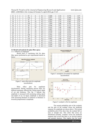
Figure 13. residual vs fits for surface roughness
Normal probability plot of the residuals and
the plot of residuals versus the predicted response for
surface roughness are shown. A check on probability
plot of the show that, the residual fall or near straight
line. This refers errors are distributed normally.
residuals versus the predicted response plot reveal
that there is no obvious pattern and unusual structure.
This implies that the model proposed is adequate.
Table 6 P-value is less than 0.05 which means that
the model is significant at 95% confident level.
Table 6.analysis of variance for surface roughness
Sourc
e
DF Seq
ss
Adj
ss
Adj
MS
F P
Cuttin
g
speed
2 0.053
42
0.053
42
0.02
671
0.96 0.40
1
Thick
ness
2 0.197
09
0.197
09
0.09
854
3.53 0.04
9
Depth
of cut
2 0.740
56
0.740
56
0.37
028
13.2
7
0.00
0
Error 20 0.557
93
0.557
93
0.02
790
Total 26 1.549
00
3.3 Discussion
Amplitude (acceleration) is increased with
increasing speed that indicates tool and work
piece is rigidly supported to each other. If work
piece is unsecured means not securely clamped
on table then friction of milling may cause it to
shift and alter the desired cuts.
Amplitude (acceleration) is increased with
increasing depth of cut that depends on tool life.
As tool is used then teeth will wear down and
become dull. A dull cutter is less capable of
making precision cuts.
Amplitude (acceleration) is decreased with
increasing thickness. With increasing thickness
of material vibration effect is reduced. If
vibration is unbalanced then there are several
factors affected like manual feed, improper
bolted joint during experiment.
Roughness is increased with speed then
decreased. Decreasing of surface roughness
define better surface finish. If tool wear
produced during increasing of cutting speed then
surface finish is improper.
Roughness is increased with increasing depth of
cut that depend on work piece quality. If work
piece quality is poor that defines poor surface
finishing.
Roughness decreasing with increasing thickness
which define better surface finish. If machine
tool should not sufficiently strong then it
increase the deflection during cutting which
affect on surface finishing.
IV. Conclusion
This experimental work improve the surface
quality of work piece by reducing vibration of
horizontal milling machine tool using two different
composite materials glass fiber epoxy and glass fiber
polyester.
In present work, two different types of composite
materials glass fiber epoxy and glass fiber
polyester used below the work piece. composite
materials reduces the vibrations of the system
during experimental observation. With increase
in thickness of composites the vibrations are
decreased.
During experiment out of the two materials,
amplitudes obtained are less for Glass fiber
epoxy material. Therefore, it can be concluded
that Glass fiber epoxy material can be used for
machine tool structures to reduce the effects of
vibrations.
The decrease of vibration amplitude has been
observed with increase of thickness between
table and work piece for glass fiber epoxy but for
glass fiber polyester vibration increases during
experiment.
Main effect plot and normal probability plot of
amplitude and surface roughness shows that
variation of response parameter with respect to
controllable parameter which define glass fiber
epoxy has better accuracy than glass fiber
polyester.
So it can be conclude that glass fiber epoxy is
more useful than glass fiber polyester to reduce
vibration effect.
References
[1] Sung-kyum cho, Hyun-jun kim, Seung-hwan
chang, The application of polymer
composites to the table top machine tool
components for higher stiffness and reduced](https://image.slidesharecdn.com/d44081723-140526234157-phpapp01/85/D44081723-6-320.jpg)
![Nisarg M. Trivedi et al Int. Journal of Engineering Research and Applications www.ijera.com
ISSN : 2248-9622, Vol. 4, Issue 4( Version 7), April 2014, pp.17-23
www.ijera.com 23 | P a g e
weight, composite structure 93 (2011) 492-
501.
[2] Amir Rashid, cornel Mihai Nicolescu,
Active vibration control in palletized work
holding system for milling , International
Journal of Machine Tools & Manufacture
46 (2006) 1626–1636.
[3] Xinhua Long, Hao Jiang, Guang Meng,
Active vibration control for peripheral
milling processes, Journal of Materials
Processing Technology 213 (2013) 660–
670.
[4] C.Andesson, M.Andersson, J.E.stahl,
experimental studies of cutting force
variation in face milling, International
journal of machine tool and manufacture 51
(2011) 67-76.
[5] Yang shaohong, Wang anwen, Hu
mingyong, damping properties of
viscoelastic laminated plates with an
unconstrained fiber reinforced layer, 2011
Third International Conference on
Measuring Technology and Mechatronics
Automation.
[6] Jean-Marie Berthelot, Mustapha assarar,
Youssef sefrani, Abderrahim EI Mahi,
damping analysis of composite materials
and structures, composite structures 85
(2008) 189-204.
[7] D.I.Kim, S.C.Jung, J.E.Lee, S.H.Chang,
parametric study on design of composite
foam resign concrete sandwich structure for
precision machine tool structures,
Composite Structures 75 (2006) 408–414.
[8] Ding Jiangmin, composite concrete bed for
CNC machine tool, 2010 International
Conference on Measuring Technology and
Mechatronics Automation.
[9] Dr. Muhannad Z. Khelifa, Hayder Moasa
Al-Shukri, fatigue study on E –glass fiber
reinforced polyester composite under fully
reversed loading and spectrum loading,
Eng.& Technology, Vol. 26, No.10, 2008.
[10] J.P.Talbot and J.Woodhouse, vibration
damping of laminated plates, Composites
Part A 28A (1997) 1007-1012.
[11] C.Y.Huang , J- J Junz wang, effect of
cutting conditions on dynamic cutting factor
and process damping in milling,
International journal of machine tool and
manufacturing 51 (2011) 320-330.](https://image.slidesharecdn.com/d44081723-140526234157-phpapp01/85/D44081723-7-320.jpg)

The study investigates the reduction of vibration during the milling process using composite materials, specifically glass fiber epoxy and polyester plates, to improve surface finish. Various parameters, including composite plate thickness, cutting speed, and depth of cut, are controlled to analyze their impact on vibration amplitude and surface roughness of the machined parts. Experimental results indicate significant variations in vibration response and surface quality, validating the use of composites for effective vibration suppression in machining applications.