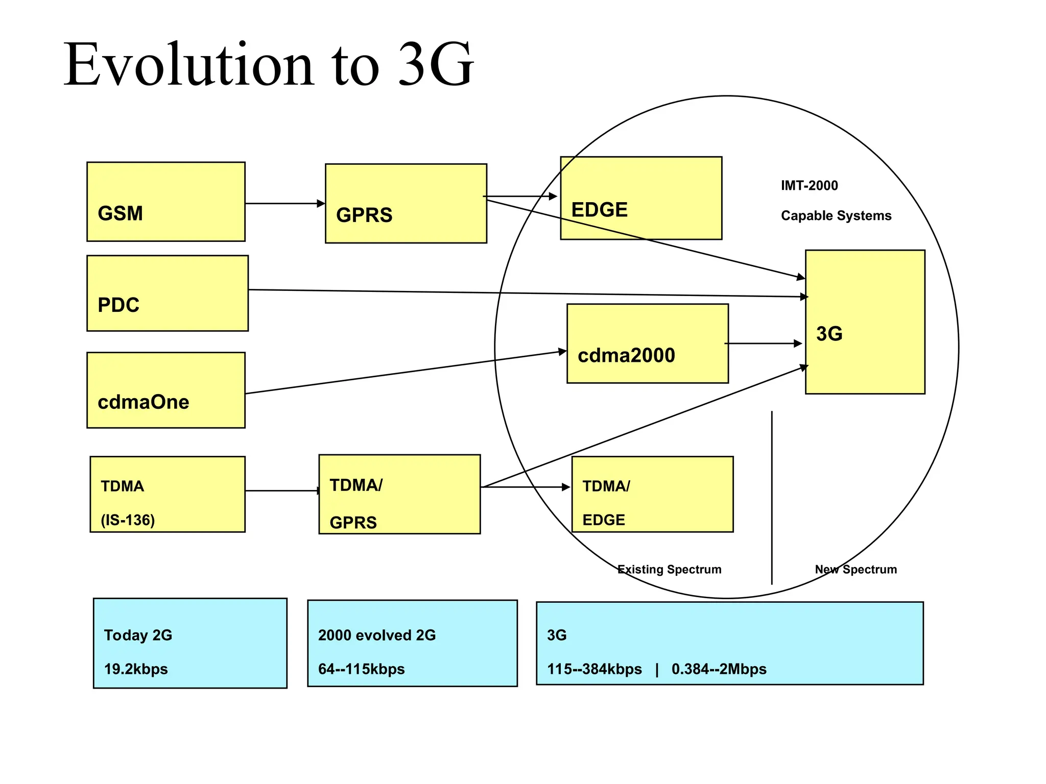
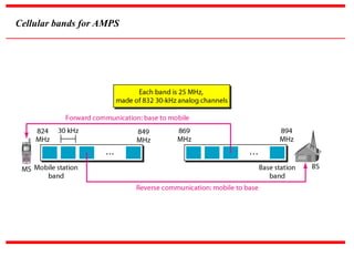
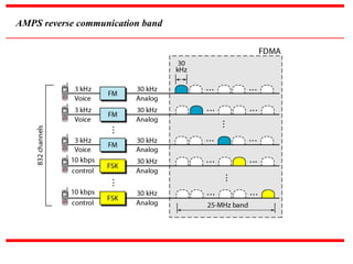
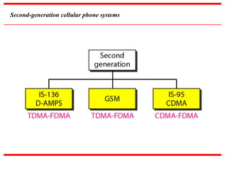
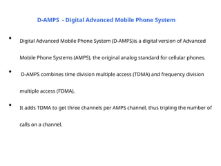
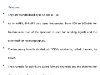
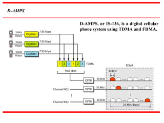
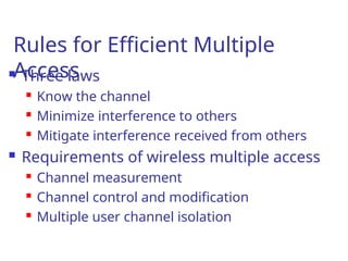
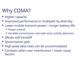
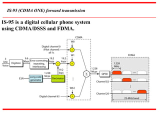
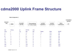
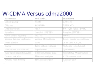
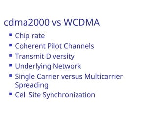
GSM
PDC
cdmaOne
TDMA
(IS-136)
GPRS EDGE
cdma2000
3G
Today 2G
19.2kbps
2000 evolved 2G
64--115kbps
3G
115--384kbps | 0.384--2Mbps
IMT-2000
Capable Systems
New Spectrum
Existing Spectrum
TDMA/
GPRS
TDMA/
EDGE
Evolution to 3G
AMPS is an analog cellular phone
system using FDMA.
Note
Cellular bands for AMPS
AMPS reverse communication band
Second-generation cellular phone systems
• Digital Advanced Mobile Phone System (D-AMPS)is a digital version of Advanced
Mobile Phone Systems (AMPS), the original analog standard for cellular phones.
• D-AMPS combines time division multiple access (TDMA) and frequency division
multiple access (FDMA).
• It adds TDMA to get three channels per AMPS channel, thus tripling the number of
calls on a channel.
D-AMPS - Digital Advanced Mobile Phone System
• They are standardised by IS-54 and IS-136.
• As in AMPS, D-AMPS also uses frequencies from 800 to 900MHz for
transmission. Half of the spectrum is used for sending signals and the
other half for receiving signals.
• The frequency band is divided into 30KHz sub-bands, called channels, by
FDMA.
• The channels for uplink are called forward channels and the channels for
Features:
D-AMPS
D-AMPS, or IS-136, is a digital cellular
phone system using TDMA and FDMA.
Rules for Efficient Multiple
Access
 Three laws
 Know the channel
 Minimize interference to others
 Mitigate interference received from others
 Requirements of wireless multiple access
 Channel measurement
 Channel control and modification
 Multiple user channel isolation
Why CDMA?
 Higher capacity
 Improved performance in multipath by diversity
 Lower mobile transmit power = longer battery life

Power control

Variable transmission rate with voice activity detection
 Allows soft handoff
 Sectorization gain
 High peak data rates can be accommodated
 Combats other-user interference = lower reuse
factors
IS-95 (CDMA ONE) forward transmission
IS-95 is a digital cellular phone system
using CDMA/DSSS and FDMA.
IS-95 (CDMA ONE) reverse transmission
cdma2000 Uplink Frame Structure
CRC
encoder
tail bits
Convolutional
or Turbo Coder
symbol
repetition
symbol
puncture
block
interleaver
modulation
symbol
C
channel
bits
Bits/
Frame
16
40
80
172
350
744
1512
3048
6120
CRC bits
6
6
8
12
16
16
16
16
16
tail
bits
8
8
8
8
8
8
8
8
8
Data Rate
kbps
1.5
2.7
4.8
9.6
19.2
38.4
76.8
153.6
307.2
Code
Rate
1/4
1/4
1/4
1/4
1/4
1/4
1/4
1/4
1/2
Repeats
16
8
4
2
1
1
1
1
1
Delete
1 of 5
1 of 9
none
none
none
none
none
none
none
Symbols
1536
1536
1536
1536
1536
3072
6144
12288
12288
Radio Configuration 3
C.S.0002-A-1 Fig 2.1.3.1.1.1-8
cdma2000 Uplink Modulator
C
C
C
A
B


d

d

d

c

)
cos( t
c

)
sin( t
c

I
long,
c Q
long,
c
+
+
+
+

+
_
sum
sum
1
D
w
C
w
2
S
w
1
S
w
Primary
Traffic
Secondary
Traffic 1
Secondary
Traffic 2
Control
Pilot
pulse
shape
pulse
shape
cdma2000 Downlink Frame Structure
Other similar tables in specification.
Bits/
Frame
21
55
125
267
552
1128
2280
4584
9192
20712
CRC bits
6
8
10
12
16
16
16
16
16
16
tail
bits
8
8
8
8
8
8
8
8
8
8
Data Rate
kbps
1.8
3.6
7.2
14.4
28.8
57.6
115.2
230.4
460.8
1036.8
Code
Rate
1/2
1/2
1/2
1/2
1/2
1/2
1/2
1/2
1/2
1/2
Repeats
8
4
2
1
1
1
1
1
1
1
Delete
none
none
none
none
none
none
none
none
none
2 of 18
Symbols
576
576
576
576
1152
2304
4608
9216
18432
36864
Radio Configuration 9
CRC
encoder
tail bits
Convolutional
or Turbo Coder
symbol
repetition
symbol
puncture
block
interleaver
modulation
symbol
channel
bits
W
cdma2000 1X DL Modulation
Processing
+
long
code
long
code
mask
0  1
1  -1
channel
gain
fwd pwr
ctrl gain
power
control
symbol
puncture
DEMUX
decimate
pwr ctrl
bit pos
I/Q scrambling
bit extract
power
control
bits
puncture
timing
800 Hz
W
YQ
YI
C.S.0002-A-1 Fig 3.1.3.1.1.1-18
modulation
symbol
rate
cdma2000 1X Downlink Modulation
I channel
pilot PN
Q channel
pilot PN
Walsh code
QOF code
I
Y
Q
Y





pulse
shape
pulse
shape
+
+
+
-
)
cos( t
c

)
sin( t
c

other
channels
other
channels
phase
rotate
for
QOF
Q
X
I
X
cdma2000 3X DL Modulation
Processing
+
long
code
long
code
mask
0  1
1  -1
channel
gain
fwd pwr
ctrl gain
power
control
symbol
puncture
DEMUX
decimate
pwr ctrl
bit pos
I/Q scrambling
bit extract
power
control
bits
puncture
timing
800 Hz
W
YQ1
YI1
modulation
symbol
rate
YQ2
YI2
YQ3
YI3
cdma2000 3X Downlink Modulation
same as below
same as above
output
carrier 1
output
carrier 2
output
carrier 3
YQ1
YI1
YQ2
YI2
YQ3
YI3
W-CDMA Versus cdma2000
Parameter W-CDMA cdma2000
Carrier spacing 5 MHz 3.75 MHz
Chip rate 4.096 MHz 3.6864 MHz
Data modulation BPSK FW – QPSK; RV - BPSK
Spreading Complex (OQPSK) Complex (OQPSK)
Power control frequency 1500 Hz 800 Hz
Variable data rate implement. Variable SF; multicode Repet., puncturing, multicode
Frame duration 10 ms 20 ms (also 5, 30, 40)
Coding Turbo and convolutional Turbo and convolutional
Base stations synchronized? Asynchronous Synchronous
Base station acquisition/detect 3 step; slot, frame, code Time shifted PN correlation
Forward link pilot TDM dedicated pilot CDM common pilot
Antenna beam forming TDM dedicated pilot Auxiliary pilot
cdma2000 vs WCDMA
 Chip rate
 Coherent Pilot Channels
 Transmit Diversity
 Underlying Network
 Single Carrier versus Multicarrier
Spreading
 Cell Site Synchronization

D-AMPS - Digital Advanced Mobile Phone System

  • 1.
    GSM PDC cdmaOne TDMA (IS-136) GPRS EDGE cdma2000 3G Today 2G 19.2kbps 2000evolved 2G 64--115kbps 3G 115--384kbps | 0.384--2Mbps IMT-2000 Capable Systems New Spectrum Existing Spectrum TDMA/ GPRS TDMA/ EDGE Evolution to 3G
  • 2.
    AMPS is ananalog cellular phone system using FDMA. Note
  • 3.
  • 4.
  • 5.
  • 6.
    • Digital AdvancedMobile Phone System (D-AMPS)is a digital version of Advanced Mobile Phone Systems (AMPS), the original analog standard for cellular phones. • D-AMPS combines time division multiple access (TDMA) and frequency division multiple access (FDMA). • It adds TDMA to get three channels per AMPS channel, thus tripling the number of calls on a channel. D-AMPS - Digital Advanced Mobile Phone System
  • 7.
    • They arestandardised by IS-54 and IS-136. • As in AMPS, D-AMPS also uses frequencies from 800 to 900MHz for transmission. Half of the spectrum is used for sending signals and the other half for receiving signals. • The frequency band is divided into 30KHz sub-bands, called channels, by FDMA. • The channels for uplink are called forward channels and the channels for Features:
  • 8.
    D-AMPS D-AMPS, or IS-136,is a digital cellular phone system using TDMA and FDMA.
  • 9.
    Rules for EfficientMultiple Access  Three laws  Know the channel  Minimize interference to others  Mitigate interference received from others  Requirements of wireless multiple access  Channel measurement  Channel control and modification  Multiple user channel isolation
  • 10.
    Why CDMA?  Highercapacity  Improved performance in multipath by diversity  Lower mobile transmit power = longer battery life  Power control  Variable transmission rate with voice activity detection  Allows soft handoff  Sectorization gain  High peak data rates can be accommodated  Combats other-user interference = lower reuse factors
  • 11.
    IS-95 (CDMA ONE)forward transmission IS-95 is a digital cellular phone system using CDMA/DSSS and FDMA.
  • 12.
    IS-95 (CDMA ONE)reverse transmission
  • 13.
    cdma2000 Uplink FrameStructure CRC encoder tail bits Convolutional or Turbo Coder symbol repetition symbol puncture block interleaver modulation symbol C channel bits Bits/ Frame 16 40 80 172 350 744 1512 3048 6120 CRC bits 6 6 8 12 16 16 16 16 16 tail bits 8 8 8 8 8 8 8 8 8 Data Rate kbps 1.5 2.7 4.8 9.6 19.2 38.4 76.8 153.6 307.2 Code Rate 1/4 1/4 1/4 1/4 1/4 1/4 1/4 1/4 1/2 Repeats 16 8 4 2 1 1 1 1 1 Delete 1 of 5 1 of 9 none none none none none none none Symbols 1536 1536 1536 1536 1536 3072 6144 12288 12288 Radio Configuration 3 C.S.0002-A-1 Fig 2.1.3.1.1.1-8
  • 14.
    cdma2000 Uplink Modulator C C C A B   d  d  d  c  ) cos(t c  ) sin( t c  I long, c Q long, c + + + +  + _ sum sum 1 D w C w 2 S w 1 S w Primary Traffic Secondary Traffic 1 Secondary Traffic 2 Control Pilot pulse shape pulse shape
  • 15.
    cdma2000 Downlink FrameStructure Other similar tables in specification. Bits/ Frame 21 55 125 267 552 1128 2280 4584 9192 20712 CRC bits 6 8 10 12 16 16 16 16 16 16 tail bits 8 8 8 8 8 8 8 8 8 8 Data Rate kbps 1.8 3.6 7.2 14.4 28.8 57.6 115.2 230.4 460.8 1036.8 Code Rate 1/2 1/2 1/2 1/2 1/2 1/2 1/2 1/2 1/2 1/2 Repeats 8 4 2 1 1 1 1 1 1 1 Delete none none none none none none none none none 2 of 18 Symbols 576 576 576 576 1152 2304 4608 9216 18432 36864 Radio Configuration 9 CRC encoder tail bits Convolutional or Turbo Coder symbol repetition symbol puncture block interleaver modulation symbol channel bits W
  • 16.
    cdma2000 1X DLModulation Processing + long code long code mask 0  1 1  -1 channel gain fwd pwr ctrl gain power control symbol puncture DEMUX decimate pwr ctrl bit pos I/Q scrambling bit extract power control bits puncture timing 800 Hz W YQ YI C.S.0002-A-1 Fig 3.1.3.1.1.1-18 modulation symbol rate
  • 17.
    cdma2000 1X DownlinkModulation I channel pilot PN Q channel pilot PN Walsh code QOF code I Y Q Y      pulse shape pulse shape + + + - ) cos( t c  ) sin( t c  other channels other channels phase rotate for QOF Q X I X
  • 18.
    cdma2000 3X DLModulation Processing + long code long code mask 0  1 1  -1 channel gain fwd pwr ctrl gain power control symbol puncture DEMUX decimate pwr ctrl bit pos I/Q scrambling bit extract power control bits puncture timing 800 Hz W YQ1 YI1 modulation symbol rate YQ2 YI2 YQ3 YI3
  • 19.
    cdma2000 3X DownlinkModulation same as below same as above output carrier 1 output carrier 2 output carrier 3 YQ1 YI1 YQ2 YI2 YQ3 YI3
  • 20.
    W-CDMA Versus cdma2000 ParameterW-CDMA cdma2000 Carrier spacing 5 MHz 3.75 MHz Chip rate 4.096 MHz 3.6864 MHz Data modulation BPSK FW – QPSK; RV - BPSK Spreading Complex (OQPSK) Complex (OQPSK) Power control frequency 1500 Hz 800 Hz Variable data rate implement. Variable SF; multicode Repet., puncturing, multicode Frame duration 10 ms 20 ms (also 5, 30, 40) Coding Turbo and convolutional Turbo and convolutional Base stations synchronized? Asynchronous Synchronous Base station acquisition/detect 3 step; slot, frame, code Time shifted PN correlation Forward link pilot TDM dedicated pilot CDM common pilot Antenna beam forming TDM dedicated pilot Auxiliary pilot
  • 21.
    cdma2000 vs WCDMA Chip rate  Coherent Pilot Channels  Transmit Diversity  Underlying Network  Single Carrier versus Multicarrier Spreading  Cell Site Synchronization