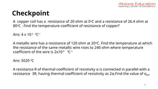
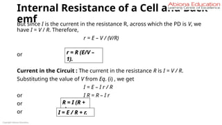
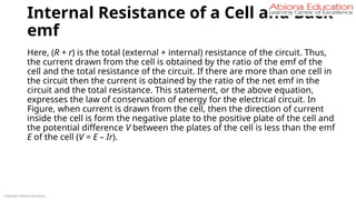
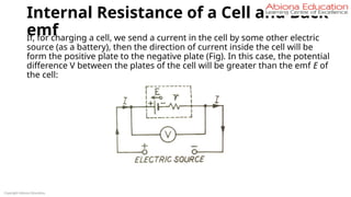
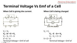
This PPT is for Current Electricity chapter. The PPT includes the theoretical concept and solved and unsolved questions in the form of checkpoints in between the chapter. This can be used for board level exams as well as for competitive exams for Engineering and medical.


![Copyright Abiona Education
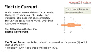
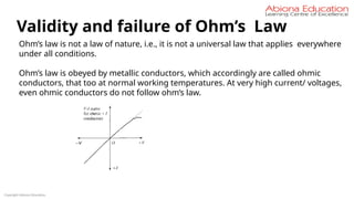
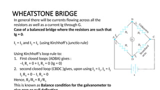
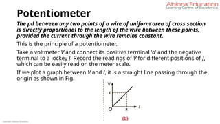
Conclusion
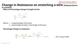
Resistance of the conductor depends on –
1. Length
2. area of cross-section
3. Nature of its material.
Precise measurements have shown that –
Resistance of a uniform metallic conductor is directly proportional to its length (l)
and inversely proportional to the area of cross-section (A). That is,
R l
∝ and R 1/A
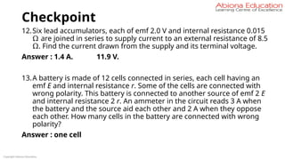
∝
Combining Eqs. we get , R l / A
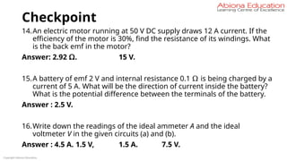
∝
or, R = ρ l / A
where ρ (rho) is a constant of proportionality and is called the electrical resistivity of
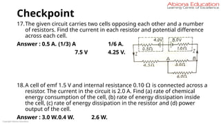
the material of the conductor.
SI unit of resistivity is Ω m. [ ρ = RA/l = Ω x m2
/ m = Ω x m ]
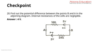
Factors On Which Resistance Of Conductor Depends](https://image.slidesharecdn.com/currentelectricity-250806140105-847f5fc0/85/Current-Electricity-for-JEE-preparation-pptx-34-320.jpg)


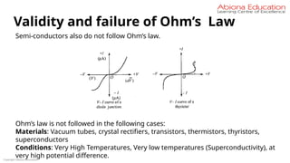


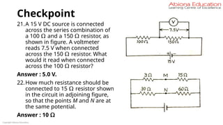
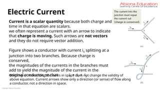
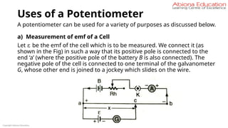
![Effect of Temperature on Resistivity &
Resistance
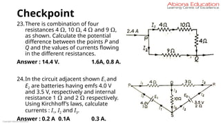
74
Temperature coefficient of Resistivity
RT = RTo [ 1 + α(T – To) + β (T – To)2
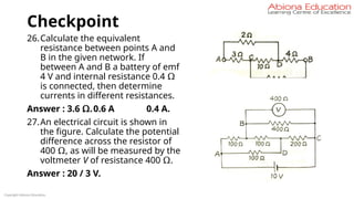
]
Here α, β are called temperature
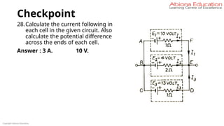
coefficient of resistivity.
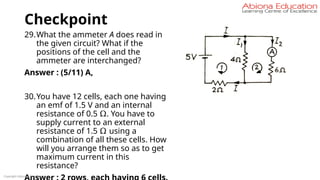
In case of pure metal, β is very small, so
the resistance varies linearly with the rise
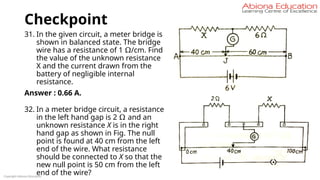
in temperature.
RT = RTo [ 1 + α(T – To)]
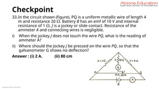
Similarly, resistivity also varies linearly with the rise in temperature -
ρT = ρTo [ 1 + α(T – To)]
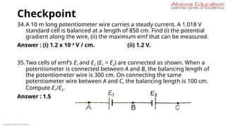
Dimension of α : (Temperature)- 1](https://image.slidesharecdn.com/currentelectricity-250806140105-847f5fc0/85/Current-Electricity-for-JEE-preparation-pptx-74-320.jpg)
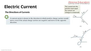
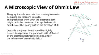
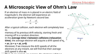
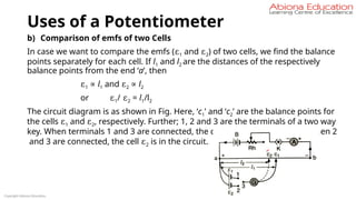
![Effect of Temperature on Resistivity &
Resistance
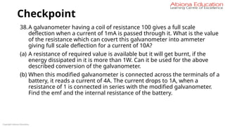
75
Temperature coefficient of Resistivity
RT = RTo [ 1 + α(T – To) + β (T – To)2
]
Here α, β are called temperature
coefficient of resistivity.
In case of pure metal, β is very small, so
the resistance varies linearly with the rise
in temperature.
RT = RTo [ 1 + α(T – To)]
Similarly, resistivity also varies linearly with the rise in temperature -
ρT = ρTo [ 1 + α(T – To)]
Dimension of α : (Temperature)- 1](https://image.slidesharecdn.com/currentelectricity-250806140105-847f5fc0/85/Current-Electricity-for-JEE-preparation-pptx-75-320.jpg)


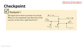
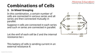
![Combinations of Cells
∴ Total resistance of the circuit = (r/n + R)
If the current in the external circuit be I, then I = E / [(r/n) + R] = n E / (r +
nR)
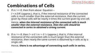
i) If r << R, that is, if the internal resistance of the cells is much smaller
than the external resistance, the r can be neglected in comparison to n
R. Then, from above equation –
I = n E / n R = E / R (approx.), that is, the total current will be equal to the current
given by a single cell. Hence, there is no advantage of connecting cells of small
internal resistance in parallel.
ii) If r >> R, that is, if the internal resistance of the cells is larger than the
external resistance, then the current will be I = n E/ r (approx.).
This current is nearly n times the current given by a single cell. Hence, when the
internal resistance of the cells is much larger than the external resistance, then
the cells should be connected in parallel.
Copyright Abiona Education](https://image.slidesharecdn.com/currentelectricity-250806140105-847f5fc0/85/Current-Electricity-for-JEE-preparation-pptx-116-320.jpg)
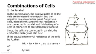
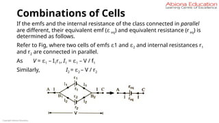
![Combinations of Cells
The total emf of n cells connected in one series is n E. Since, all the series
are connected in parallel, the emf of the battery as a whole will also be n
E. Similarly, the total internal resistance of cells in a series is n r. Such m
series are connected in parallel.
Hence, if the internal resistance of the whole battery be R1, then
1 / R1 = 1 / n r + 1 / n r + … up to m terms = m / nr
or R1 = nr / m.
∴ Total resistance of the circuit = (nr/m + R)
If the current in the external circuit be I, then –
I = n E / [(n r/m) + R] = m n E / (n r + m R).
Copyright Abiona Education](https://image.slidesharecdn.com/currentelectricity-250806140105-847f5fc0/85/Current-Electricity-for-JEE-preparation-pptx-118-320.jpg)
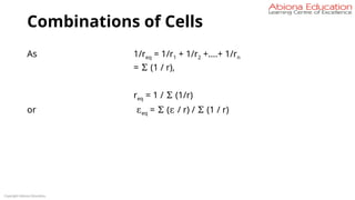
![Combinations of Cells
We have : I = n E / [(n r/m) + R] = m n E / (n r + m R)
It is clear from the above equation that for the value of I to be maximum,
the value of (n r + m R) should be minimum.
Now, n r + m R =
Therefore, for (n r + m R) to be minimum, the quantity
should be minimum . As this quantity is in square it cannot be negative,
hence its minimum value will be zero, that is,
or
Copyright Abiona Education](https://image.slidesharecdn.com/currentelectricity-250806140105-847f5fc0/85/Current-Electricity-for-JEE-preparation-pptx-119-320.jpg)
![Combinations of Cells
or n r = m R
or R = n r / m.
But n r / m is the internal resistance of the whole battery.
Thus, in mixed grouping the current in the external circuit will be maximum
when the internal resistance of the whole battery is equal to the external
resistance.
By substituting n r / m = R in equation I = n E / [(n r/m) + R] = m n E / (n r + m
R),
Copyright Abiona Education](https://image.slidesharecdn.com/currentelectricity-250806140105-847f5fc0/85/Current-Electricity-for-JEE-preparation-pptx-120-320.jpg)


![Uses of a Potentiometer
With the help of the jockey, we find the balance point ‘c’, when the
galvanometer shows no deflection. As the + ve pole of the cell is joined to
the point ‘a’ directly (i.e., without any resistance), the point ‘a’ and the + ve
pole of the cell are at the same potential. Since the galvanometer connected
between the –ve pole and the point ‘c’ shows no deflection, –ve pole of the
cell and the point ‘c’ are at the same potential. Clearly,
ε = pd between the +ve and –ve poles of the cell
= pd across ac
Let ac = x. From the graph [Fig], find the corresponding value of V which is
equal to ε (i.e., the emf of the cell).
Copyright Abiona Education](https://image.slidesharecdn.com/currentelectricity-250806140105-847f5fc0/85/Current-Electricity-for-JEE-preparation-pptx-145-320.jpg)

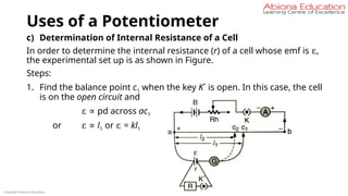
![Uses of a Potentiometer
2. Again find the balance point c2 when the key K´ is closed and a
resistance R is in the circuit. In this case the cell is in the closed circuit
and
V = pd across ac2
i.e., V ∝ I2 or V = kl2
We know that r = [(ε – V) / V] x R
⇒ r = [(kl1 – kl2 ) / k2 l2 ] x R
⇒ r = [(l1 – l2 )/ l2 ] x R
Copyright Abiona Education](https://image.slidesharecdn.com/currentelectricity-250806140105-847f5fc0/85/Current-Electricity-for-JEE-preparation-pptx-149-320.jpg)