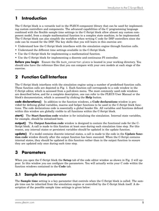
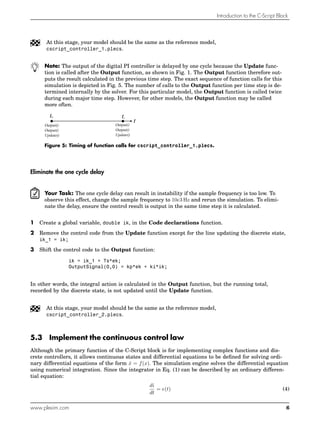
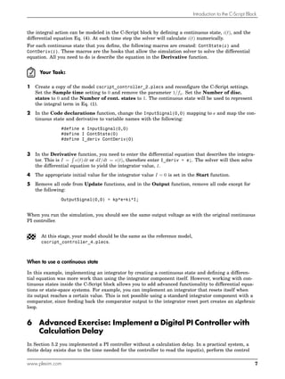
The document is a tutorial that introduces the C-Script block in PLECS, which allows implementing custom controllers and components using C code. It discusses how the C-Script block interfaces with the simulation engine via function calls, its parameters including sample time settings, and provides exercises to implement a mathematical function and digital PI controllers with and without calculation delays.
Introduction to Problem Solving and Algorithm Design
Using the above Code of Ethics, Pick at least 2 of the 8 principles and describe what these principles mean to you. In your write-up, summarize the principles you selected in your own words and provide at least one example of an activity or action you could take that would support each principle and one example of an activity or action that you believe would violate each principle. Be sure your document is well-written with minimal grammatical and spelling issues.
Cmis 102 Enthusiastic Study / snaptutorial.comStephenson22
Introduction to Problem Solving and Algorithm Design
Using the above Code of Ethics, Pick at least 2 of the 8 principles and describe what these principles mean to you. In your write-up, summarize the principles you selected in your own words and provide at least one example of an activity or action you could take that would support each principle and one example of an activity or action that you believe would violate each principle. Be sure your document is well-written with minimal grammatical and spelling issues.
Cmis 102 Effective Communication / snaptutorial.comHarrisGeorg12
CMIS 102 Homework 1 Solution
Introduction to Problem Solving and Algorithm Design
Using the above Code of Ethics, Pick at least 2 of the 8 principles and describe what these principles mean to you. In your write-up, summarize the principles you selected in your own words and provide at least one example of an activity or action you could take that would support each principle and one example of an activity or action that you believe would violate each principle. Be sure your document is well-written with minimal grammatical and spelling issues.
Cmis 102 Enthusiastic Study / snaptutorial.comStephenson22
Introduction to Problem Solving and Algorithm Design
Using the above Code of Ethics, Pick at least 2 of the 8 principles and describe what these principles mean to you. In your write-up, summarize the principles you selected in your own words and provide at least one example of an activity or action you could take that would support each principle and one example of an activity or action that you believe would violate each principle. Be sure your document is well-written with minimal grammatical and spelling issues.
Cmis 102 Effective Communication / snaptutorial.comHarrisGeorg12
CMIS 102 Homework 1 Solution
Introduction to Problem Solving and Algorithm Design
Using the above Code of Ethics, Pick at least 2 of the 8 principles and describe what these principles mean to you. In your write-up, summarize the principles you selected in your own words and provide at least one example of an activity or action you could take that would support each principle and one example of an activity or action that you believe would violate each principle. Be sure your document is well-written with minimal grammatical and spelling issues.
15LLP108_Demo4_LedBlinking.pdf1. Introduction In D.docxfelicidaddinwoodie
15LLP108_Demo4_LedBlinking.pdf
1. Introduction
In Demo3, we have learned how to read sensor values of light, temperature and humidity of a node
and output these values to the console. In this demonstration, we will use the code from Demo3 and
learn how to turn on/off the LEDs and make them blinking regularly on the sensor node XM1000,
meanwhile to count how many times the LED has blinked and output the count to the console.
2. Timer
In order to make the blue LED on the XM1000 sensor node to blink in every half second (i.e. On 0.5S
and Off 0.5S), we also need a timer. Follow the instructions in Demo3 for configure and reset a timer.
We aslo need to create an infinite while() loop so that it runs our functions repeatedly, such as
counting the times the LED has blinked, output the counter’s value and actually turn on or off the
LEDs to make it blinking.
Please follow timer and while() loop structure in Demo3.
3. LED Blinking
To get access to the LED functionalities in Contiki, we need to include the LED header file in the
source code:
#include "leds.h" // file is in directory /home/user/contiki/core/dev
After the process begin, we have to initialise the LEDs on the sensor node by calling the following
function:
leds_init(); // Initialise the LEDs
And finally we can turn on, off, or blink the LEDs by the following functions:
void leds_on(unsigned char leds);
void leds_off(unsigned char leds);
void leds_toggle(unsigned char leds);
void leds_invert(unsigned char leds);
For example, if you want to blink the Blue LED, yon need to call the toggle function as:
void leds_toggle(LEDS_BLUE); // Toggle the blue LED
4. Exercise
Modify the program from Demo3 with periodic timer to make the BLUE led blinking in every half
second, also to count the blinking times and output the counted number to the console.
Can your change the code so that the BLUE LED is lighted for 1 second and off for 0.5 second
periodically?
15LLP108 – Internet of Things and Applications
Lab Session 2: Demo 4 – LED Blinking
Prepared by Xiyu Shi
5. Source code
Here is the source code for reference
#include "contiki.h"
#include "leds.h"
#include <stdio.h> /* for printf() */
static struct etimer timer;
/*____________________________________________________*/
PROCESS(led_blinking_process, "LED Blinking Process");
PROCESS(LED_process, "LED process");
AUTOSTART_PROCESSES(&LED_process);
/*____________________________________________________*/
PROCESS_THREAD(LED_process, ev, data)
{
static int count = 0;
PROCESS_BEGIN();
etimer_set(&timer, CLOCK_CONF_SECOND/2); // 0.5S timer
leds_init(); // intialise the LEDs
while(1) {
PROCESS_WAIT_EVENT_UNTIL(ev==PROCESS_EVENT_TIMER); // wait for timer event
count++; // count the blinking times
process_start(&led_blinking_process, NULL); // to blink the BLUE Led
printf("Count: %d\n", count); // output the counte ...
PVS-Studio and Continuous Integration: TeamCity. Analysis of the Open RollerC...Andrey Karpov
One of the most relevant scenarios for using the PVS-Studio analyzer is its integration into CI systems. Even though a project analysis by PVS-Studio can already be embedded with just a few commands into almost any continuous integration system, we continue to make this process even more convenient. PVS-Studio now supports converting the analyzer output to the TeamCity format-TeamCity Inspections Type. Let's see how it works.
ELE2303 Assign 1 Page 1 ELE2303 Embedded Systems Design.docxjack60216
ELE2303 Assign 1 Page | 1
ELE2303 Embedded Systems Design
Assignment 1 – Gas Monitor Unit Stage 1
Description Marks out of Wtg (%) Due date
Gas Monitor Unit – Stage 1 200 20 28/04/14
Purpose
This assessment is intended to evaluate the student’s capability in selecting and configuring a
microcontroller unit (MCU), designing simple interface hardware and writing subroutines to
operate those interfaces.
Please note – the purpose of studying a ‘design’ course like this, is that you learn how to design
hardware and write programs to solve new problems. This requires you to understand the how
individual parts of the microcontroller function and how to control them with a program. You are
expected to link together pieces of interface circuitry and combine segments of program you
learn about in the course materials, into a structured solution. Do not expect to find a ‘solution’
to this problem on the internet. Expect that you have to create it!
Grading of this assessment
This task will be assessed against the course objectives 1, 2, 3, 4, 6 and 7. This assessment will
be graded (F, C, B, A, HD) using a rubric marking scheme against criteria such as: the
appropriate selection and use of microcomputer hardware; the design of I/O hardware to meet a
specification; implementation of software to meet a specification; quality of documentation
including organisation of ideas and format; spelling, grammar and punctuation. Note - this
course is a communications benchmark course, hence marks will be awarded for the quality of
documentation.
Assignment Requirements
This assessment requires students to meet the requirements the specification below. Select a
suitable microcontroller from the PIC18 family, design simple interface hardware, write
and test some C programs (subroutines) to operate the hardware interface and then document
the hardware and software as a proposed design. Software is to be written in C using the
MPLAB X IDE. You must create an MPLAB X project which may include one or more C
source files. The testing is to be completed using either: the Oshonsoft PIC18 simulator or the
MPLAB X simulator.
There is NO requirement to assemble any hardware, or layout a PCB for this assignment.
The circuit design for the hardware may be drawn using electronics CAD software, OR hand-
drawn and scanned, for inclusion in the documentation. The ‘hardware’ can be successfully
configured and simulated on the Oshonsoft PIC18 simulator or the MPLAB simulator. A few
screen captures of the software under-going testing are to be included in the documentation.
ELE2303 Assign 1 Page | 2
Each student is required to submit:
1. A report in PDF format which includes:
a brief introduction (100 – 150 words) outlining the design requirements based on the
specification.
the hardware design (250 – 300 words) explaining the key elements of the design and
how they meet the specification, plus ...
CyberLab Training Division :
Intel VTune Amplifier is a commercial application for software performance analysis for 32 and 64-bit x86 based machines, and has both GUI and command line interfaces. It is available for both Linux and Microsoft Windows operating systems. Although basic features work on both Intel and AMD hardware, advanced hardware-based sampling requires an Intel-manufactured CPU.
Whether you are tuning for the first time or doing advanced performance optimization, Intel® VTune Amplifier provides a rich set of performance insight into CPU & GPU performance, threading performance & scalability, bandwidth, caching and much more. Analysis is faster and easier because VTune Amplifier understands common threading models and presents information at a higher level that is easier to interpret. Use its powerful analysis to sort, filter and visualize results on the timeline and on your source.
It is available as part of Intel Parallel Studio or as a stand-alone product.
VTune Amplifier assists in various kinds of code profiling including stack sampling, thread profiling and hardware event sampling. The profiler result consists of details such as time spent in each sub routine which can be drilled down to the instruction level. The time taken by the instructions are indicative of any stalls in the pipeline during instruction execution. The tool can be also used to analyze thread performance. The new GUI can filter data based on a selection in the timeline.
For More Details.
Visit: http://www.cyberlabzone.com
Prosigns: Transforming Business with Tailored Technology SolutionsProsigns
Unlocking Business Potential: Tailored Technology Solutions by Prosigns
Discover how Prosigns, a leading technology solutions provider, partners with businesses to drive innovation and success. Our presentation showcases our comprehensive range of services, including custom software development, web and mobile app development, AI & ML solutions, blockchain integration, DevOps services, and Microsoft Dynamics 365 support.
Custom Software Development: Prosigns specializes in creating bespoke software solutions that cater to your unique business needs. Our team of experts works closely with you to understand your requirements and deliver tailor-made software that enhances efficiency and drives growth.
Web and Mobile App Development: From responsive websites to intuitive mobile applications, Prosigns develops cutting-edge solutions that engage users and deliver seamless experiences across devices.
AI & ML Solutions: Harnessing the power of Artificial Intelligence and Machine Learning, Prosigns provides smart solutions that automate processes, provide valuable insights, and drive informed decision-making.
Blockchain Integration: Prosigns offers comprehensive blockchain solutions, including development, integration, and consulting services, enabling businesses to leverage blockchain technology for enhanced security, transparency, and efficiency.
DevOps Services: Prosigns' DevOps services streamline development and operations processes, ensuring faster and more reliable software delivery through automation and continuous integration.
Microsoft Dynamics 365 Support: Prosigns provides comprehensive support and maintenance services for Microsoft Dynamics 365, ensuring your system is always up-to-date, secure, and running smoothly.
Learn how our collaborative approach and dedication to excellence help businesses achieve their goals and stay ahead in today's digital landscape. From concept to deployment, Prosigns is your trusted partner for transforming ideas into reality and unlocking the full potential of your business.
Join us on a journey of innovation and growth. Let's partner for success with Prosigns.
We describe the deployment and use of Globus Compute for remote computation. This content is aimed at researchers who wish to compute on remote resources using a unified programming interface, as well as system administrators who will deploy and operate Globus Compute services on their research computing infrastructure.
SOCRadar Research Team: Latest Activities of IntelBrokerSOCRadar
The European Union Agency for Law Enforcement Cooperation (Europol) has suffered an alleged data breach after a notorious threat actor claimed to have exfiltrated data from its systems. Infamous data leaker IntelBroker posted on the even more infamous BreachForums hacking forum, saying that Europol suffered a data breach this month.
The alleged breach affected Europol agencies CCSE, EC3, Europol Platform for Experts, Law Enforcement Forum, and SIRIUS. Infiltration of these entities can disrupt ongoing investigations and compromise sensitive intelligence shared among international law enforcement agencies.
However, this is neither the first nor the last activity of IntekBroker. We have compiled for you what happened in the last few days. To track such hacker activities on dark web sources like hacker forums, private Telegram channels, and other hidden platforms where cyber threats often originate, you can check SOCRadar’s Dark Web News.
Stay Informed on Threat Actors’ Activity on the Dark Web with SOCRadar!
OpenFOAM solver for Helmholtz equation, helmholtzFoam / helmholtzBubbleFoamtakuyayamamoto1800
In this slide, we show the simulation example and the way to compile this solver.
In this solver, the Helmholtz equation can be solved by helmholtzFoam. Also, the Helmholtz equation with uniformly dispersed bubbles can be simulated by helmholtzBubbleFoam.
Unleash Unlimited Potential with One-Time Purchase
BoxLang is more than just a language; it's a community. By choosing a Visionary License, you're not just investing in your success, you're actively contributing to the ongoing development and support of BoxLang.
Globus Compute wth IRI Workflows - GlobusWorld 2024Globus
As part of the DOE Integrated Research Infrastructure (IRI) program, NERSC at Lawrence Berkeley National Lab and ALCF at Argonne National Lab are working closely with General Atomics on accelerating the computing requirements of the DIII-D experiment. As part of the work the team is investigating ways to speedup the time to solution for many different parts of the DIII-D workflow including how they run jobs on HPC systems. One of these routes is looking at Globus Compute as a way to replace the current method for managing tasks and we describe a brief proof of concept showing how Globus Compute could help to schedule jobs and be a tool to connect compute at different facilities.
How Recreation Management Software Can Streamline Your Operations.pptxwottaspaceseo
Recreation management software streamlines operations by automating key tasks such as scheduling, registration, and payment processing, reducing manual workload and errors. It provides centralized management of facilities, classes, and events, ensuring efficient resource allocation and facility usage. The software offers user-friendly online portals for easy access to bookings and program information, enhancing customer experience. Real-time reporting and data analytics deliver insights into attendance and preferences, aiding in strategic decision-making. Additionally, effective communication tools keep participants and staff informed with timely updates. Overall, recreation management software enhances efficiency, improves service delivery, and boosts customer satisfaction.
Check out the webinar slides to learn more about how XfilesPro transforms Salesforce document management by leveraging its world-class applications. For more details, please connect with sales@xfilespro.com
If you want to watch the on-demand webinar, please click here: https://www.xfilespro.com/webinars/salesforce-document-management-2-0-smarter-faster-better/
A Comprehensive Look at Generative AI in Retail App Testing.pdfkalichargn70th171
Traditional software testing methods are being challenged in retail, where customer expectations and technological advancements continually shape the landscape. Enter generative AI—a transformative subset of artificial intelligence technologies poised to revolutionize software testing.
Navigating the Metaverse: A Journey into Virtual Evolution"Donna Lenk
Join us for an exploration of the Metaverse's evolution, where innovation meets imagination. Discover new dimensions of virtual events, engage with thought-provoking discussions, and witness the transformative power of digital realms."
First Steps with Globus Compute Multi-User EndpointsGlobus
In this presentation we will share our experiences around getting started with the Globus Compute multi-user endpoint. Working with the Pharmacology group at the University of Auckland, we have previously written an application using Globus Compute that can offload computationally expensive steps in the researcher's workflows, which they wish to manage from their familiar Windows environments, onto the NeSI (New Zealand eScience Infrastructure) cluster. Some of the challenges we have encountered were that each researcher had to set up and manage their own single-user globus compute endpoint and that the workloads had varying resource requirements (CPUs, memory and wall time) between different runs. We hope that the multi-user endpoint will help to address these challenges and share an update on our progress here.
top nidhi software solution freedownloadvrstrong314
This presentation emphasizes the importance of data security and legal compliance for Nidhi companies in India. It highlights how online Nidhi software solutions, like Vector Nidhi Software, offer advanced features tailored to these needs. Key aspects include encryption, access controls, and audit trails to ensure data security. The software complies with regulatory guidelines from the MCA and RBI and adheres to Nidhi Rules, 2014. With customizable, user-friendly interfaces and real-time features, these Nidhi software solutions enhance efficiency, support growth, and provide exceptional member services. The presentation concludes with contact information for further inquiries.
Providing Globus Services to Users of JASMIN for Environmental Data AnalysisGlobus
JASMIN is the UK’s high-performance data analysis platform for environmental science, operated by STFC on behalf of the UK Natural Environment Research Council (NERC). In addition to its role in hosting the CEDA Archive (NERC’s long-term repository for climate, atmospheric science & Earth observation data in the UK), JASMIN provides a collaborative platform to a community of around 2,000 scientists in the UK and beyond, providing nearly 400 environmental science projects with working space, compute resources and tools to facilitate their work. High-performance data transfer into and out of JASMIN has always been a key feature, with many scientists bringing model outputs from supercomputers elsewhere in the UK, to analyse against observational or other model data in the CEDA Archive. A growing number of JASMIN users are now realising the benefits of using the Globus service to provide reliable and efficient data movement and other tasks in this and other contexts. Further use cases involve long-distance (intercontinental) transfers to and from JASMIN, and collecting results from a mobile atmospheric radar system, pushing data to JASMIN via a lightweight Globus deployment. We provide details of how Globus fits into our current infrastructure, our experience of the recent migration to GCSv5.4, and of our interest in developing use of the wider ecosystem of Globus services for the benefit of our user community.
Into the Box Keynote Day 2: Unveiling amazing updates and announcements for modern CFML developers! Get ready for exciting releases and updates on Ortus tools and products. Stay tuned for cutting-edge innovations designed to boost your productivity.
Gamify Your Mind; The Secret Sauce to Delivering Success, Continuously Improv...Shahin Sheidaei
Games are powerful teaching tools, fostering hands-on engagement and fun. But they require careful consideration to succeed. Join me to explore factors in running and selecting games, ensuring they serve as effective teaching tools. Learn to maintain focus on learning objectives while playing, and how to measure the ROI of gaming in education. Discover strategies for pitching gaming to leadership. This session offers insights, tips, and examples for coaches, team leads, and enterprise leaders seeking to teach from simple to complex concepts.
Exploring Innovations in Data Repository Solutions - Insights from the U.S. G...Globus
The U.S. Geological Survey (USGS) has made substantial investments in meeting evolving scientific, technical, and policy driven demands on storing, managing, and delivering data. As these demands continue to grow in complexity and scale, the USGS must continue to explore innovative solutions to improve its management, curation, sharing, delivering, and preservation approaches for large-scale research data. Supporting these needs, the USGS has partnered with the University of Chicago-Globus to research and develop advanced repository components and workflows leveraging its current investment in Globus. The primary outcome of this partnership includes the development of a prototype enterprise repository, driven by USGS Data Release requirements, through exploration and implementation of the entire suite of the Globus platform offerings, including Globus Flow, Globus Auth, Globus Transfer, and Globus Search. This presentation will provide insights into this research partnership, introduce the unique requirements and challenges being addressed and provide relevant project progress.
Enterprise Resource Planning System includes various modules that reduce any business's workload. Additionally, it organizes the workflows, which drives towards enhancing productivity. Here are a detailed explanation of the ERP modules. Going through the points will help you understand how the software is changing the work dynamics.
To know more details here: https://blogs.nyggs.com/nyggs/enterprise-resource-planning-erp-system-modules/
Understanding Globus Data Transfers with NetSageGlobus
NetSage is an open privacy-aware network measurement, analysis, and visualization service designed to help end-users visualize and reason about large data transfers. NetSage traditionally has used a combination of passive measurements, including SNMP and flow data, as well as active measurements, mainly perfSONAR, to provide longitudinal network performance data visualization. It has been deployed by dozens of networks world wide, and is supported domestically by the Engagement and Performance Operations Center (EPOC), NSF #2328479. We have recently expanded the NetSage data sources to include logs for Globus data transfers, following the same privacy-preserving approach as for Flow data. Using the logs for the Texas Advanced Computing Center (TACC) as an example, this talk will walk through several different example use cases that NetSage can answer, including: Who is using Globus to share data with my institution, and what kind of performance are they able to achieve? How many transfers has Globus supported for us? Which sites are we sharing the most data with, and how is that changing over time? How is my site using Globus to move data internally, and what kind of performance do we see for those transfers? What percentage of data transfers at my institution used Globus, and how did the overall data transfer performance compare to the Globus users?
Enhancing Project Management Efficiency_ Leveraging AI Tools like ChatGPT.pdfJay Das
With the advent of artificial intelligence or AI tools, project management processes are undergoing a transformative shift. By using tools like ChatGPT, and Bard organizations can empower their leaders and managers to plan, execute, and monitor projects more effectively.
Enhancing Project Management Efficiency_ Leveraging AI Tools like ChatGPT.pdf
cscript_controller.pdf
1. www.plexim.com
Request a PLECS trial license
Check the PLECS documentation
PLECS
Tutorial
Introduction to the C-Script Block
Implementation of a digital and analog PI controller
Tutorial Version 1.0
2. Introduction to the C-Script Block
1 Introduction
The C-Script block is a versatile tool in the PLECS component library that can be used for implement-
ing custom controllers and components. The advanced capabilities of the C programming language
combined with the flexible sample time settings in the C-Script block allow almost any custom com-
ponent model, from a simple mathematical function to a complex state machine, to be implemented.
The C-Script block can also simplify the workflow when writing C code for DSP controllers since the
code can be reused for the DSP. The key skills that you will learn in this exercise are:
• Understand how the C-Script block interfaces with the simulation engine through function calls.
• Understand the different time settings available in the C-Script block.
• Use the C-Script block for implementing a mathematical function.
• Use the C-Script block for implementing a discrete and continuous PI controller.
Before you begin Ensure the file buck_converter.plecs is located in your working directory. You
should also have the reference files that you can compare with your own models at each stage of the
exercise.
2 Function Call Interface
The C-Script block interfaces with the simulation engine using a number of predefined function calls.
These function calls are depicted in Fig. 1. Each function call corresponds to a code window in the
C-Script editor, which is accessed from a pull-down menu. The most commonly used code windows
are described below, and for a complete description, one can refer to the PLECS User Manual or the
block’s documentation, which is accessed by clicking the Help button.
code declarations() In addition to the function windows, a Code declarations window is pro-
vided for defining global variables, macros and helper functions to be used in the C-Script block func-
tions. The code declarations code is essentially a global header file. All variables and functions defined
within this window are globally visible to all functions within the C-Script block.
start() The Start function code window is for initializing the simulation. Internal state variables,
for example, should be initialized here.
output() The Output function code window is designed to contain the functional code for the C-
Script block. A call is made to this function at least once during each simulation time step. For this
reason, any internal states or persistent variables should be updated in the update function.
update() If a model contains discrete internal states, a call is made to the code in the Update func-
tion code window directly after the output function has been executed. When the C-Script contains
internal states, they should be updated in this function rather than in the output function to ensure
they are updated only once during each time step.
3 Parameters
When you open the C-Script block the Setup tab of the code editor window as shown in Fig. 2 will ap-
pear. In this window you can configure the parameters. You will actually write your C code within the
function windows contained in the Code tab.
3.1 Sample time parameter
The Sample time setting is a key parameter that controls when the C-Script block is called. The sam-
ple time can be inherited from the simulation engine or controlled by the C-Script block itself. A de-
scription of the possible sample time settings is given below:
www.plexim.com 1
3. Introduction to the C-Script Block
Calculate
outputs
Calculate
updates
Calculate
outputs
Calculate
outputs
Start
simulation
Terminate
simulation
Main
loop
Event
detection
loop
Integration
loop
Calculate
derivatives
Calculate
zero-crossings
Figure 1: Function calls made during operation of the C-Script block. The update function is called
when discrete states are defined and the derivative function is called when continuous states
are defined.
Figure 2: C-Script editor window for configuring parameters and writing code.
Continuous The continuous time setting is selected by entering 0 into the sample time dialog. With
the continuous time setting, the time steps are inherited from the solver. Every time the solver takes a
step, the C-Script block is executed.
Discrete The discrete-periodic time setting is selected by entering a positive number into the sample
time dialog. The C-Script block is executed at discrete regular intervals defined by this sample time.
Variable The variable time setting is selected by entering -2 into the sample time dialog. With the
discrete-variable time setting, the next time step is determined dynamically by the C-Script block it-
self by setting the NextSampleHit built-in macro. The NextSampleHit must be initialized at the begin-
ning of the simulation to a value greater than or equal to the CurrentTime macro. See below for more
information on macros in the C-Script block.
3.2 Other parameters
The other parameters are described completely in the C-Script block’s documentation. However, it is
worth noting the following at this stage. When creating a C-Script block that contains static variables,
www.plexim.com 2
4. Introduction to the C-Script Block
you can add discrete states to create global static variables. The discrete states are accessed using a
macro command DiscState.
3.3 List of commonly-used macros
The C-Script block contains a number of built-in macro functions that can be used to interact with the
model or solver. Some of the commonly used macros are:
InputSignal(j, i) Reference the ith signal of the jth C-Script block input.
OutputSignal(j, i) Reference the ith signal of the jth C-Script block output.
DiscState(i) Reference a discrete state with index i.
NextSampleHit Set the next call time for the C-Script block. This variable is used
when the variable sample-time setting is active.
CurrentTime Retrieve the current simulation time.
SetErrorMessage(”msg”) Abort the simulation with an error message.
4 Exercise: Implement a Mathematical Function
In this exercise, you will use the C-Script block to implement the sine function with an offset value.
Your Task:
1 Create a new simulation model, and place a C-Script component and two Constant source blocks
into it. Label the first Constant block “Offset” and set its value to 0.5. Label the second Constant
block “Frequency” and set its value to 2π · 50. Use a Signal Multiplexer block to route the two con-
stant values into the C-Script block. Your simulation model should look like that shown in Fig. 3.
Frequency
Value: 2*pi*50
C
Value: 0.5
Offset
0.5
C-Script
C-Script Scope
Figure 3: Implementing the function y = 0.5 + sin(2π50 · t) with the C-Script block.
2 You will then need to configure the C-Script block and write the code. To configure the C-Script
block, open the block by double-clicking and in the Setup tab set the Number of inputs to 2 and
the Number of outputs to 1. Set the Sample time setting to 0 to select a continuous, or inherited
sample time. To write the sine function you will need to use the cmath library (math.h header). In
the Code declarations window of the Code tab, enter the following code:
#include <math.h>
#define offset InputSignal(0,0)
#define freq InputSignal(0,1)
In the Output function code window, enter the following code to create the sine function:
OutputSignal(0,0) = sin(freq*CurrentTime) + offset;
3 Run the simulation: Set the simulation parameters of the PLECS solver to the following:
www.plexim.com 3
5. Introduction to the C-Script Block
• Simulation stop time: 20e−3 ms.
• Maximum step size: 1e−4 s
When you run the simulation, you should see a sine wave with a period of 20 ms and a vertical off-
set of 0.5 V.
At this stage, your model should be the same as the reference model, sine_wave.plecs.
5 Exercise: Implement a Digital PI Controller
In this exercise, you will replace a continuous proportional-integral (PI) voltage controller for a buck
converter with a digital PI controller. The continuous PI voltage controller for the buck converter is
depicted in Fig. 4. The continuous PI control law is described by the function:
y(t) = kpe(t) + ki
t
ˆ
0
e(τ) dτ (1)
In order to implement a digital PI controller using the C-Script block, you will need to use a discrete
form of the PI control law. The simplest way to discretize the PI controller is to use the backwards
rectangular rule to approximate the integral term with:
ik = ik−1 + Tsek (2)
where ik is the value at sample number k and Ts is the sample time. Thus the digital PI control law
becomes:
yk = kpek + kiik (3)
ki
kp
1/s
y
e
+
+
Figure 4: Continuous PI voltage controller.
5.1 Configure the C-Script block
Your Task: Open the buck converter model buck_converter.plecs and look at the implementa-
tion of the continuous PI voltage controller. Save a copy of the buck converter model before you
proceed with the following steps:
1 Look under the mask of the PI controller by right-clicking on the component and selecting Look
under mask (or use Ctrl+U) and delete all components except for the input and output ports.
Place a C-Script block directly between the input and output ports. Ensure the Number of inputs
and Number of outputs in the C-Script block settings are both set to 1.
www.plexim.com 4
6. Introduction to the C-Script Block
2 Add a parameter, Sample frequency (fs), to the PI controller mask and set its value to 25e3 Hz.
To add a parameter to the PI controller mask, right-click on the mask and select Edit Mask... (or
use Ctrl+M).
3 In the C-Script parameters, set the Sample time setting to 1/fs. This will cause the C-Script
block to execute at a discrete-periodic, or fixed sample rate of 1/fs.
4 The C-script code requires access to the parameters kp, ki and Ts. To pass these directly to the
C-Script block, enter them in the Parameters box that is displayed in the Setup tab. Enter the
variables kp, ki, 1/fs into the Parameters box.
5 Switch to the Code tab and in the Code declarations function define the following variables
static double kp, ki, Ts;
6 In the Start function assign the input parameters to the defined variables:
kp = ParamRealData(0,0);
ki = ParamRealData(1,0);
Ts = ParamRealData(2,0);
7 In the Code declarations function, also map the error input signal to the variable ek:
#define ek InputSignal(0,0)
5.2 Implement the digital control law using a discrete state
Your Task: The control code should be written in the Update function, since this is only called
once per sample period. On the other hand, the Output function is typically called several times
per sample period. Therefore, any discrete states such as integrator values that are calculated in
the Output function will be incorrect.
1 In the C-Script settings, set the Number of disc. states to 1. This creates a static internal vari-
able named DiscState(0) and causes the solver to invoke the Update function once every sample
period.
2 In the Code declarations function, define a global variable to represent the controller output, and
map the discrete state to a variable that represents the previous integrator value, ik−1.
double yk;
#define ik_1 DiscState(0)
Initialize ik−1 to 0 in the Start function. Note that yk needs to be a global variable since it is ac-
cessed in both the Update and Output functions.
3 In the Update function, define the variable double ik, which is used to store intermediate results.
Then implement the control law defined in Eq. (2) and (3). Don’t forget to add ik_1 = ik; after
calculating ik.
4 In the Output function, assign the result of the control law calculation, to the output
OutputSignal(0,0) = yk. Note that the output can only be written to in the Output function.
When you run the simulation the output voltage should be the similar to the model with the continu-
ous PI controller.
www.plexim.com 5
7. Introduction to the C-Script Block
At this stage, your model should be the same as the reference model,
cscript_controller_1.plecs.
Note: The output of the digital PI controller is delayed by one cycle because the Update func-
tion is called after the Output function, as shown in Fig. 1. The Output function therefore out-
puts the result calculated in the previous time step. The exact sequence of function calls for this
simulation is depicted in Fig. 5. The number of calls to the Output function per time step is de-
termined internally by the solver. For this particular model, the Output function is called twice
during each major time step. However, for other models, the Output function may be called
more often.
Figure 5: Timing of function calls for cscript_controller_1.plecs.
Eliminate the one cycle delay
Your Task: The one cycle delay can result in instability if the sample frequency is too low. To
observe this effect, change the sample frequency to 10e3 Hz and rerun the simulation. To elimi-
nate the delay, ensure the control result is output in the same time step it is calculated.
1 Create a global variable, double ik, in the Code declarations function.
2 Remove the control code from the Update function except for the line updating the discrete state,
ik_1 = ik;
3 Shift the control code to the Output function:
ik = ik_1 + Ts*ek;
OutputSignal(0,0) = kp*ek + ki*ik;
In other words, the integral action is calculated in the Output function, but the running total,
recorded by the discrete state, is not updated until the Update function.
At this stage, your model should be the same as the reference model,
cscript_controller_2.plecs.
5.3 Implement the continuous control law
Although the primary function of the C-Script block is for implementing complex functions and dis-
crete controllers, it allows continuous states and differential equations to be defined for solving ordi-
nary differential equations of the form ẋ = f(x). The simulation engine solves the differential equation
using numerical integration. Since the integrator in Eq. (1) can be described by an ordinary differen-
tial equation:
di
dt
= e(t) (4)
www.plexim.com 6
8. Introduction to the C-Script Block
the integral action can be modeled in the C-Script block by defining a continuous state, i(t), and the
differential equation Eq. (4). At each time step the solver will calculate i(t) numerically.
For each continuous state that you define, the following macros are created: ContState(i) and
ContDeriv(i). These macros are the hooks that allow the simulation solver to solve the differential
equation. All you need to do is describe the equation in the Derivative function.
Your Task:
1 Create a copy of the model cscript_controller_2.plecs and reconfigure the C-Script settings.
Set the Sample time setting to 0 and remove the parameter 1/fs. Set the Number of disc.
states to 0 and the Number of cont. states to 1. The continuous state will be used to represent
the integral term in Eq. (1).
2 In the Code declarations function, change the InputSignal(0,0) mapping to e and map the con-
tinuous state and derivative to variable names with the following:
#define e InputSignal(0,0)
#define I ContState(0)
#define I_deriv ContDeriv(0)
3 In the Derivative function, you need to enter the differential equation that describes the integra-
tor. This is I =
´
e(t) dt or dI/dt = e(t), therefore enter I_deriv = e;. The solver will then solve
the differential equation to yield the integrator value, I.
4 The appropriate initial value for the integrator value I = 0 is set in the Start function.
5 Remove all code from Update functions, and in the Output function, remove all code except for
the following:
OutputSignal(0,0) = kp*e+ki*I;
When you run the simulation, you should see the same output voltage as with the original continuous
PI controller.
At this stage, your model should be the same as the reference model,
cscript_controller_4.plecs.
When to use a continuous state
In this example, implementing an integrator by creating a continuous state and defining a differen-
tial equation was more work than using the integrator component itself. However, working with con-
tinuous states inside the C-Script block allows you to add advanced functionality to differential equa-
tions or state-space systems. For example, you can implement an integrator that resets itself when
its output reaches a certain value. This is not possible using a standard integrator component with a
comparator, since feeding back the comparator output to the integrator reset port creates an algebraic
loop.
6 Advanced Exercise: Implement a Digital PI Controller with
Calculation Delay
In Section 5.2 you implemented a PI controller without a calculation delay. In a practical system, a
finite delay exists due to the time needed for the controller to read the input(s), perform the control
www.plexim.com 7
9. Introduction to the C-Script Block
calculation and write to the output(s). This delay can degrade the stability for certain systems. To
simulate this calculation delay, a delay time is introduced before the control result, yk, is written to
OutputSignal(0,0).
Your Task:
1 Save a copy of the model cscript_controller_2.plecs and add an additional parameter to the
voltage controller mask labeled Calculation delay. Assign this to a variable named td and set its
value to 0.1. This will be used to set the calculation delay time to 0.1Ts.
2 In the C-Script block settings, add the argument td/fs to the list of Parameters in the Setup tab
and define a variable Td in the Code declarations function:
static double Td;
and assign the value Td = ParamRealData(3,0); in the Start function.
3 To implement the calculation delay, you will first need to implement a hybrid discrete-variable,
sample time setting. The fixed-step setting will provide a sample hit at the beginning of each pe-
riod and the variable time step will provide a hit after the calculation delay. Hybrid time settings
must be entered as a matrix format, where the first entry in a row is the sample time and the sec-
ond entry is the offset time. Enter the following Sample time setting: [1/fs, 0; -2, 0]
4 To ensure the first hit time is generated by the fixed time step setting, you should initialize the
NextSampleHit macro, which defines the variable step hit time, to a large number in the Start
function: NextSampleHit = NEVER;
5 Note that you will need to define NEVER as a very large number in the Code declarations func-
tion. If you include the file <float.h> you can define NEVER as DBL_MAX, the largest machine repre-
sentable float number.
6 At the beginning of the switching cycle you will need to carry out the control calculations for ik and
yk. The calculated control action, yk, is not output until the next call to the Output function, which
will occur at the time CurrentTime + Td. Add the following lines in the Update function:
if (NextSampleHit == NEVER) //beginning of switching cycle
{
//Control calculations for ik, ik_1, yk here
NextSampleHit = CurrentTime + Td;
}
else
NextSampleHit = NEVER;
7 In the Output function, assign yk to the output port in order to output the control action that was
calculated at the beginning of the switching cycle.
At this stage, your model should be the same as the reference model,
cscript_controller_3.plecs. To observe the influence of the calculation delay, set fs to
10e3 Hz and run the simulation for a calculation delay of 0.1 and 0.9. Note that this implementa-
tion only allows values td ∈ ]0, 1[, the treatment of the special cases 0 and 1 is left for the user as an
additional exercise.
www.plexim.com 8
10. Introduction to the C-Script Block
7 Conclusion
In this exercise you learned how to use the PLECS C-Script block to implement a custom digital PI
controller with several adaptations. This involved having an understanding of the function calls that
are predefined in the block and are used in order to interface with the simulation engine. Another im-
portant aspect of the C-Script block is understanding the different time settings that are available for
configuration in the block, which are crucial for ensuring certain desired behavior such as dynamic
step size calls for timing functions or mimicking a fixed-step controller. The PLECS C-Script block is
highly versatile and can be used to model elaborate controllers and components.
www.plexim.com 9