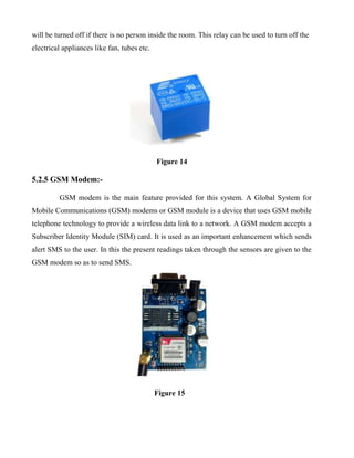
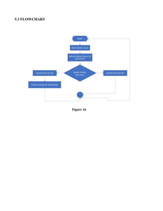
The document is a project report for an IoT-based smoke detection system. It describes the hardware and software components used in the system, including an MQ2 smoke sensor, Arduino Uno, GSM modem, LCD display, buzzer, relays, and ThingSpeak as the IoT platform. The system detects smoke using the sensor and sends an alert to ThingSpeak. Authorized users can then monitor the system status online. The report outlines the motivation to develop a modern alternative to traditional smoke detection that allows remote monitoring over the Internet of Things.


![2.2 REVIEW:
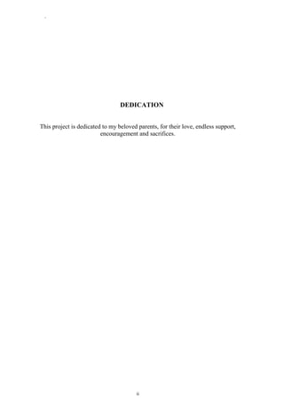
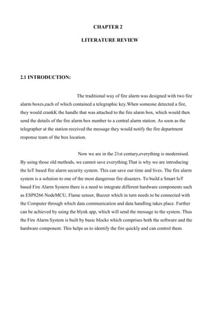
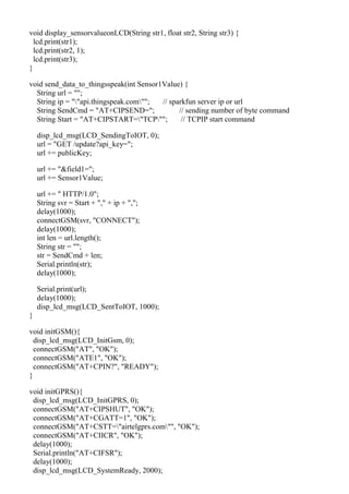
In [1], the research on fire using fire alarm systems is discussed.
In [3], Fire Behaviour and Fire line Safety is discussed.In [5], Review on Forest Fire Detection
using sensors is discussed. In [7], Forest Fire Smoke Video Detection Using Spatiotemporal and
Dynamic Texture is discussed. In [10], Multilayer Neural Network Based Fall Alert System
Using IOT is discussed. In this paper, we introduce Node MCU instead of Arduino. It will
consume less power from the source](https://image.slidesharecdn.com/cscproject-231223115507-7c501f07/85/csc-project-docx-12-320.jpg)
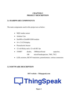

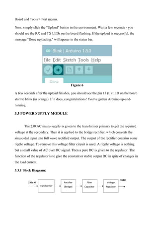

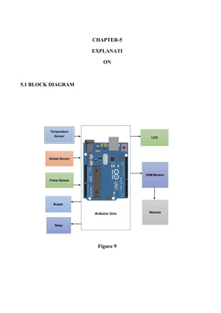


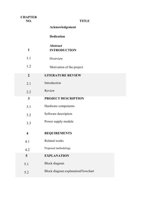
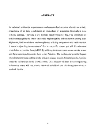
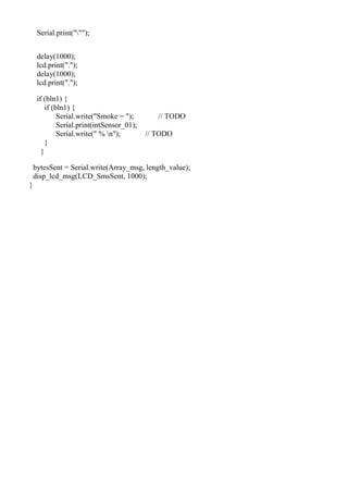
![6.2 SOURCE CODE
#include <LiquidCrystal.h>
LiquidCrystal lcd(5, 6, 7, 8, 9, 10);
int RED_Led = 11;
int Relay = 4;
int Buzzer = 3;
int sensorPin_01 = A0;
int Threshold_01 = 25;
// IOT Details
String publicKey = "ZC5AQJC4TOXCG4UE";
// LCD display messages
char LCD_WelcomeMsg[] = {"IOT SMOKE@DETECTOR SYSTEM$"};
char LCD_InitGsm[] = {"INITIALISING@GSM MODEM $"};
char LCD_InitGPRS[] = {"INITIALISING@GPRS PLZ WAIT $"};
char LCD_SystemReady[] = {"GSM MODEM@IS READY $"};
char LCD_SendingData[] = {"SENDING DATA TO@IOT $"};
char LCD_msgDataSent[] = {"DATA SENT TO IOT $"};
char LCD_GSMinit[] = {"Intialising Plz @wait $"};
char LCD_Poweron_Msg[] = {"SENDING POWERON @SMS........ $"};
char LCD_SendingToIOT[] = {"SENDING DATA@TO IOT$"};
char LCD_SentToIOT[] = {"DATA SENT@ TO IOT$"};
char LCD_SensorCommon[] = {"@SENSOR CROSSED$"};
char LCD_SendingSMS[] = {" SENDING @ SMS $"};
char LCD_SmsSent[] = {"SMS SENT@SUCCESSFULLY$"};
//SMS messages
char SMS_Welcome[] = {"IOT based Smoke monitoring system using Arduino."};
// TODO
char SMS_SensorCommon[] = {"Sensor crossed threhold level. Please take immediate
action. "};
float intSensor_01;
void func_Send_SMS(char *, int, bool);
String MobileNumber1 = "+917010267213";
void setup() {
pinMode(Relay, OUTPUT); //initialize pins as outputs
pinMode(Buzzer, OUTPUT); //initialize pins as outputs
pinMode(RED_Led, OUTPUT); //initialize pins as outputs
Serial.begin(9600); // init Serial1 for GSM
lcd.begin(16, 2); // init LCD
disp_lcd_msg(LCD_WelcomeMsg, 2000);](https://image.slidesharecdn.com/cscproject-231223115507-7c501f07/85/csc-project-docx-31-320.jpg)
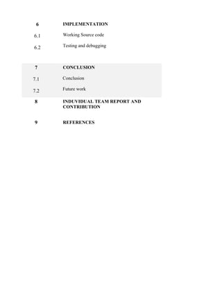
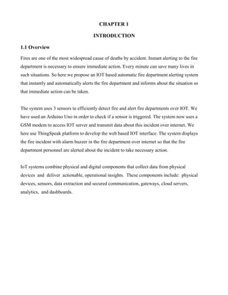
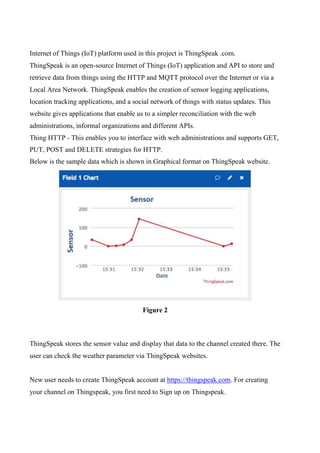
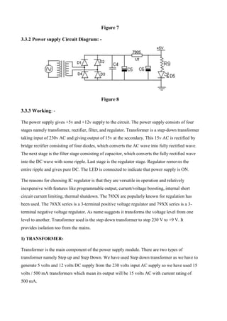
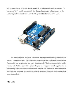
![}
void connectGSM (String cmd, char *res){
while (1)
{
Serial.println(cmd);
delay(500);
while (Serial.available() > 0)
{
if (Serial.find(res))
{
delay(1000);
return;
}
}
delay(1000);
}
}
void disp_lcd_msg(const char * LCD_Line, int intDelayTime) {
int i = 0;
lcd.clear();
while (LCD_Line[i] != '$') {
if (LCD_Line[i] == '@')
lcd.setCursor(0, 1); // set the cursor to column 0, line 1 // (note: line 1 is the second
row, since counting begins with 0):
else
lcd.print(LCD_Line[i]); // Print a message to the LCD.
i++;
}
if (intDelayTime != 0)
delay(intDelayTime);
}
void func_Send_SMS(char * Array_msg, int length_value, bool bln1) {
int bytesSent;
bytesSent = Serial.write("AT");
delay(2000);
disp_lcd_msg(LCD_SendingSMS, 0);
lcd.setCursor(9, 1);
bytesSent = Serial.write("AT+CMGF=1");
delay(1000);
lcd.print(".");
delay(1000);
lcd.print(".");
Serial.print("AT+CMGS="");
Serial.print(MobileNumber1);](https://image.slidesharecdn.com/cscproject-231223115507-7c501f07/85/csc-project-docx-34-320.jpg)


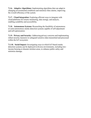

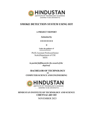
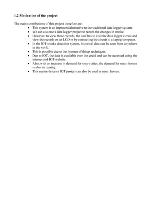
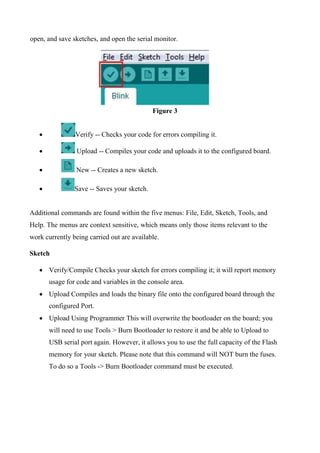
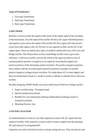
![CHAPTER 9
REFERENCES
[1] Breejen E. D. et al 2003–2012 In Proceedings of 3rd International Conference on Forest
Fire Research and 14thConference on Fire and Forest Meteorology (Luso,
Portugal)Autonomous forest fire detection 16-20.
[2] Hartung C. and Han R. 2006 Fire WxNet: A Multi Environments
4thInternational Conference of Mobile Systems, Applications and Services.
[3] Viegas D.X. 1993 Fire Behaviour and Fire line Safety Annual Mediterranean Burns
Club 6.
[4] Scott J. H. 2012 Introduction to Wildfire Behaviour Modelling
National Interagency Fuels, Fire and Vegetation Technology, Wildland Fire Management
RD&A.
[5] Alkhatib A. A. A. 2014 A Review on Forest Fire Detection
Techniques International Journal of Distributed Sensor Networks Article
ID: 597368.
[6] Vicente F. B., Carbajal N., Felipe L. and Martínez L. P. 2014 Estimation of Total Yearly
CO2 Emissions by Wildfires in Mexico during the Period 1999-2010 Advances in
Meteorology Article ID: 958457, 2014.
[7] Zhao Y., Zhou Z. and Xu M. 2015 Forest Fire Smoke Video Detection Using
Spatiotemporal and Dynamic Texture Features Journal of Electrical and
Computer Engineering Article ID: 706187, 2015.
[8] Vijayabaskar V. and Rajendran V. 2010 Analysis and modelling of wind dependence
of ambient noise in shallow water of Arabian sea European Journal of Scientific Research
50 28-34 SJR IF: 0.21, Nov.
[9] Manjula P. and Balachandra P. Information and Communication Technology
for Sustainable Development. Lecture Notes in Networks and Systems 9 ed D.
Mishra,
M. Nayak and A. Joshi (Singapore:Springer) An Analysis on Pricing Strategies of
Software ‘I-Med’ in Healthcare Industry.
[10] Shahada SA, Hreiji SM, Atudu SI and Shamsudheen S 2019 Multilayer Neural
Network Based Fall Alert System Using IOT International Journal of MC Square
Scientific Research 11 1-5.](https://image.slidesharecdn.com/cscproject-231223115507-7c501f07/85/csc-project-docx-41-320.jpg)