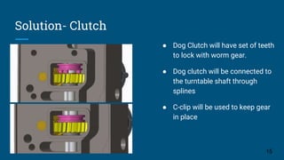
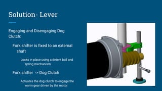
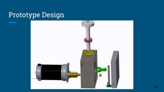
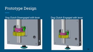
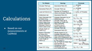
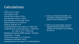
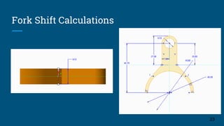
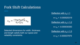
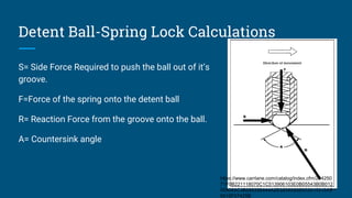
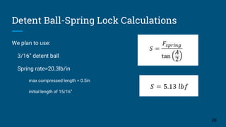
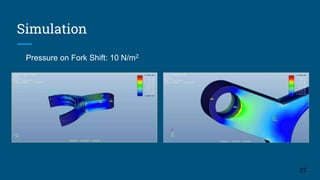
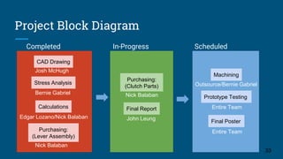
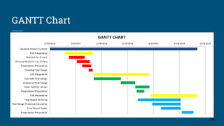
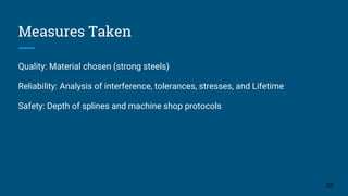
Critical Design Review:
Integrated Designs
Team 14:
Team Lead: John Leung,
Solution Analyst: Edgar Lozano,
Safety Officer: Bernie Gabriel
Chief Financial Officer: Nicholas Balaban
Cad Designer: Josh McHugh
1
Mission Statement
Integrated Designs aims to create a functional and viable solution to Cal Weld’s
Position welder by incorporating a system to engage and disengage the
turntable. Our project plans to assist the welders for a more comfortable and
efficient way of working to provide their consumers with quality products.
2
Table of Contents
I. Project Background
II. Project Plan
III.Prototype Design Concept
IV.Design Analysis
V.Project Schedule
3
I.Project Background
4
About Universal Calweld
● Been around for over 35 years located in Fremont, California
● Designs high purity components, subsystems, and components
● Provide manufacturing and engineering service to a variety of industries
5
Project Background
Sponsor: Greg Rozema
Faculty Advisor: Ala Qattawi
Design Challenge:
● Skilled workers from Cal Weld
need precision equipment
(Turntables) to weld components
● High Precision and purity welds
used for semiconductors and
production
6
http://www.mkproducts.com/support/Ma
nuals/091-
0677D_CobraTurn_DigTurntable_Lores.
Project Background
Cobra Digital Turntable Framework
http://www.mkproducts.com/support/Manuals/091-
0677D_CobraTurn_DigTurntable_Lores.pdf
7
Constraints/Requirements
http://www.mkproducts.com/support/Manuals/091-
0677D_CobraTurn_DigTurntable_Lores.pdf
● Cannot redesign the entire
system because of the cost
● Integrated clutch must fit within
the given housing assembly
● Design has to be cost effective
8
Design Constraints/Requirements
● Given width for worm gear
housing: 56.3mm
● Given length for worm gear
housing: 34.5mm
● Given depth for worm gear
housing: 50mm
9
Objective
● Current Turntable lacks a
mechanism or clutch that
disengages the turntable.
● Our design must not interfere
with the welding process and
maintain free mobility
● Must also satisfy all constraints
"The Engineering Design Process." The Engineering Design
Process. N.p., n.d. Web. 20 Feb. 2016.
<http://www.sciencebuddies.org/engineering-design-
process/engineering-design-process-steps.shtm
10
II: Project Plan
11
Why solution one wasn’t chosen
12
● Difficult to maintain overtime
● Isn’t user friendly because of
constant movement of the motor
● Orientation of worm makes
solution not possible
Why solution two was chosen
"LEGO Technic Transmission Driving Ring and Clutch Gear." YouTube.
YouTube, n.d. Web. 20 Feb. 2016.
<https://www.youtube.com/watch?v=mMsUIhGick0>.
● User friendly by using lever rod
to shift gear
● Practical way to disengage the
motor
● Minimal and simple
maintenance
13
Solution- Implementation
Dog Clutch will be implemented
above the worm gear
Sharing the same shaft
The shifter fork assembly will be on
a shaft parallel to the dog clutch
shaft.
14
Solution- Clutch
Picture of how the dog-clutch will look like
● Dog Clutch will have set of teeth
to lock with worm gear.
● Dog clutch will be connected to
the turntable shaft through
splines
● C-clip will be used to keep gear
in place
15
Solution- Lever
Engaging and Disengaging Dog
Clutch:
Fork shifter is fixed to an external
shaft
Locks in place using a detent ball and
spring mechanism
Fork shifter -> Dog Clutch
Actuates the dog clutch to engage the
worm gear driven by the motor 16
III: Prototype Design
Concept
17
Prototype Design
18
Prototype Design
Dog Clutch Disengaged with lever
19
Dog Clutch Engaged with lever
IV: Design Analysis
20
Calculations
● Based on our
measurements at
CalWeld
21
Calculations
22
Lead of worm: 5.3mm
Lead angle (γ): 3.86 °
Circular Pitch of Worm- 5.3mm
Pitch Diameter of Worm - 25mm
Pitch Diameter of Worm Gear- 45mm
Sliding Velocity (Vs): 51.64 ft/min
Pressure angle (ϕ)- 14.5°
Tangential speed of worm gear (VG): 4.642 ft/min
Tangential force on worm gear (WG
t ): 11468.45 lbf
WG
t with nd of 1.2: 13762.14 lbf
Reliability assumed by AGMA equation: 12hrs/day,
5days/week ---- 8 years
Torque at worm gear (TG): 31.90 lbs*in
Horsepower of the Motor: 0.8 Hp
Diametral pitch for worm gear (Pt ): 0.4444 teeth/mm
● Using our measurements taken, we
were able to understand the dynamic
system we are interacting with.
● With our new gear design, we aim to
replicate these parameters with the
creation of a new gear or by modifying
the old one
Fork Shift Calculations
23
Fork Shift Calculations
Deflection with nd = 1
● xsl = -0.000025319
Deflection with nd = 1.2
● xsl = -0.000030383
Deflection with nd = 1.5
● xsl = -0.000037979
24
Selected dimensions for width, thickness
and length satisfy both our space and
reliability constraints.
Detent Ball-Spring Lock Calculations
S= Side Force Required to push the ball out of it’s
groove.
F=Force of the spring onto the detent ball
R= Reaction Force from the groove onto the ball.
A= Countersink angle
25
https://www.carrlane.com/catalog/index.cfm/294250
71F0B221118070C1C513906103E0B05543B0B012
009083C3B285356444A2D020609090C0015312A3
6515F57425B
We plan to use:
3/16” detent ball
Spring rate=20.3lb/in
max compressed length = 0.5in
initial length of 15/16”
26
Detent Ball-Spring Lock Calculations
Simulation
27
Pressure on Fork Shift: 10 N/m2
Simulation Analysis
The deflection of the fork
Negligible
Area of the fork shift near the shaft
Area will experience the most stress and wear on the fork
Maintenance discretion:
Replace fork shift
Machine the cracks
28
Prototype Equipment List
● Dog Clutch
● New Worm Gear
● Fork Shift
● Shaft for Fork
● Plate for Lever Assembly
● Detent ball/Spring
● C-clips 29
Cost Analysis
● 6061 Aluminum Plate Stock. 1”x6”x6” $69.40
● 304 Stainless Steel Plate Stock. ⅜”x6”x6” $59.90
● 302 Stainless Steel Precision Ball. 3/16” Diam. $9.66 (pack of 100)
● Compression Spring. 20.3 lb/in.
$16.22
● 316 Stainless Steel Rod. ⅜” Diam. 1’ L $3.41
● Retaining Ring. Bore Diam 20mm $5.26
30
Economy to Scale
31
V: Project Schedule
32
Project Block Diagram
Completed
33
In-Progress Scheduled
CAD Drawing
Stress Analysis
Calculations
Purchasing:
(Lever Assembly)
Purchasing:
(Clutch Parts)
Final Report
Machining
Prototype Testing
Josh McHugh
Bernie Gabriel
Nick Balaban
Edgar Lozano/Nick Balaban
Nick Balaban
John Leung
Outsource/Bernie Gabriel
Entire Team
Final Poster
Entire Team
GANTT Chart
34
Measures Taken
Quality: Material chosen (strong steels)
Reliability: Analysis of interference, tolerances, stresses, and Lifetime
Safety: Depth of splines and machine shop protocols
35
Questions?
36
http://gph.is/1gSo4RG

Critical Design Review- Integrated Designs

  • 1.
    Critical Design Review: IntegratedDesigns Team 14: Team Lead: John Leung, Solution Analyst: Edgar Lozano, Safety Officer: Bernie Gabriel Chief Financial Officer: Nicholas Balaban Cad Designer: Josh McHugh 1
  • 2.
    Mission Statement Integrated Designsaims to create a functional and viable solution to Cal Weld’s Position welder by incorporating a system to engage and disengage the turntable. Our project plans to assist the welders for a more comfortable and efficient way of working to provide their consumers with quality products. 2
  • 3.
    Table of Contents I.Project Background II. Project Plan III.Prototype Design Concept IV.Design Analysis V.Project Schedule 3
  • 4.
  • 5.
    About Universal Calweld ●Been around for over 35 years located in Fremont, California ● Designs high purity components, subsystems, and components ● Provide manufacturing and engineering service to a variety of industries 5
  • 6.
    Project Background Sponsor: GregRozema Faculty Advisor: Ala Qattawi Design Challenge: ● Skilled workers from Cal Weld need precision equipment (Turntables) to weld components ● High Precision and purity welds used for semiconductors and production 6 http://www.mkproducts.com/support/Ma nuals/091- 0677D_CobraTurn_DigTurntable_Lores.
  • 7.
    Project Background Cobra DigitalTurntable Framework http://www.mkproducts.com/support/Manuals/091- 0677D_CobraTurn_DigTurntable_Lores.pdf 7
  • 8.
    Constraints/Requirements http://www.mkproducts.com/support/Manuals/091- 0677D_CobraTurn_DigTurntable_Lores.pdf ● Cannot redesignthe entire system because of the cost ● Integrated clutch must fit within the given housing assembly ● Design has to be cost effective 8
  • 9.
    Design Constraints/Requirements ● Givenwidth for worm gear housing: 56.3mm ● Given length for worm gear housing: 34.5mm ● Given depth for worm gear housing: 50mm 9
  • 10.
    Objective ● Current Turntablelacks a mechanism or clutch that disengages the turntable. ● Our design must not interfere with the welding process and maintain free mobility ● Must also satisfy all constraints "The Engineering Design Process." The Engineering Design Process. N.p., n.d. Web. 20 Feb. 2016. <http://www.sciencebuddies.org/engineering-design- process/engineering-design-process-steps.shtm 10
  • 11.
  • 12.
    Why solution onewasn’t chosen 12 ● Difficult to maintain overtime ● Isn’t user friendly because of constant movement of the motor ● Orientation of worm makes solution not possible
  • 13.
    Why solution twowas chosen "LEGO Technic Transmission Driving Ring and Clutch Gear." YouTube. YouTube, n.d. Web. 20 Feb. 2016. <https://www.youtube.com/watch?v=mMsUIhGick0>. ● User friendly by using lever rod to shift gear ● Practical way to disengage the motor ● Minimal and simple maintenance 13
  • 14.
    Solution- Implementation Dog Clutchwill be implemented above the worm gear Sharing the same shaft The shifter fork assembly will be on a shaft parallel to the dog clutch shaft. 14
  • 15.
    Solution- Clutch Picture ofhow the dog-clutch will look like ● Dog Clutch will have set of teeth to lock with worm gear. ● Dog clutch will be connected to the turntable shaft through splines ● C-clip will be used to keep gear in place 15
  • 16.
    Solution- Lever Engaging andDisengaging Dog Clutch: Fork shifter is fixed to an external shaft Locks in place using a detent ball and spring mechanism Fork shifter -> Dog Clutch Actuates the dog clutch to engage the worm gear driven by the motor 16
  • 17.
  • 18.
  • 19.
    Prototype Design Dog ClutchDisengaged with lever 19 Dog Clutch Engaged with lever
  • 20.
  • 21.
    Calculations ● Based onour measurements at CalWeld 21
  • 22.
    Calculations 22 Lead of worm:5.3mm Lead angle (γ): 3.86 ° Circular Pitch of Worm- 5.3mm Pitch Diameter of Worm - 25mm Pitch Diameter of Worm Gear- 45mm Sliding Velocity (Vs): 51.64 ft/min Pressure angle (ϕ)- 14.5° Tangential speed of worm gear (VG): 4.642 ft/min Tangential force on worm gear (WG t ): 11468.45 lbf WG t with nd of 1.2: 13762.14 lbf Reliability assumed by AGMA equation: 12hrs/day, 5days/week ---- 8 years Torque at worm gear (TG): 31.90 lbs*in Horsepower of the Motor: 0.8 Hp Diametral pitch for worm gear (Pt ): 0.4444 teeth/mm ● Using our measurements taken, we were able to understand the dynamic system we are interacting with. ● With our new gear design, we aim to replicate these parameters with the creation of a new gear or by modifying the old one
  • 23.
  • 24.
    Fork Shift Calculations Deflectionwith nd = 1 ● xsl = -0.000025319 Deflection with nd = 1.2 ● xsl = -0.000030383 Deflection with nd = 1.5 ● xsl = -0.000037979 24 Selected dimensions for width, thickness and length satisfy both our space and reliability constraints.
  • 25.
    Detent Ball-Spring LockCalculations S= Side Force Required to push the ball out of it’s groove. F=Force of the spring onto the detent ball R= Reaction Force from the groove onto the ball. A= Countersink angle 25 https://www.carrlane.com/catalog/index.cfm/294250 71F0B221118070C1C513906103E0B05543B0B012 009083C3B285356444A2D020609090C0015312A3 6515F57425B
  • 26.
    We plan touse: 3/16” detent ball Spring rate=20.3lb/in max compressed length = 0.5in initial length of 15/16” 26 Detent Ball-Spring Lock Calculations
  • 27.
  • 28.
    Simulation Analysis The deflectionof the fork Negligible Area of the fork shift near the shaft Area will experience the most stress and wear on the fork Maintenance discretion: Replace fork shift Machine the cracks 28
  • 29.
    Prototype Equipment List ●Dog Clutch ● New Worm Gear ● Fork Shift ● Shaft for Fork ● Plate for Lever Assembly ● Detent ball/Spring ● C-clips 29
  • 30.
    Cost Analysis ● 6061Aluminum Plate Stock. 1”x6”x6” $69.40 ● 304 Stainless Steel Plate Stock. ⅜”x6”x6” $59.90 ● 302 Stainless Steel Precision Ball. 3/16” Diam. $9.66 (pack of 100) ● Compression Spring. 20.3 lb/in. $16.22 ● 316 Stainless Steel Rod. ⅜” Diam. 1’ L $3.41 ● Retaining Ring. Bore Diam 20mm $5.26 30
  • 31.
  • 32.
  • 33.
    Project Block Diagram Completed 33 In-ProgressScheduled CAD Drawing Stress Analysis Calculations Purchasing: (Lever Assembly) Purchasing: (Clutch Parts) Final Report Machining Prototype Testing Josh McHugh Bernie Gabriel Nick Balaban Edgar Lozano/Nick Balaban Nick Balaban John Leung Outsource/Bernie Gabriel Entire Team Final Poster Entire Team
  • 34.
  • 35.
    Measures Taken Quality: Materialchosen (strong steels) Reliability: Analysis of interference, tolerances, stresses, and Lifetime Safety: Depth of splines and machine shop protocols 35
  • 36.

Editor's Notes

  • #34 Completed: Cad Drawings, Stress Analysis, calculations, Purchasing(lever assembly) In Progress: Purchasing(clutch parts), Final report Scheduled: Prototype testing, Machining