9. Fig 1- We will control the dog clutch by implementing a shifter fork ( in green) which only needs to slide
¼ of an inch to engage and disengage the gears.
Fig2- Demonstrates how the system will appear when it is engaged.
Fig3-Entire Turn Table Assembly
Fig4-exploded view of our design
-Fig5-Technical Drawing of our dog clutch
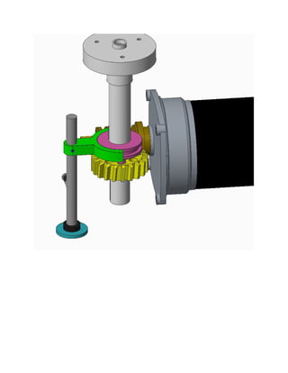
Fig6- The dog clutch will be actuated (by pulling down or pushing up) using the lever in light blue
Fig7- The grooves on the fork shifter lever, will act as a spring locking mechanism which will hold the
fork in place. They will slide into place and become self-locking after the gear is engaged or disengaged.
Fig8-Disengaged state, view with the housing included.
Fig9- The Worm drives the worm gear which is now free to rotate along the shaft without spinning the
turn table. Our Dog clutch is splined to the shaft, so when the system is engaged, it will then turn the
turntable.
10. Fig 10,11- Simulated stress distribution on shifter fork with pressure of 10 N/m^2