
![44
Safety
II. Main features
• Internal arc tested AFL[R]
• Gas insulated and screened system
• Mechanical and electrical interlocks to prevent unsafe operations
Reliability
• Gas insulated and sealed for life
• 100 % routine tested at factory
• Seismic tested
Efficiency
• Modular design extensible to both sides without gas handling
• Easy frontal access to install and to test MV cables and fuses
• Optimised dimensions
Sustainability
• No SF6 use during installation
• En-of-life management and recycling
• Investment in alternative materials and own technology
Continuous innovation
• Updated ratings: Up to 2500 A
• Voltage an current sensors for metering and protection
• Optional monitoring system to see the switch position inside the gas tank
cpg.0 & cpg.1](https://image.slidesharecdn.com/cpg-en-140801021442-phpapp02/85/cpg-system-4-320.jpg)
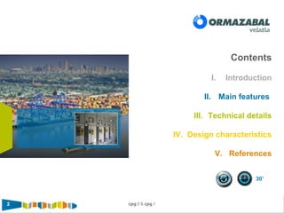
![6 cpg.0 & cpg.1
General ratings
III. Technical details
IEC ANSI / IEEE
cpg.0 cpg.1 cpg.0 cpg.1
Rated Voltage Ur [kV] 24 36 24 36 27 38 27 38
Rated frequency fr [Hz] 50 / 60 50 / 60
Rated normal current Ir
Busbars (max) [A] 2500 1250 2000 2250 1250 2000
Outgoing line [A] 2500 1250 2000 2250 1250 2000
Rated short-time withstand current
with tk = 1- 3 s Ik [kA] 25 25 / 31.5 25 25 / 31.5
Peak value (max) Ip [kA] 65 65 / 80 65 65 / 80
Rated insulation level
Rated power-frequency withstand
voltage [1 min]
Ud [kV] 50/
60
70/
80
80/
90
50/
66
8 /
88
60/
66
80/
88
Rated lightning impulse withstand
voltage
Up [kV] 125/
145
170/
195
180 /
210
125 /
145
170/
195
125/
145
170/
195
Internal arc classification according to
IEC 62271-200 (IEE Std C37.20,7)
IAC AFL[R] 25 kA 1s AFL 31.5 kA 1s AFL[R] 25 kA 1s AFL 31.5 kA 1s
Degree of protection IP IP3X
Loss of service continuity category LSC LSC2
Partition class PM](https://image.slidesharecdn.com/cpg-en-140801021442-phpapp02/85/cpg-system-6-320.jpg)
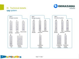
![7 cpg.0 & cpg.177
IV. Design characteristics
Constructive structure: cpg.0
General view
cpg.0-v
Width [mm] 600 800 1000
Depth [mm] 1365 1545
Height [mm] 2425 / 2225
Weight [kg] <750 <1100 <1200
1
4
2
3
5
Gas tank
Driving mechanism
and operator interface
Control box /
LV compartment
Busbar compartment
Cable compartment
1
4
2
3
5
Detailed view
1. Gas tank
1.1 Vacuum CB
1.2 Three-position
switch -
disconnector
1.3
Pressure relief
duct
2. Main
busbars
4. Cable compartment
4.1 Bushings
4.2 CT
4.3 VT
4.4 Phase segregation
4.5 Terminals
5. LV compartment
5.1 Protection & control
devices
3. Interface
1.Driving
mechanisms
2.Voltage presence
indicator
3. Mimic diagram
1
1.1
1.2
1.3
2
3
3.1
3.2
3.3
4.1
44.3
4.2
4.44.5
5
5.1](https://image.slidesharecdn.com/cpg-en-140801021442-phpapp02/85/cpg-system-7-320.jpg)
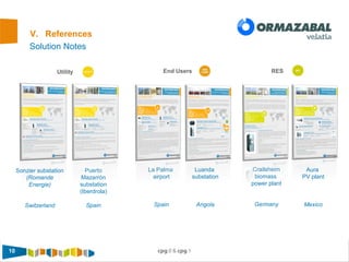
![8 cpg.0 & cpg.188
IV. Design characteristics
Constructive structure: cpg.1
General view
cpg.1 -v1 cpg.1-v2
Width [mm] 600
Depth [mm] 2004
Height [mm] 2725
Weight [kg] 1100 1400
1
4
2
3
5
Gas tanks
Driving mechanism
and operator interface
Control box /
LV compartment
Busbar compartment
Cable compartment
1
4
2
3
5
Detailed view
1. Gas tank/s
1.1 Vacuum CB
1.2 Disconnectors
1.3 Earthing
switch
1.4 Pressure relief
duct
2. Main
busbars
v1: single
v2: double
4. Cable compartment
4.1 Bushings
4.2 CT
4.3 VT
4.4 Phase segregation
4.5 Terminals
5. LV compartment
5.1 Protection & control
devices
3. Interface
3.1 Driving
mechanisms
3.2 Voltage presence /
absence indicator
3.3 Mimic diagram
1
1.1
1.2
1.3
2
3
3.1
3.2
3.3
4.1
44.3
4.2
4.44.5
5
5.1
1.4](https://image.slidesharecdn.com/cpg-en-140801021442-phpapp02/85/cpg-system-8-320.jpg)


The document details the specifications and features of the CPG single and double busbar panel type gas-insulated switchgear system, designed for primary distribution applications. It highlights the system's reliability, internal arc testing, and modular design, along with technical details such as voltage ratings, current capacities, and safety features. Additionally, it references various global project implementations and emphasizes sustainability through the absence of SF6 gas during installation.


![Attack surfaces and attack tress[inform]](https://cdn.slidesharecdn.com/ss_thumbnails/lecture03-260108015941-a4dee53b-thumbnail.jpg?width=640&height=640&fit=bounds)
