Downloaded 26 times


![leyboldOerlikon Leybold Vacuum
Catalog Part Vacuum Pump Systems, Edition 201314
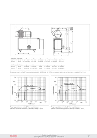
Oil Sealed RUTA Pump Systems
Two-Stage, with Single-Stage SOGEVAC Backing Pumps,
Adaptor Version
h
b
2l
c
h1
1l
l
DN2
2
b1
b
DN1
1
l b
h 2
DN2
1l
h
b
c
1b
l2
DN1
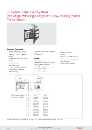
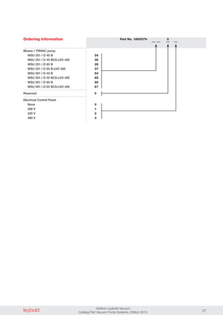
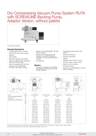
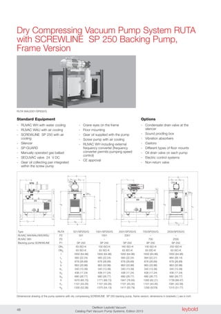
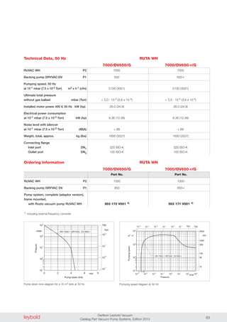
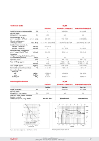
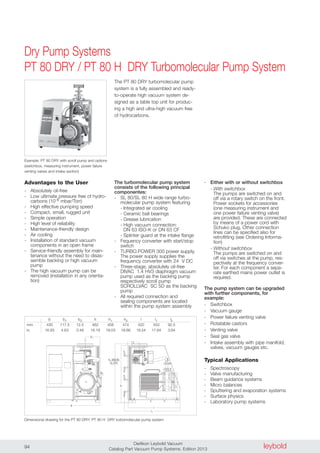
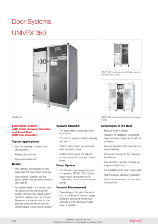
Standard Equipment
- Exhaust filter with oil return line
- Oil filter
- Oil collecting pan
- Gas ballast valve:
SV 200/300 B manually operated
SV 630 BF 24 V DC
- SV 200/300 B with air cooling
- SV 630 BF with water cooling
- Floor mounting
- The oil is supplied with the pump
- CE approval
Options
- Frequency converter
RUVATRONIC RT for controlling the
speed of the Roots pump
- 24 V DC gas ballast valve or
manually operated
- Sound proofing box
- Vibration absorbers
- Castors
- Different types of floor mounts
- Oil drain valve on each pump
- Special motors
- Electric control systems
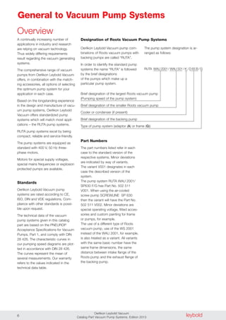
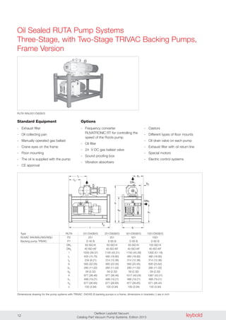
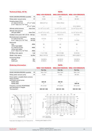
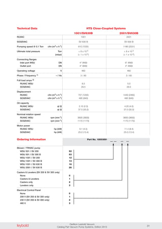
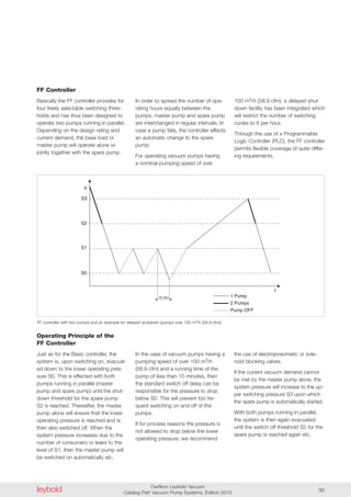
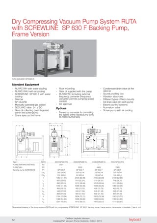
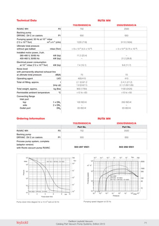
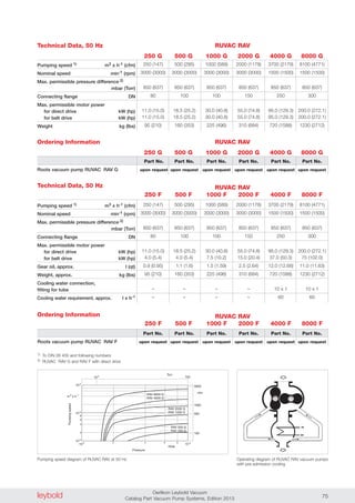
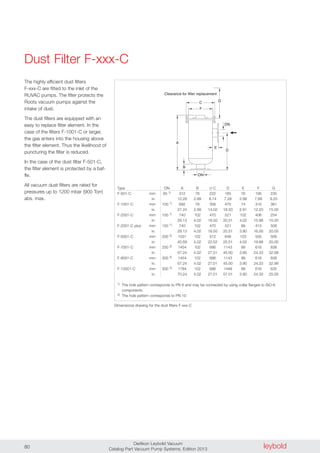
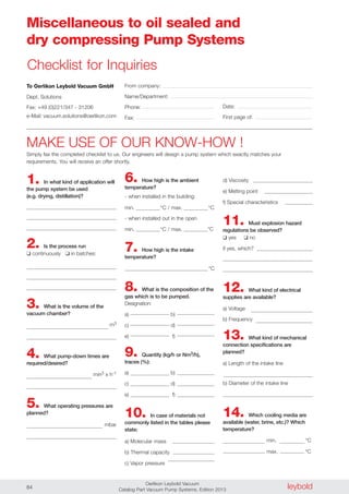
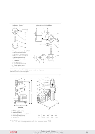
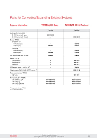
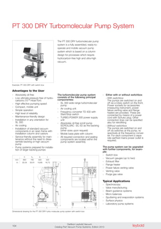
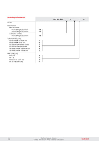
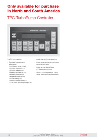
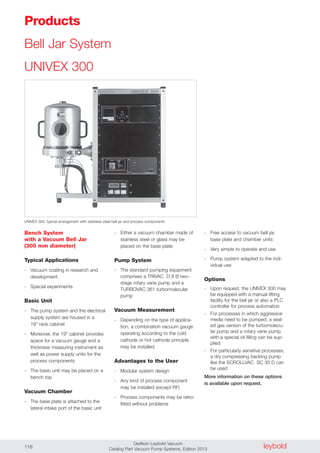
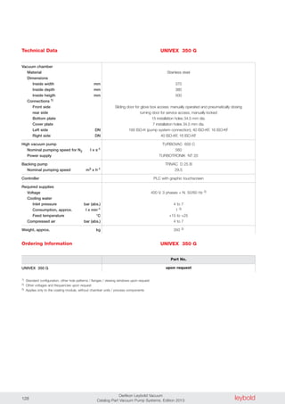
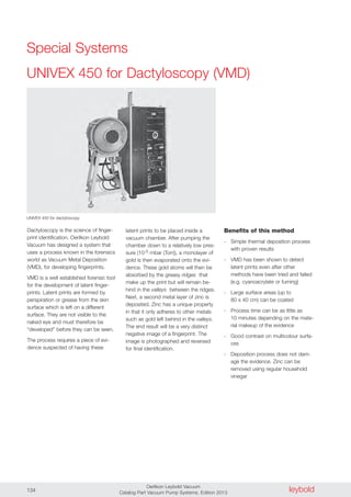
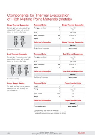
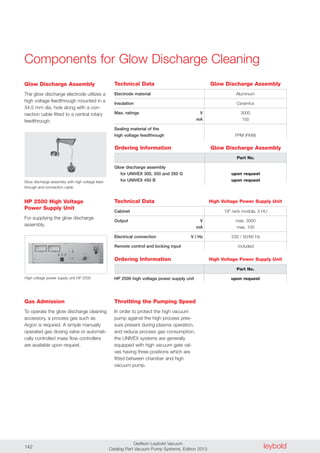
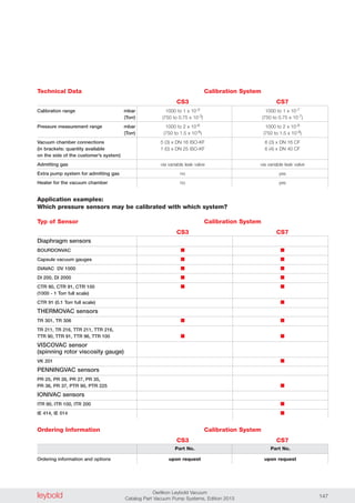
RUTA WAU1001/SV200/A
Type RUTA 501/SV200/A 1001/SV200/A 1001/SV300B/A 2001/SV630BF/A
RUVAC WA/WAU/WS/WSU P2 501 1001 1001 2001
Backing pump SOGEVAC P1 SV 200 SV 200 SV 300 B SV 630 BF
DN1 63 ISO-K 100 ISO-K 100 ISO-K 160 ISO-K
DN2 2" 2" 2" 100 ISO-K
l 962 (37.87) 1050 (41.34) 1030 (40.55) 1896 (74.65)
l1 242 (9.53) 303 (11.93) 298 (11.73) 987 (38.86)
l2 70 (2.76) 77 (3.03) 88 (3.47) 40 (1.56)
b 700 (27.56) 700 (27.56) 700 (27.56) 1000 (39.37)
b1 230 (9.06) 230 (9.06) 230 (9.06) 456 (17.95)
b2 499 (19.65) 499 (19.65) 520 (20.47) 764 (30.08)
h 873 (34.37) 923 (36.34) 929 (36.58) 1340 (52.76)
h1 468 (18.43) 468 (18.43) 480 (18.90) 720 (28.35)
c 100 (3.94) 100 (3.94) 100 (3.94) 100 (3.94)
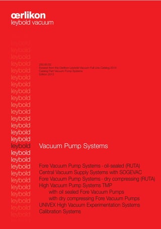
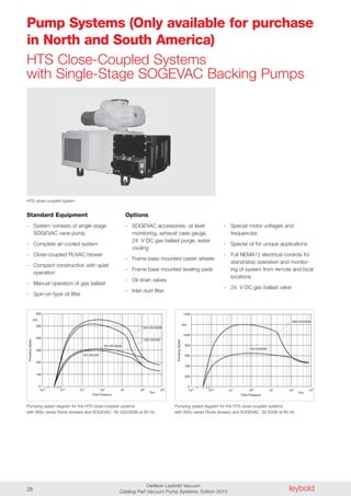
Dimensional drawing for the pump systems with SOGEVAC SV 200 and 300 B backing pumps [left], SOGEVAC SV 630 BF [right]; dimensions in brackets ( ) are in inch
Zeichnung in Arbeit
b
h
c
h
b
b
2
1
1DN
l
l
l
DN2
1
2
1](https://image.slidesharecdn.com/cp050en-vacuumpumpsystems-podsmall-141228133826-conversion-gate01/85/Cp-050-en-vacuum-pump-systems-pod_small-14-320.jpg)
![leyboldOerlikon Leybold Vacuum
Catalog Part Vacuum Pump Systems, Edition 201316
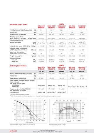
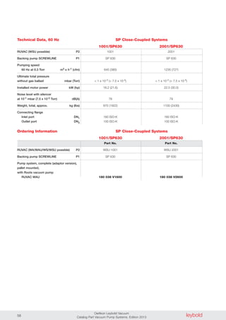
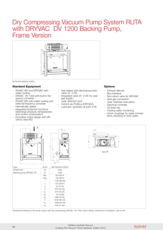
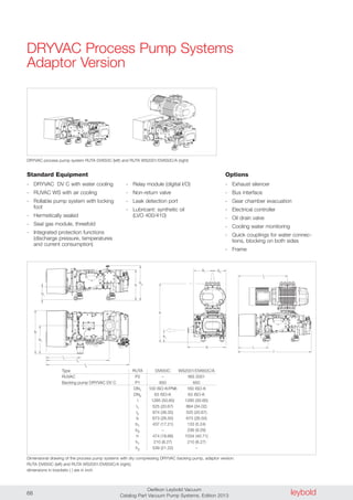
Oil Sealed RUTA Pump Systems
Two-Stage, with Single-Stage SOGEVAC Backing Pumps,
Adaptor Version
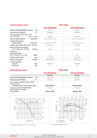
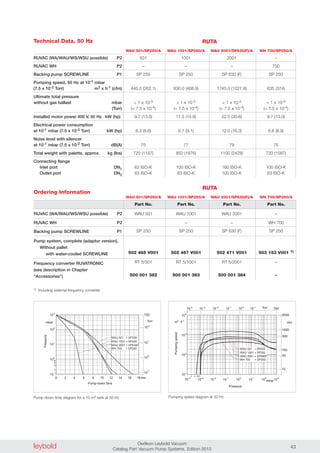
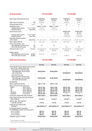
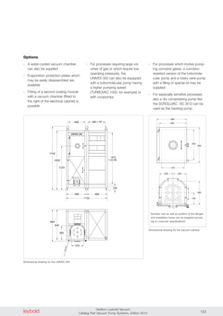
Standard Equipment
- RUVAC WH with water cooling
- Exhaust filter with oil return line
- Oil filter
- Oil collecting pan
- Gas ballast valve:
SV 100 to 300 manually operated
SV 630 BF 24 V DC
- SV 100 to 300 with air cooling
- SV 630 BF with water cooling
- Floor mounting
- The oil is supplied with the pump
- RUVAC WH including external
frequency converter (frequency
converter permits pumping speed
control)
- CE approval
Options
- 24 V DC gas ballast valve or
manually operated
- Sound proofing box
- Vibration absorbers
- Castors
- Different types of floor mounts
- Oil drain valve on each pump
- Special motors
- Electric control systems
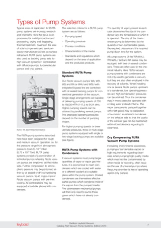
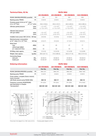
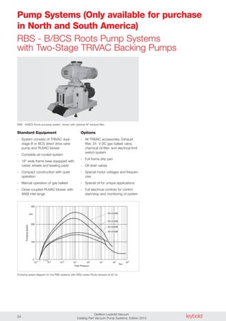
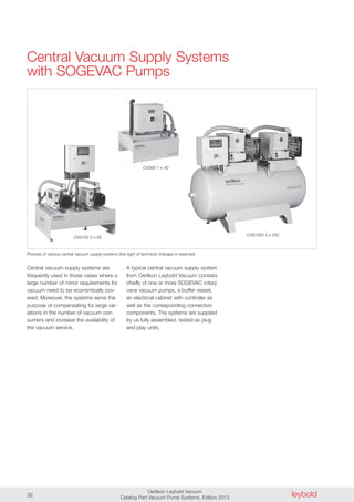
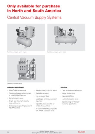
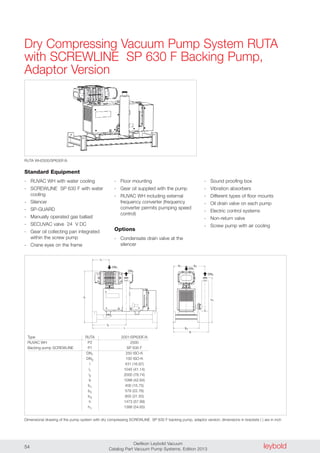
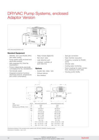
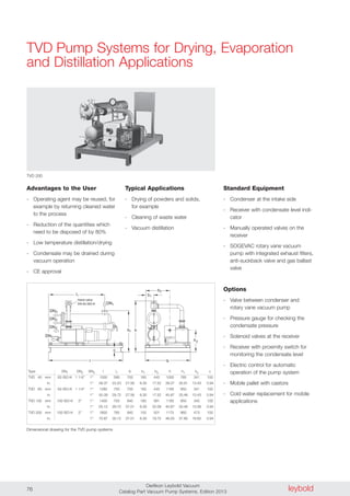
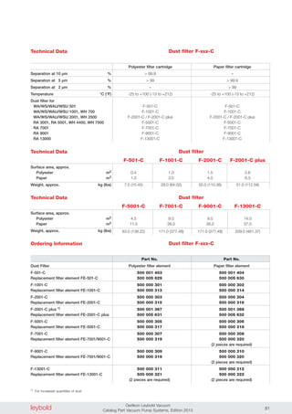
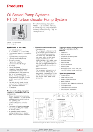
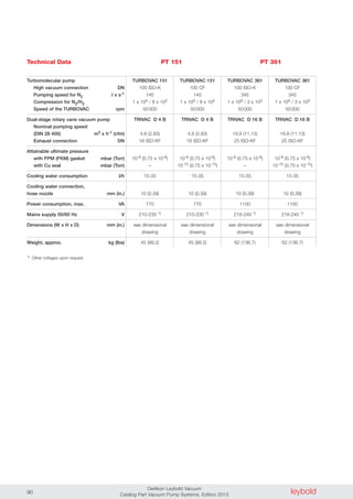
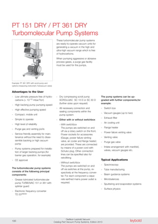
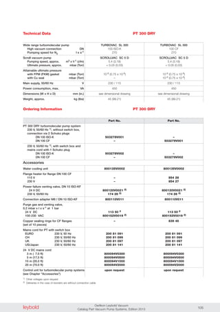
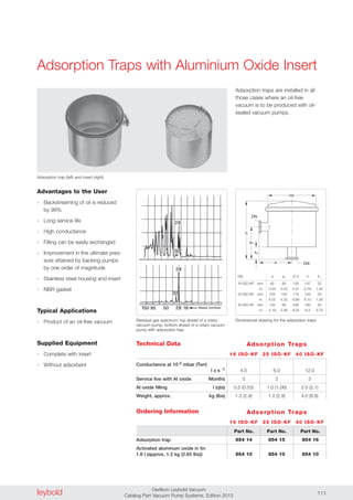
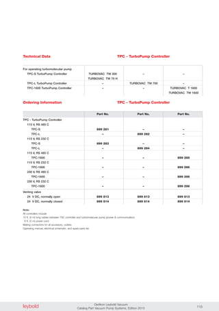
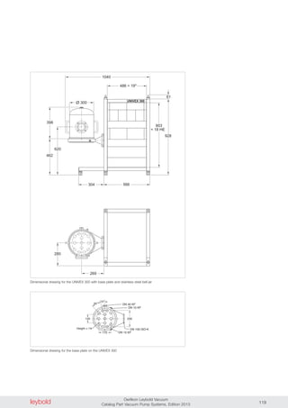
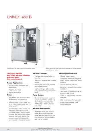
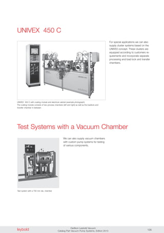
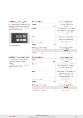
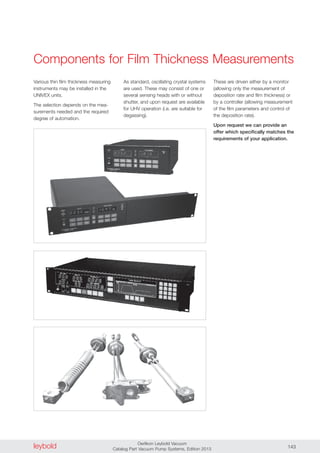
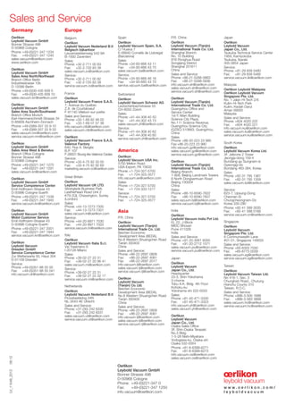
RUTA WH4400/SV630BF/A
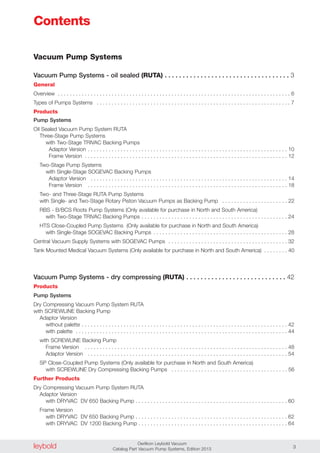
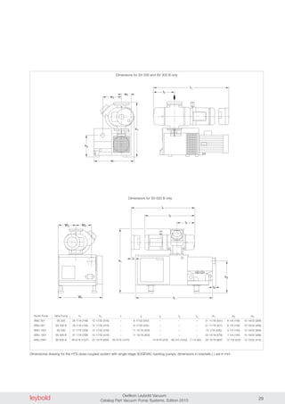
Dimensional drawing for the pump systems with SOGEVAC SV 100 B, 200 and 300 B backing pumps [left], SOGEVAC SV 630 BF [right];
dimensions in brackets ( ) are in inch
l
l2
l1
b
b2
b1
c
h
h1
l3
l4
DN1
DN2
Type RUTA 700/SV100B/A 700/SV200/A 700/SV300B/A 4400/SV630BF/A
RUVAC WH P2 700 700 700 4400
Backing pump SOGEVAC P1 SV 100 B SV 200 SV 300 B SV 630 BF
DN1 100 ISO-K 100 ISO-K 100 ISO-K 250 ISO-K
DN2 G 1 1/4" G 2" G 2" 100 ISO-K
l 710 (27.95) 950 (37.40) 950 (37.40) 1896 (74.65)
l1 217 (8.54) 262 (10.32) 335 (13.19) 947 (37.28)
l2 85 (3.35) 84 (3.31) 125 (4.92) 40.5 (1.59)
l3 41 (1.61) – 45 (1.77) –
l4 17 (0.67) – 95 (3.74) –
b 500 (19.69) 700 (27.56) 700 (27.56) 1000 (39.37)
b1 175 (6.89) 230 (9.06) 230 (9.06) 456 (17.95)
b2 384 (15.12) 499 (19.65) 520 (20.47) 764 (30.08)
c 100 (3.94) 100 (3.94) 100 (3.94) 100 (3.94)
h 708 (27.87) 829 (32.64) 827 (32.56) 1450 (57.09)
h1 365 (14.37) 468 (18.43) 480 (18.90) 720 (28.35)
l
b
h
h
b
b
l
l
DN2
1
2 2
1
1DN1](https://image.slidesharecdn.com/cp050en-vacuumpumpsystems-podsmall-141228133826-conversion-gate01/85/Cp-050-en-vacuum-pump-systems-pod_small-16-320.jpg)

![leybold Oerlikon Leybold Vacuum
Catalog Part Vacuum Pump Systems, Edition 2013 37
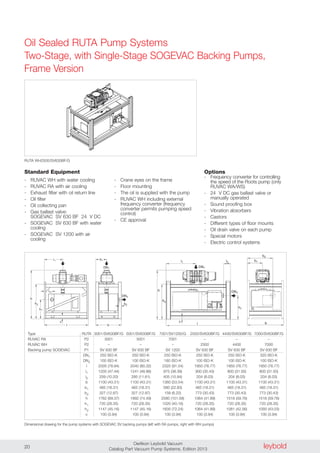
H
L W
H
L W
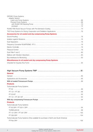
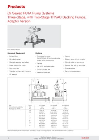
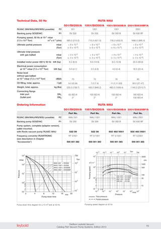
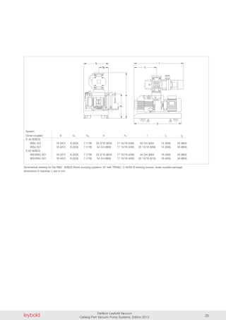
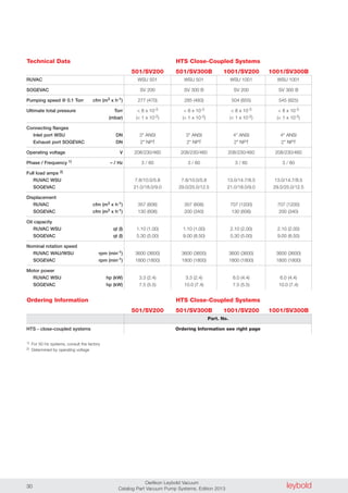
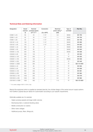
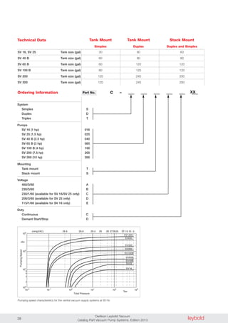
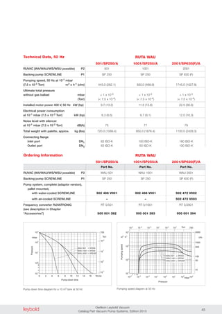
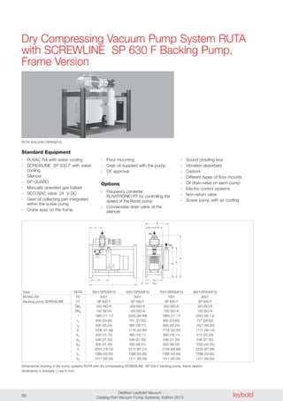
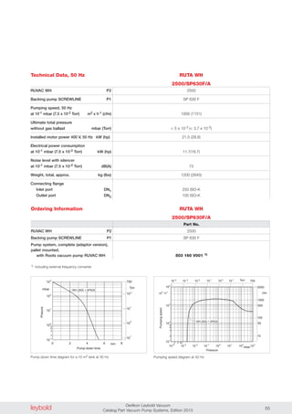
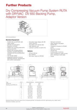
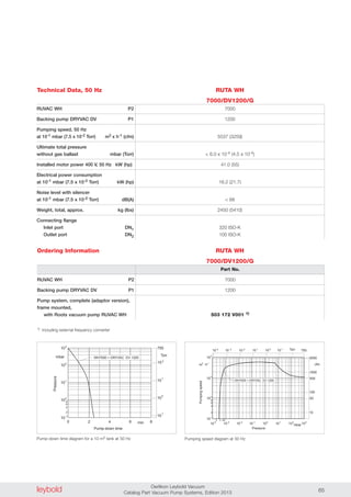
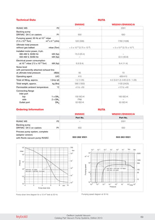
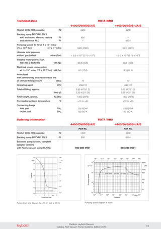
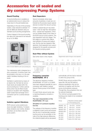
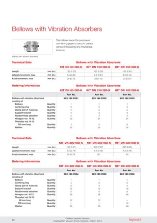
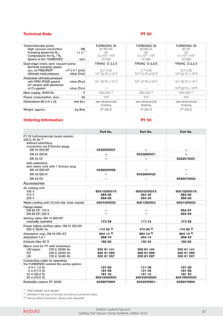
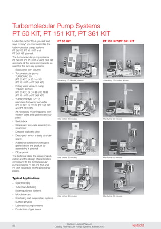
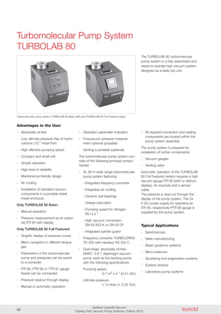
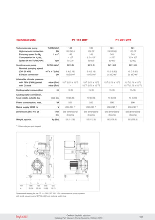
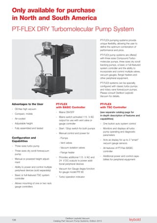
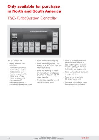
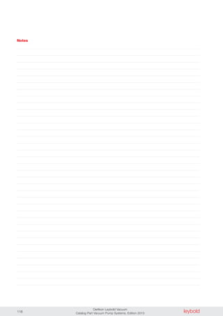
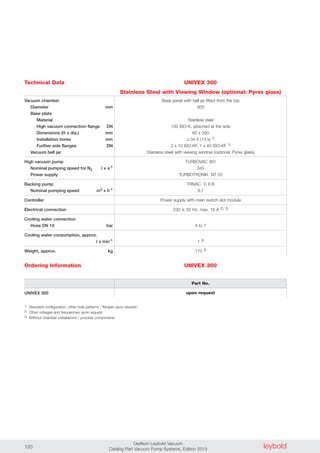
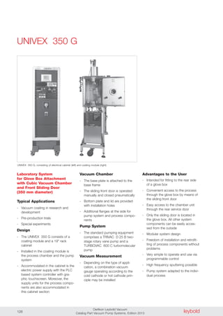
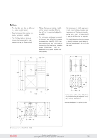
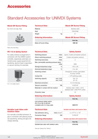
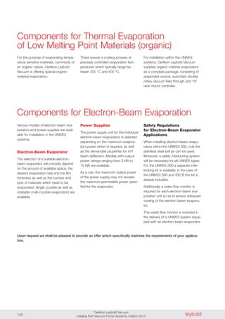
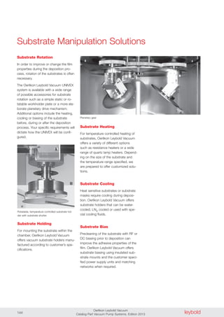
Central vacuum supply systems, tank mounted [left] and stack mounted [right]; dimensions in inch, dimensions in brackets ( ) are in mm
Pump model Tank size (gal) L W H
Tank mount - simplex
SV 16, SV 25 30 42 (1067) 20 (508) 51 (1295)
SV 40 B, SV 65 B 60 50 (1270) 25 (635) 48 (1219)
SV 100 B 80 65 (1651) 25 (635) 56 (1422)
SV 200, SV 300 120 70 (1778) 28 (711) 58 (1473)
Tank mount - duplex
SV 16, SV 25 60 50 (1270) 27 (686) 53 (1346)
SV 40 B, SV 65 B 80 65 (1651) 30 (762) 53 (1346)
SV 100 B 120 71 (1803) 32 (813) 53 (1346)
SV 200 240 84 (2134) 38 (965) 64 (1626)
SV 300 240 84 (2134) 43 (1092) 64 (1626)
Stack mount - duplex and triplex
SV 16, SV 25 60 45 (1143) 38 (965) 56 (1422)
SV 40 B 80 49 (1245) 42 (1067) 56 (1422)
SV 65 B 120 62 (1575) 45 (1143) 88 (2235)
SV 100 B 120 68 (1727) 42 (1067) 88 (2235)
SV 200 200 68 (1727) 50 (1270) 91 (1626)
SV 300 200 68 (1727) 58 (1473) 91 (1626)
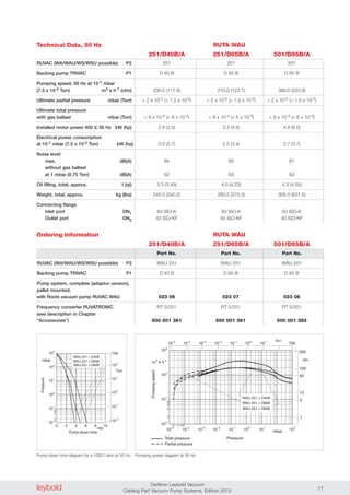
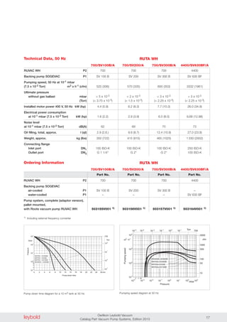
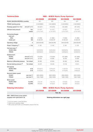
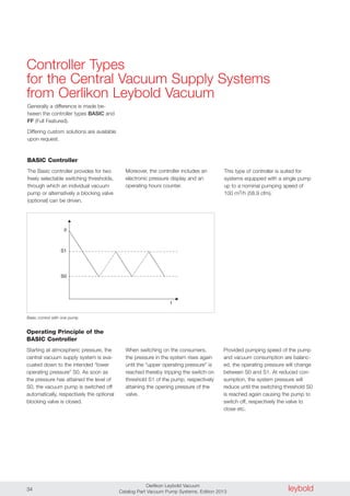
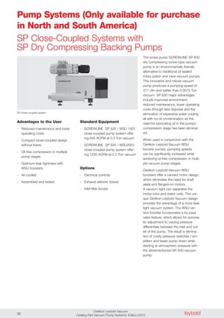
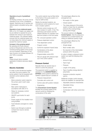
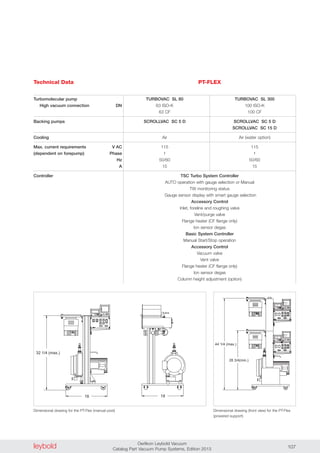
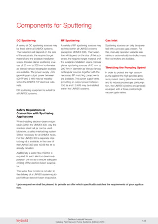
Technical Data
Free air displacement cfm (m3 x h-1)
Actual pumping speed cfm (m3 x h-1)
Guaranteed base pressure Torr
Base pressure with gas ballast Torr
Water vapor tolerance Torr
Water vapor pumping with gas ballast
qt/hr
Noise level at 3 feet with 1 pump
running without gas ballast dB(A)
Motor hp
Pump rotational speed rpm
Oil capacity qt
Inlet / exhaust - NPT in.
Pump weight lbs
11 (18.6) 17.0 (29.0) 31.2 (53.0) 41.8 (71.0) 68.9 (117.0) 129.5 (219.8) 200.3 (340.0)
10 (16.9) 15 (25.5) 27.7 (47.0) 37.7 (64.0) 61.8 (105.0) 117.8 (200.0) 170.8 (289.9)
0.4 0.4 0.4 0.4 0.4 0.06 0.06
1.1 1.1 1.1 1.1 1.0 0.5 0.5
30.0 30.0 22.5 22.5 22.5 30.0 30.0
0.32 0.48 0.95 1.32 1.8 5.7 7.8
56 56 63 64 64 73 74
1.0 1.5 2.0 2.5 4.0 7.5 10.0
1750 1500 1750 1750 1750 1750 1750
2.0 2.0 1.05 2.1 2.1 5.5 9.0
1/2 / 1/2 1/2 / 1/2 1-1/4 / 1-1/4 1-1/4 / 1-1/4 1-1/4 / 1-1/4 2 / 2 2 / 2
50.7 52.9 99.3 114.8 194.3 341.8 430.0
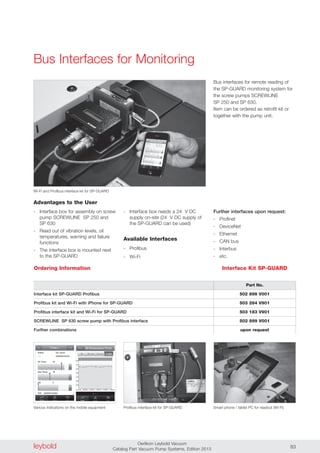
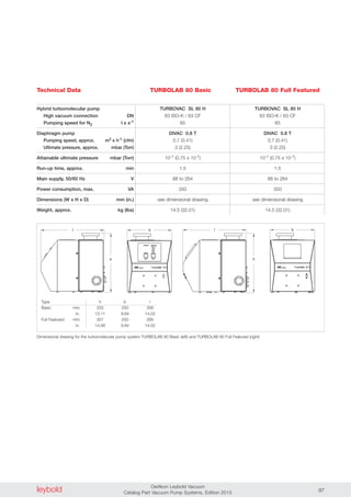
Performance Characteristics
SV 16 SV 25 SV 40 B SV 65 B SV 100 B SV 200 SV 300](https://image.slidesharecdn.com/cp050en-vacuumpumpsystems-podsmall-141228133826-conversion-gate01/85/Cp-050-en-vacuum-pump-systems-pod_small-37-320.jpg)


This document describes various vacuum pump systems from Oerlikon Leybold Vacuum. It includes systems that use oil-sealed and dry compressing fore vacuum pumps, as well as high vacuum pump systems that use turbomolecular pumps. The systems cover a range of applications from industrial coating to scientific experimentation. Details are provided on complete pump systems, individual pump models, accessories, and general information.


