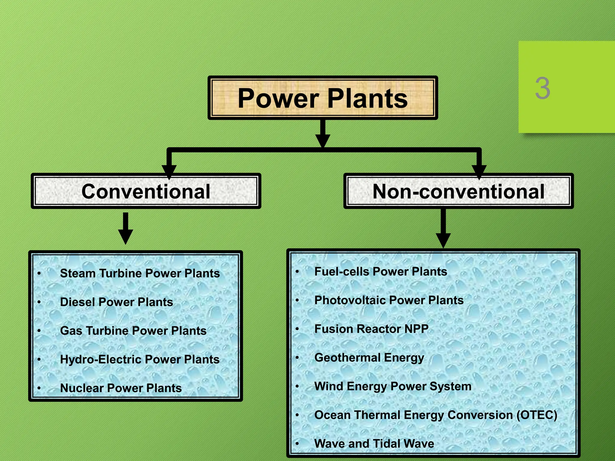
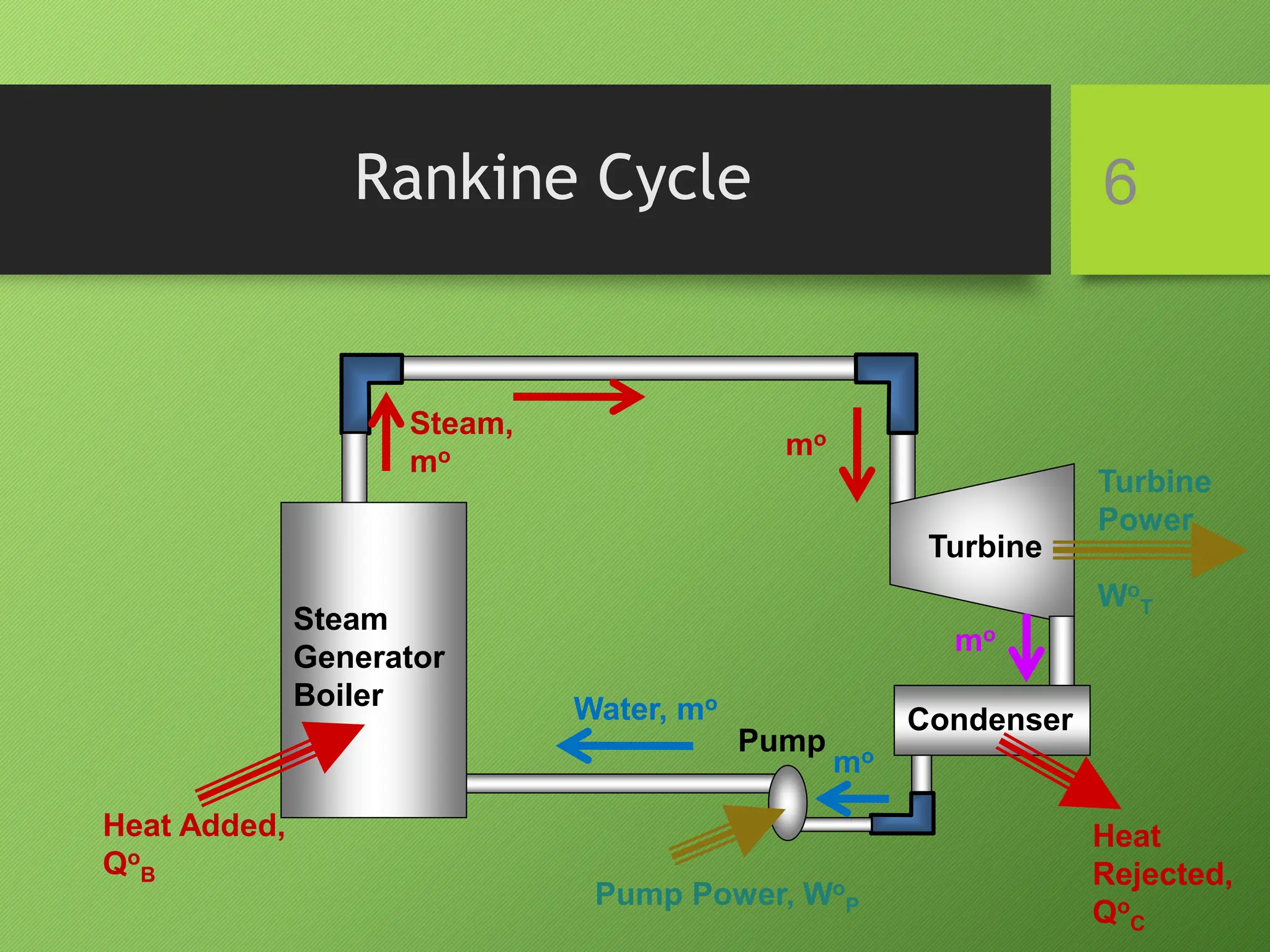
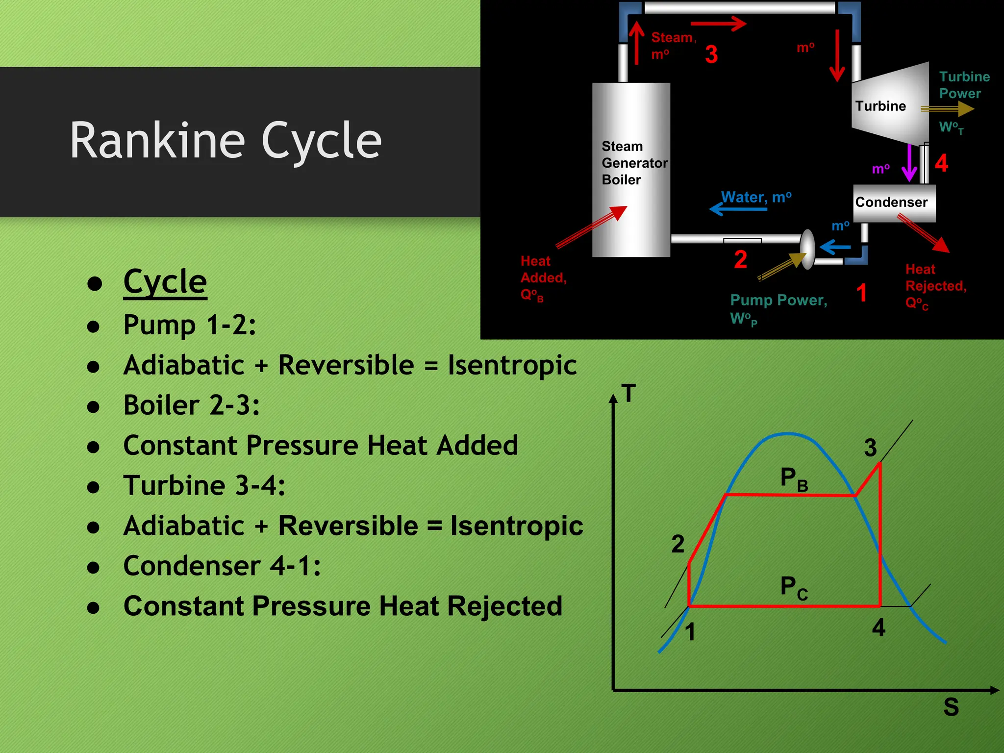
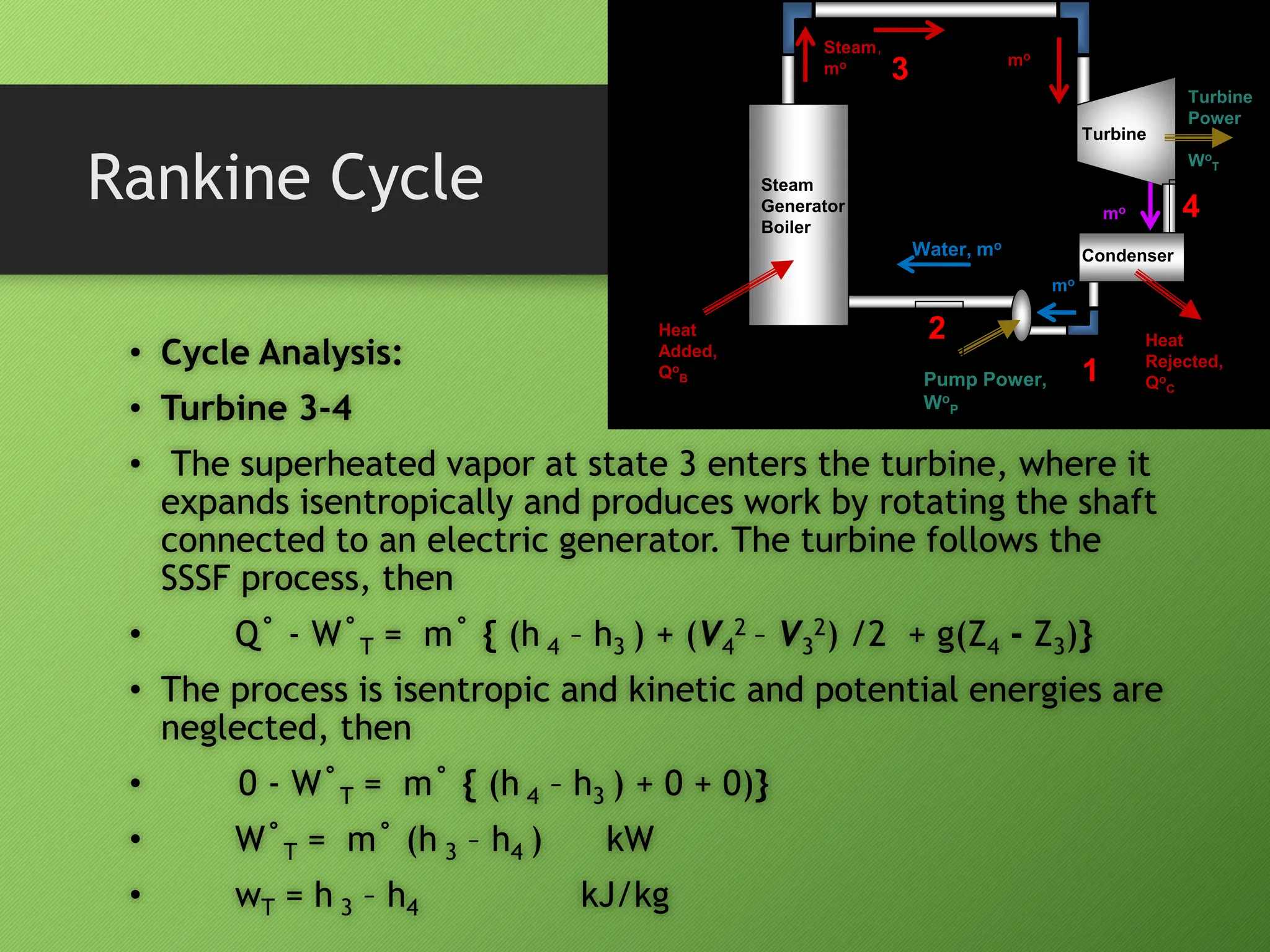
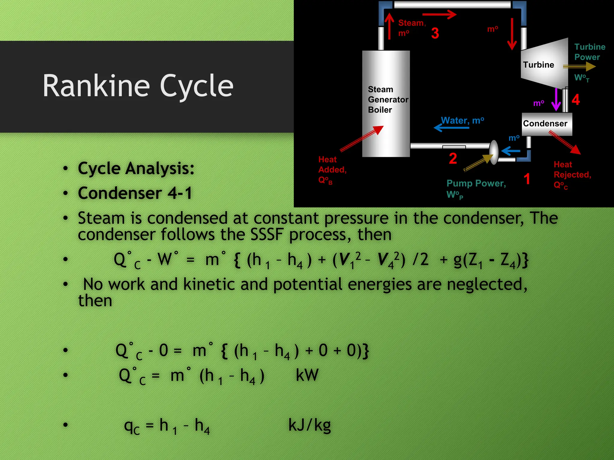
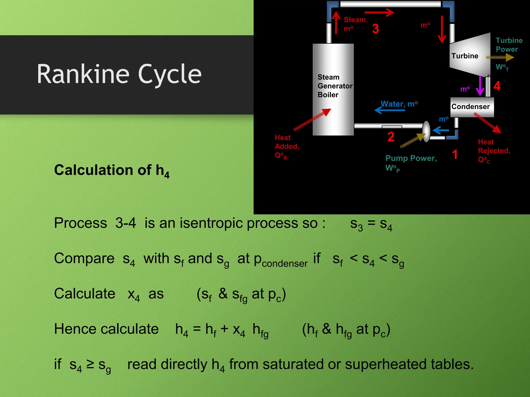
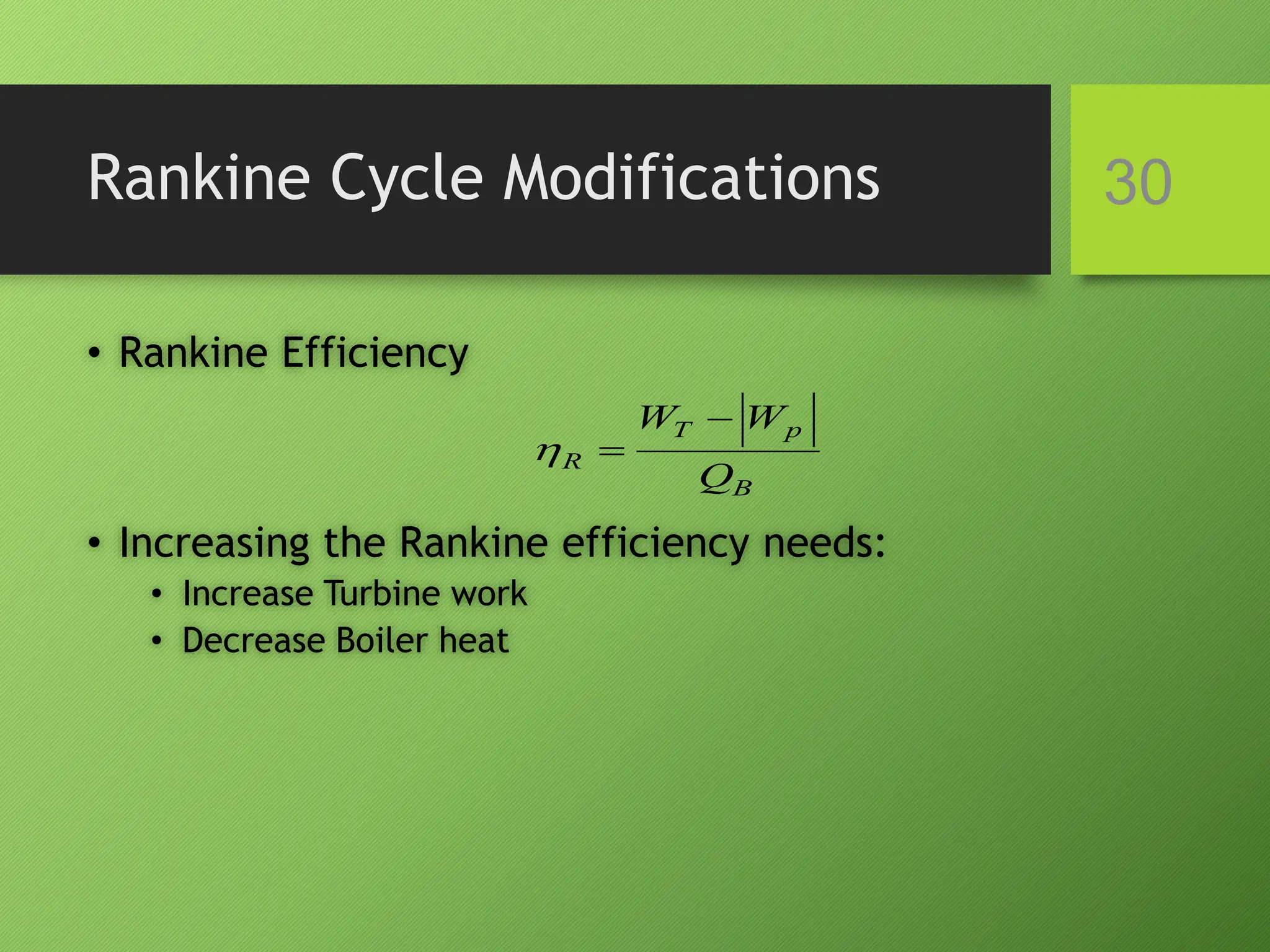
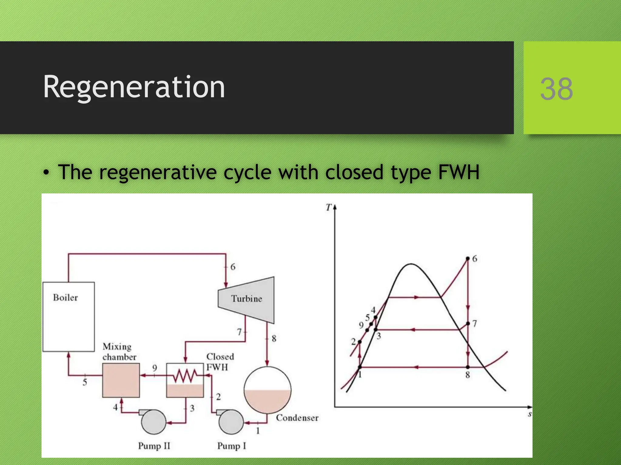
Conventional Thermal
Power Plants
• Mohamed F. Zayed
• Assistant Professor,
• Mechanical Power Engineering Department
• Cairo University
PEC417
POWER CYCLES 2
3
Conventional Non-conventional
Power Plants
• Steam Turbine Power Plants
• Diesel Power Plants
• Gas Turbine Power Plants
• Hydro-Electric Power Plants
• Nuclear Power Plants
• Fuel-cells Power Plants
• Photovoltaic Power Plants
• Fusion Reactor NPP
• Geothermal Energy
• Wind Energy Power System
• Ocean Thermal Energy Conversion (OTEC)
• Wave and Tidal Wave
Heat Engines
• Efficiency = Power/Heat added
4
Heat Added
Heat
Engine
Heat Rejected
Qo
A
Qo
R
Power
Wo
TH
TL
5
External Combustion
Engines
Internal Combustion
Engines
Heat Engines
Steam Power
Plant
Rotary Reciprocating
Gas
Turbine Petrol,
SI
Diesel,
CI
Rankine Cycle
Brayton
Cycle
Otto
Cycle
Diesel
Cycle
Dual
Cycle
Rankine Cycle 6
Steam
Generator
Boiler
Turbine
Condenser
Pump
Heat Added,
Qo
B
Turbine
Power
Wo
T
Heat
Rejected,
Qo
C
Pump Power, Wo
P
Steam,
mo
Water, mo
mo
mo
mo
Rankine Cycle
 Cycle
 Pump 1-2:
 Adiabatic + Reversible = Isentropic
 Boiler 2-3:
 Constant Pressure Heat Added
 Turbine 3-4:
 Adiabatic + Reversible = Isentropic
 Condenser 4-1:
 Constant Pressure Heat Rejected
T
S
1
2
3
4
PC
PB
Steam
Generator
Boiler
Turbine
Condenser
Pump
Heat
Added,
Qo
B
Turbine
Power
Wo
T
Pump Power,
Wo
P
Steam,
mo
Water, mo
mo
mo
mo
Heat
Rejected,
Qo
C
1
2
3
4
Rankine Cycle
• Cycle Analysis:
• Pump 1-2
• Water enters the pump at state 1 as saturated liquid
and is compressed isentropically to the operating
pressure of the boiler.
• The pump follows the SSSF process, then
• Q˚ - W˚ = m˚ { (h 2 – h1 ) + (V2
2 – V1
2) /2 + g(Z2 - Z1)}
Steam
Generator
Boiler
Turbine
Condenser
Pump
Heat
Added,
Qo
B
Turbine
Power
Wo
T
Pump Power,
Wo
P
Steam,
mo
Water, mo
mo
mo
mo
Heat
Rejected,
Qo
C
1
2
3
4
Rankine Cycle
• Cycle Analysis:
• Pump 1-2
• Q = 0 and kinetic and potential energies are neglected, then
• 0 - W˚ = m˚ { (h 2 – h1 ) + 0 + 0)}
• W˚P = m˚ (h 1 – h2 ) kW
• wP = h 1 – h2 kJ/kg
• This equation is used to determine h2 if wP is known. Otherwise
h2 is calculated as,
• From v ≈ constant (Incompressible)
• wp = -v (PB – PC) = -v (P2 – P1) kJ/kg
then h2 = h1 + v1 (p2 – p1) kJ/kg
Steam
Generator
Boiler
Turbine
Condenser
Pump
Heat
Added,
Qo
B
Turbine
Power
Wo
T
Pump Power,
Wo
P
Steam,
mo
Water, mo
mo
mo
mo
Heat
Rejected,
Qo
C
1
2
3
4
Rankine Cycle
• Cycle Analysis:
• Boiler (Steam Generator) 2-3
• Water enters the boiler as compressed liquid at state 2 and
leaves as saturated or superheated vapor at state 3. The boiler
follows the SSSF process, then
• Q˚B - W˚ = m˚ { (h 3 – h2 ) + (V3
2 – V2
2) /2 + g(Z3 - Z2)}
• No work and kinetic and potential energies are neglected, then
• Q˚B - 0 = m˚ { (h 3 – h2 ) + 0 + 0)}
• Q˚B = m˚ (h 3 – h2 ) kW
• qB = h 3 – h2 kJ/kg
Steam
Generator
Boiler
Turbine
Condenser
Pump
Heat
Added,
Qo
B
Turbine
Power
Wo
T
Pump Power,
Wo
P
Steam,
mo
Water, mo
mo
mo
mo
Heat
Rejected,
Qo
C
1
2
3
4
Rankine Cycle
• Cycle Analysis:
• Turbine 3-4
• The superheated vapor at state 3 enters the turbine, where it
expands isentropically and produces work by rotating the shaft
connected to an electric generator. The turbine follows the
SSSF process, then
• Q˚ - W˚T = m˚ { (h 4 – h3 ) + (V4
2 – V3
2) /2 + g(Z4 - Z3)}
• The process is isentropic and kinetic and potential energies are
neglected, then
• 0 - W˚T = m˚ { (h 4 – h3 ) + 0 + 0)}
• W˚T = m˚ (h 3 – h4 ) kW
• wT = h 3 – h4 kJ/kg
Steam
Generator
Boiler
Turbine
Condenser
Pump
Heat
Added,
Qo
B
Turbine
Power
Wo
T
Pump Power,
Wo
P
Steam,
mo
Water, mo
mo
mo
mo
Heat
Rejected,
Qo
C
1
2
3
4
Rankine Cycle
• Cycle Analysis:
• Condenser 4-1
• Steam is condensed at constant pressure in the condenser, The
condenser follows the SSSF process, then
• Q˚C - W˚ = m˚ { (h 1 – h4 ) + (V1
2 – V4
2) /2 + g(Z1 - Z4)}
• No work and kinetic and potential energies are neglected,
then
• Q˚C - 0 = m˚ { (h 1 – h4 ) + 0 + 0)}
• Q˚C = m˚ (h 1 – h4 ) kW
• qC = h 1 – h4 kJ/kg
Steam
Generator
Boiler
Turbine
Condenser
Pump
Heat
Added,
Qo
B
Turbine
Power
Wo
T
Pump Power,
Wo
P
Steam,
mo
Water, mo
mo
mo
mo
Heat
Rejected,
Qo
C
1
2
3
4
Rankine Cycle 13
Steam
Generator
Boiler
Turbine
Condenser
Pump
Heat
Added,
Qo
B
Turbine
Power
Wo
T
Pump Power,
Wo
P
Steam,
mo
Water, mo
mo
mo
mo
Heat
Rejected,
Qo
C
Calculation of h4
Process 3-4 is an isentropic process so : s3 = s4
Compare s4 with sf and sg at pcondenser if sf < s4 < sg
Calculate x4 as (sf & sfg at pc)
Hence calculate h4 = hf + x4 hfg (hf & hfg at pc)
if s4 ≥ sg read directly h4 from saturated or superheated tables.
1
2
3
4
Rankine Cycle
 Cycle Efficiency:
 Calculation of cycle efficiency
 Similarly:
 Rearranging the expression:
2
3
1
2
4
3 )
(
)
(
h
h
h
h
h
h
Q
W
W
Q
W
B
p
T
B
net
R









2
3
1
4
2
3
2
3
1
4
B
C
R
h
h
)
h
h
(
)
h
h
(
)
h
h
(
)
h
h
(
1
Q
Q
1












2
3
1
2
4
3
R
h
h
)
h
h
(
)
h
h
(






Steam
Generator
Boiler
Turbine
Condenser
Pump
Heat
Added,
Qo
B
Turbine
Power
Wo
T
Pump Power,
Wo
P
Steam,
mo
Water, mo
mo
mo
mo
Heat
Rejected,
Qo
C
1
2
3
4
Example 1 15
Determine the efficiency of a Rankine cycle utilizing steam as the
working fluid in which the condenser pressure is 10 kPa. The
boiler pressure is 2 MPa. The steam leaves the boiler as saturated
vapor.
Solution
Pump:
P1 is known, saturated liquid; P2 is known.
First law: wP = h2 – h1
Second law: s2 = s1
Since s2 = s1, h2 –h1 =
Assuming the liquid to be incompressible,
Wp = v(P2- P1) = 0.001 01(2000 -10) = 2.0 kJ/kg
h2 = h1+ wp = 191.8 + 2.0 = 193.8 kJ/kg

2
1
dp
v
Example 1 16
Boiler:
P2 and h2 are known; P3 is known, saturated vapor
First law: qB = h3 – h2
qB = h3 –h2 = 2799.5 – 193.8 = 2605.7 kJ/kg
Turbine:
State 3 is known (above), P4 is known.
First law: wT = h3 –h4
Second law: s3 = s4
The quality at state 4 is obtained as follow:
s3 =s4 = 6.3409 = 0.6493 + x4 7.5009, x4 = 0.7588
h4 = 191.8 + 0.7588(2392.8) = 2007.5 kJ/kg
wT = 2799.5 – 2007.5 = 792.0 kJ/kg
Example 1 17
Condenser:
State 4 is known (above).
State 1 is known (above).
First law: qc = h4 – h1
qc = h4 – h1 = 2007.5 – 191.8 = 1815.7 kJ/kg
Cycle Efficiency:
%
32
.
30
7
.
2605
2
792
)
(
)
(
2
3
1
2
4
3








h
h
h
h
h
h
R

SOME IMPORTANT PARAMETERS
IN STEAM POWER CYCLE
• Specific Steam Consumption (SSC)
• The steam circulated in the cycle, m˚, is proportional to the
size of the power plant that produces power. The ratio
between the steam flow rate and the net power produced by
the cycle is called the specific steam consumption (SSC). Lower
values of SSC refer to more efficient power plant. Thus:
• The units of SSC are converted from (kg / kJ) to (kg / kWhr).
Then:
18
𝑆𝑆𝐶 =
𝑚
𝑜
𝑊
𝑜
𝑛𝑒𝑡
=
𝑚
𝑜
𝑚
𝑜
𝑤𝑛𝑒𝑡
=
1
𝑤𝑛𝑒𝑡
hr
/
s
3600
kWhr
/
kg
w
1
SSC
net

 𝑆𝑆𝐶 =
3600
𝑤𝑛𝑒𝑡
𝑘𝑔/𝑘𝑊ℎ𝑟
SOME IMPORTANT PARAMETERS
IN STEAM POWER CYCLE
• Specific Fuel Consumption (SFC)
• In boilers the heat transfer to the water, Q˚B, is produced by the
combustion of fuel inside the boiler house. The energy released by
combustion is not usually transferred to the water completely, i.e.
the boiler is not 100% efficient to transfer heat of combustion to the
water. The ratio between the heat absorbed by the water in the
boiler, Q˚B , and the heat produced by combustion is used to define
the boiler efficiency, . The difference between the heat released by
combustion and the heat transfer to the water is lost in the exhaust
gases through the boiler chimney and by the heat transfer through
the boiler walls. The heat produced by the combustion of 1 kg of
fuel is called “heating value of fuel “, HHV. Thus the heat released
by combustion is obtained from: Q˚F = m˚F x HHV
19
SOME IMPORTANT PARAMETERS
IN STEAM POWER CYCLE
• Specific Fuel Consumption (SFC)
• where m˚F is the rate of fuel consumption in the boiler. The boiler
efficiency, B , is defined as:
• One of the most important parameters in power stations is the ratio
between the rate of fuel consumed, m˚F , and the power produced
by the power station. This parameter is called the “specific fuel
consumption”, SFC. It is calculated as:
20
HHV
)
h
h
(
m
m
Q
Q 2
3
o
F
o
o
F
o
B
B




net
o
F
o
net
o
F
o
w
m
m
W
m
SFC 

SOME IMPORTANT PARAMETERS
IN STEAM POWER CYCLE
• Specific Fuel Consumption (SFC)
• The units of the SFC are usually converted from (kg / kJ) to
(gm/kWhr). Then:
21
hr
s
kg
g
kJ
kg
w
m
m
SFC
net
o
F
o
/
3600
/
1000
/ 


kWhr
gm
w
m
m
SFC
net
o
F
o
/
10
6
.
3 6



SOME IMPORTANT PARAMETERS
IN STEAM POWER CYCLE
• The Cooling Water Flow Rate in the Condenser
• The steam in the condenser rejects heat to cooling water. Thus the
condenser is considered as a heat exchanger and the heat rejected by
the steam equals the heat absorbed by the cooling water. So,
• where is the rate of heat absorbed by the cooling water. If the
mass flow rate of the cooling water is 𝑚
𝑜
𝑐.𝑤 and its temperature rises
from Twi to Two , then
22
w
.
c
o
C
o
Q
Q 
w
.
c
o
Q
)
h
h
(
m
Q wi
wo
w
.
c
o
w
.
c
o


𝑄
𝑜
𝑐.𝑤 = 𝑚
𝑜
𝑐.𝑤 𝐶𝑤(𝑇𝑤𝑜 − 𝑇𝑤𝑖)
SOME IMPORTANT PARAMETERS
IN STEAM POWER CYCLE
• The Cooling Water Flow Rate in the Condenser
• where Cw is the water specific heat ( = 4.18 kJ / kg K). Thus,
•
• The cooling water flow rate is about 50 times the steam flow rate.
23
w
.
c
o
C
o
Q
Q 
)
T
T
(
C
m
)
h
h
(
m wi
wo
w
w
.
c
o
1
4
o



)
T
T
(
C
m
)
h
h
(
m wi
wo
w
w
.
c
o
1
4
o



)
T
T
(
C
)
h
h
(
m
m
wi
wo
w
1
4
o
w
.
c
o




EFFECT OF PRESSURE AND
TEMPERATURE ON RANKINE CYCLE
• The Effect of the Condenser Pressure
• As the condenser pressure decreases the work increases and the
efficiency increases.
• The dryness fraction at the condenser inlet decreases
24
2
T C.P.
2
2'
1'
1
4'
4
3
x
x
p
p
4
4'
4'
EFFECT OF PRESSURE AND
TEMPERATURE ON RANKINE CYCLE
• The Effect of the Boiler Pressure
• As the boiler pressure increases the work increases and the
efficiency increases.
• The dryness fraction at the condenser inlet decreases
25
2
2'
T
3' 3
c
a
4
4'
1
b
EFFECT OF PRESSURE AND
TEMPERATURE ON RANKINE CYCLE
• The Effect of Superheating
• As the steam temperature increases the work increases and the
efficiency increases.
• The dryness fraction at the condenser inlet increases.
26
T
S
1
2
3
4
PC
PB
3’
4’
EFFECT OF PRESSURE AND
TEMPERATURE ON RANKINE CYCLE 27
Deviation of Actual Cycles from
Ideal Cycles 28
Example 2
• Determine the efficiency of a Rankine cycle utilizing
steam as the working fluid in which the condenser
pressure is 10 kPa. The boiler pressure is 2 MPa and the
isentropic efficiency is 92%.
29
Rankine Cycle Modifications
• Rankine Efficiency
• Increasing the Rankine efficiency needs:
• Increase Turbine work
• Decrease Boiler heat
30
B
p
T
R
Q
W
W 


Rankine Cycle Modifications
• Increase Turbine work
• This is Called “Reheat”
31
T
S
1
2
3
4
PC
PB
3
4
T
S
1
2
5
PC
PB
3
4
6
Reheat 32
T
S
1
2
5
PC
PB
3
4
6
HPT LPT
4
5
6
3
2
1
Pump
Boiler
HPT: High
Pressure
Turbine
LPT: Low
Pressure
Turbine
Condenser
Example 3
• Consider a reheat cycle utilizing steam. Steam leaves
the boiler and enters the turbine at 4 MPa, 4000C.
After expansion in the turbine to 400 kPa, the steam
is reheated to 4000C and then expanded in the low-
pressure turbine to 10 kPa. Determine the cycle
efficiency.
33
Rankine Cycle Modifications
• Decrease Boiler Heat
• Regeneration
34
Regeneration
• The regenerative cycle with open type FWH
35
1
2
7
T
5
s
6
3
4
High press.
Intermediate
press.
Low press.
Pump
4
Boiler
5
Turbine
7
Pump
Feedwater
heater
1
(1-m) kg
2
3 1 kg
1 kg
6
m kg
Condenser
Example 4
Consider a regenerative cycle utilizing steam as the working fluid.
Steam leaves the boiler and enters the turbine at 4 MPa, 4000C. After
expansion to 400 kPa some of the steam is extracted from the
turbine for the purpose of heating the feedwater in an open
feedwater heater. The remaining steam expands to 10kPa. The
pressure in the feedwater heater is 400 kPa and the water leaving it
is saturated liquid at 400 kPa. Determine the cycle efficiency.
36
Regeneration
• The regenerative cycle with closed type FWH
37
(1-m) kg
Condenser
3 Pump 1
2
3
1
2
7
6
m kg
1 kg
Boiler
5
6
7
Turbine 4
T
5
s
8
8
Regeneration
• The regenerative cycle with closed type FWH
38
Example 5
A steam power plant produces 220 MW. The steam is superheated
in the boiler to 500 oC at a pressure of 4 Mpa. The steam enters
the turbine at 3.5 Mpa and 480 oC. The steam expands through
the turbine to a pressure of 3 kPa and 0.9 quality. During
expansion two streams of steam are extracted at 10 bar and 2
bar to two open type feed water heaters. Neglecting the
pumping work, calculate:
(a) The isentropic efficiency of the turbine,
(b) The thermal efficiency of the cycle,
(c) The specific steam consumption in kg/kW hr, and
(d) The specific fuel consumption in gm/kW hr if the fuel
calorific value is 41 MJ/kg and the boiler efficiency is 82 %.
39
Example 5 40
W
W
11
P
WP WP
II I
I
I I
II I
Q R
A
Q
6
9
10
1
2
3
4
5
m1
m2
1 - m1 - m2
1 - m1
Example 5 41
s
T 8
s
h
1
2
4
3
5
6
11s 11
10
9
7 500 C
480 C
o
2 bar
500 C
o
480 C
o
1
2 3
4 5
6
7
8
9
10
11
11s
2 bar
40 bar
35 bar
10 bar
1 - m1 - m2
m2
m1 1 - m1
1 - m1 - m2
0.9
m2
1 - m1 - m2
m1
1 - m1 - m2
1 - m1
Regeneration
• The regenerative cycle with open and closed type FWH
42
Deviation of Actual Cycles from
Ideal Cycles 43
Combined Heat and Power (CHP) 44
HPT LPT
4
5
6
3
2
1
Pump
Boiler
HPT: High
Pressure
Turbine
LPT: Low
Pressure
Turbine
Condenser
Process
Heat
7
8

Conventional Thermal Power Plants_PEC417_Rankine Cycle.pptx

  • 1.
    Conventional Thermal Power Plants •Mohamed F. Zayed • Assistant Professor, • Mechanical Power Engineering Department • Cairo University PEC417
  • 2.
  • 3.
    3 Conventional Non-conventional Power Plants •Steam Turbine Power Plants • Diesel Power Plants • Gas Turbine Power Plants • Hydro-Electric Power Plants • Nuclear Power Plants • Fuel-cells Power Plants • Photovoltaic Power Plants • Fusion Reactor NPP • Geothermal Energy • Wind Energy Power System • Ocean Thermal Energy Conversion (OTEC) • Wave and Tidal Wave
  • 4.
    Heat Engines • Efficiency= Power/Heat added 4 Heat Added Heat Engine Heat Rejected Qo A Qo R Power Wo TH TL
  • 5.
    5 External Combustion Engines Internal Combustion Engines HeatEngines Steam Power Plant Rotary Reciprocating Gas Turbine Petrol, SI Diesel, CI Rankine Cycle Brayton Cycle Otto Cycle Diesel Cycle Dual Cycle
  • 6.
    Rankine Cycle 6 Steam Generator Boiler Turbine Condenser Pump HeatAdded, Qo B Turbine Power Wo T Heat Rejected, Qo C Pump Power, Wo P Steam, mo Water, mo mo mo mo
  • 7.
    Rankine Cycle  Cycle Pump 1-2:  Adiabatic + Reversible = Isentropic  Boiler 2-3:  Constant Pressure Heat Added  Turbine 3-4:  Adiabatic + Reversible = Isentropic  Condenser 4-1:  Constant Pressure Heat Rejected T S 1 2 3 4 PC PB Steam Generator Boiler Turbine Condenser Pump Heat Added, Qo B Turbine Power Wo T Pump Power, Wo P Steam, mo Water, mo mo mo mo Heat Rejected, Qo C 1 2 3 4
  • 8.
    Rankine Cycle • CycleAnalysis: • Pump 1-2 • Water enters the pump at state 1 as saturated liquid and is compressed isentropically to the operating pressure of the boiler. • The pump follows the SSSF process, then • Q˚ - W˚ = m˚ { (h 2 – h1 ) + (V2 2 – V1 2) /2 + g(Z2 - Z1)} Steam Generator Boiler Turbine Condenser Pump Heat Added, Qo B Turbine Power Wo T Pump Power, Wo P Steam, mo Water, mo mo mo mo Heat Rejected, Qo C 1 2 3 4
  • 9.
    Rankine Cycle • CycleAnalysis: • Pump 1-2 • Q = 0 and kinetic and potential energies are neglected, then • 0 - W˚ = m˚ { (h 2 – h1 ) + 0 + 0)} • W˚P = m˚ (h 1 – h2 ) kW • wP = h 1 – h2 kJ/kg • This equation is used to determine h2 if wP is known. Otherwise h2 is calculated as, • From v ≈ constant (Incompressible) • wp = -v (PB – PC) = -v (P2 – P1) kJ/kg then h2 = h1 + v1 (p2 – p1) kJ/kg Steam Generator Boiler Turbine Condenser Pump Heat Added, Qo B Turbine Power Wo T Pump Power, Wo P Steam, mo Water, mo mo mo mo Heat Rejected, Qo C 1 2 3 4
  • 10.
    Rankine Cycle • CycleAnalysis: • Boiler (Steam Generator) 2-3 • Water enters the boiler as compressed liquid at state 2 and leaves as saturated or superheated vapor at state 3. The boiler follows the SSSF process, then • Q˚B - W˚ = m˚ { (h 3 – h2 ) + (V3 2 – V2 2) /2 + g(Z3 - Z2)} • No work and kinetic and potential energies are neglected, then • Q˚B - 0 = m˚ { (h 3 – h2 ) + 0 + 0)} • Q˚B = m˚ (h 3 – h2 ) kW • qB = h 3 – h2 kJ/kg Steam Generator Boiler Turbine Condenser Pump Heat Added, Qo B Turbine Power Wo T Pump Power, Wo P Steam, mo Water, mo mo mo mo Heat Rejected, Qo C 1 2 3 4
  • 11.
    Rankine Cycle • CycleAnalysis: • Turbine 3-4 • The superheated vapor at state 3 enters the turbine, where it expands isentropically and produces work by rotating the shaft connected to an electric generator. The turbine follows the SSSF process, then • Q˚ - W˚T = m˚ { (h 4 – h3 ) + (V4 2 – V3 2) /2 + g(Z4 - Z3)} • The process is isentropic and kinetic and potential energies are neglected, then • 0 - W˚T = m˚ { (h 4 – h3 ) + 0 + 0)} • W˚T = m˚ (h 3 – h4 ) kW • wT = h 3 – h4 kJ/kg Steam Generator Boiler Turbine Condenser Pump Heat Added, Qo B Turbine Power Wo T Pump Power, Wo P Steam, mo Water, mo mo mo mo Heat Rejected, Qo C 1 2 3 4
  • 12.
    Rankine Cycle • CycleAnalysis: • Condenser 4-1 • Steam is condensed at constant pressure in the condenser, The condenser follows the SSSF process, then • Q˚C - W˚ = m˚ { (h 1 – h4 ) + (V1 2 – V4 2) /2 + g(Z1 - Z4)} • No work and kinetic and potential energies are neglected, then • Q˚C - 0 = m˚ { (h 1 – h4 ) + 0 + 0)} • Q˚C = m˚ (h 1 – h4 ) kW • qC = h 1 – h4 kJ/kg Steam Generator Boiler Turbine Condenser Pump Heat Added, Qo B Turbine Power Wo T Pump Power, Wo P Steam, mo Water, mo mo mo mo Heat Rejected, Qo C 1 2 3 4
  • 13.
    Rankine Cycle 13 Steam Generator Boiler Turbine Condenser Pump Heat Added, Qo B Turbine Power Wo T PumpPower, Wo P Steam, mo Water, mo mo mo mo Heat Rejected, Qo C Calculation of h4 Process 3-4 is an isentropic process so : s3 = s4 Compare s4 with sf and sg at pcondenser if sf < s4 < sg Calculate x4 as (sf & sfg at pc) Hence calculate h4 = hf + x4 hfg (hf & hfg at pc) if s4 ≥ sg read directly h4 from saturated or superheated tables. 1 2 3 4
  • 14.
    Rankine Cycle  CycleEfficiency:  Calculation of cycle efficiency  Similarly:  Rearranging the expression: 2 3 1 2 4 3 ) ( ) ( h h h h h h Q W W Q W B p T B net R          2 3 1 4 2 3 2 3 1 4 B C R h h ) h h ( ) h h ( ) h h ( ) h h ( 1 Q Q 1             2 3 1 2 4 3 R h h ) h h ( ) h h (       Steam Generator Boiler Turbine Condenser Pump Heat Added, Qo B Turbine Power Wo T Pump Power, Wo P Steam, mo Water, mo mo mo mo Heat Rejected, Qo C 1 2 3 4
  • 15.
    Example 1 15 Determinethe efficiency of a Rankine cycle utilizing steam as the working fluid in which the condenser pressure is 10 kPa. The boiler pressure is 2 MPa. The steam leaves the boiler as saturated vapor. Solution Pump: P1 is known, saturated liquid; P2 is known. First law: wP = h2 – h1 Second law: s2 = s1 Since s2 = s1, h2 –h1 = Assuming the liquid to be incompressible, Wp = v(P2- P1) = 0.001 01(2000 -10) = 2.0 kJ/kg h2 = h1+ wp = 191.8 + 2.0 = 193.8 kJ/kg  2 1 dp v
  • 16.
    Example 1 16 Boiler: P2and h2 are known; P3 is known, saturated vapor First law: qB = h3 – h2 qB = h3 –h2 = 2799.5 – 193.8 = 2605.7 kJ/kg Turbine: State 3 is known (above), P4 is known. First law: wT = h3 –h4 Second law: s3 = s4 The quality at state 4 is obtained as follow: s3 =s4 = 6.3409 = 0.6493 + x4 7.5009, x4 = 0.7588 h4 = 191.8 + 0.7588(2392.8) = 2007.5 kJ/kg wT = 2799.5 – 2007.5 = 792.0 kJ/kg
  • 17.
    Example 1 17 Condenser: State4 is known (above). State 1 is known (above). First law: qc = h4 – h1 qc = h4 – h1 = 2007.5 – 191.8 = 1815.7 kJ/kg Cycle Efficiency: % 32 . 30 7 . 2605 2 792 ) ( ) ( 2 3 1 2 4 3         h h h h h h R 
  • 18.
    SOME IMPORTANT PARAMETERS INSTEAM POWER CYCLE • Specific Steam Consumption (SSC) • The steam circulated in the cycle, m˚, is proportional to the size of the power plant that produces power. The ratio between the steam flow rate and the net power produced by the cycle is called the specific steam consumption (SSC). Lower values of SSC refer to more efficient power plant. Thus: • The units of SSC are converted from (kg / kJ) to (kg / kWhr). Then: 18 𝑆𝑆𝐶 = 𝑚 𝑜 𝑊 𝑜 𝑛𝑒𝑡 = 𝑚 𝑜 𝑚 𝑜 𝑤𝑛𝑒𝑡 = 1 𝑤𝑛𝑒𝑡 hr / s 3600 kWhr / kg w 1 SSC net   𝑆𝑆𝐶 = 3600 𝑤𝑛𝑒𝑡 𝑘𝑔/𝑘𝑊ℎ𝑟
  • 19.
    SOME IMPORTANT PARAMETERS INSTEAM POWER CYCLE • Specific Fuel Consumption (SFC) • In boilers the heat transfer to the water, Q˚B, is produced by the combustion of fuel inside the boiler house. The energy released by combustion is not usually transferred to the water completely, i.e. the boiler is not 100% efficient to transfer heat of combustion to the water. The ratio between the heat absorbed by the water in the boiler, Q˚B , and the heat produced by combustion is used to define the boiler efficiency, . The difference between the heat released by combustion and the heat transfer to the water is lost in the exhaust gases through the boiler chimney and by the heat transfer through the boiler walls. The heat produced by the combustion of 1 kg of fuel is called “heating value of fuel “, HHV. Thus the heat released by combustion is obtained from: Q˚F = m˚F x HHV 19
  • 20.
    SOME IMPORTANT PARAMETERS INSTEAM POWER CYCLE • Specific Fuel Consumption (SFC) • where m˚F is the rate of fuel consumption in the boiler. The boiler efficiency, B , is defined as: • One of the most important parameters in power stations is the ratio between the rate of fuel consumed, m˚F , and the power produced by the power station. This parameter is called the “specific fuel consumption”, SFC. It is calculated as: 20 HHV ) h h ( m m Q Q 2 3 o F o o F o B B     net o F o net o F o w m m W m SFC  
  • 21.
    SOME IMPORTANT PARAMETERS INSTEAM POWER CYCLE • Specific Fuel Consumption (SFC) • The units of the SFC are usually converted from (kg / kJ) to (gm/kWhr). Then: 21 hr s kg g kJ kg w m m SFC net o F o / 3600 / 1000 /    kWhr gm w m m SFC net o F o / 10 6 . 3 6   
  • 22.
    SOME IMPORTANT PARAMETERS INSTEAM POWER CYCLE • The Cooling Water Flow Rate in the Condenser • The steam in the condenser rejects heat to cooling water. Thus the condenser is considered as a heat exchanger and the heat rejected by the steam equals the heat absorbed by the cooling water. So, • where is the rate of heat absorbed by the cooling water. If the mass flow rate of the cooling water is 𝑚 𝑜 𝑐.𝑤 and its temperature rises from Twi to Two , then 22 w . c o C o Q Q  w . c o Q ) h h ( m Q wi wo w . c o w . c o   𝑄 𝑜 𝑐.𝑤 = 𝑚 𝑜 𝑐.𝑤 𝐶𝑤(𝑇𝑤𝑜 − 𝑇𝑤𝑖)
  • 23.
    SOME IMPORTANT PARAMETERS INSTEAM POWER CYCLE • The Cooling Water Flow Rate in the Condenser • where Cw is the water specific heat ( = 4.18 kJ / kg K). Thus, • • The cooling water flow rate is about 50 times the steam flow rate. 23 w . c o C o Q Q  ) T T ( C m ) h h ( m wi wo w w . c o 1 4 o    ) T T ( C m ) h h ( m wi wo w w . c o 1 4 o    ) T T ( C ) h h ( m m wi wo w 1 4 o w . c o    
  • 24.
    EFFECT OF PRESSUREAND TEMPERATURE ON RANKINE CYCLE • The Effect of the Condenser Pressure • As the condenser pressure decreases the work increases and the efficiency increases. • The dryness fraction at the condenser inlet decreases 24 2 T C.P. 2 2' 1' 1 4' 4 3 x x p p 4 4' 4'
  • 25.
    EFFECT OF PRESSUREAND TEMPERATURE ON RANKINE CYCLE • The Effect of the Boiler Pressure • As the boiler pressure increases the work increases and the efficiency increases. • The dryness fraction at the condenser inlet decreases 25 2 2' T 3' 3 c a 4 4' 1 b
  • 26.
    EFFECT OF PRESSUREAND TEMPERATURE ON RANKINE CYCLE • The Effect of Superheating • As the steam temperature increases the work increases and the efficiency increases. • The dryness fraction at the condenser inlet increases. 26 T S 1 2 3 4 PC PB 3’ 4’
  • 27.
    EFFECT OF PRESSUREAND TEMPERATURE ON RANKINE CYCLE 27
  • 28.
    Deviation of ActualCycles from Ideal Cycles 28
  • 29.
    Example 2 • Determinethe efficiency of a Rankine cycle utilizing steam as the working fluid in which the condenser pressure is 10 kPa. The boiler pressure is 2 MPa and the isentropic efficiency is 92%. 29
  • 30.
    Rankine Cycle Modifications •Rankine Efficiency • Increasing the Rankine efficiency needs: • Increase Turbine work • Decrease Boiler heat 30 B p T R Q W W   
  • 31.
    Rankine Cycle Modifications •Increase Turbine work • This is Called “Reheat” 31 T S 1 2 3 4 PC PB 3 4 T S 1 2 5 PC PB 3 4 6
  • 32.
    Reheat 32 T S 1 2 5 PC PB 3 4 6 HPT LPT 4 5 6 3 2 1 Pump Boiler HPT:High Pressure Turbine LPT: Low Pressure Turbine Condenser
  • 33.
    Example 3 • Considera reheat cycle utilizing steam. Steam leaves the boiler and enters the turbine at 4 MPa, 4000C. After expansion in the turbine to 400 kPa, the steam is reheated to 4000C and then expanded in the low- pressure turbine to 10 kPa. Determine the cycle efficiency. 33
  • 34.
    Rankine Cycle Modifications •Decrease Boiler Heat • Regeneration 34
  • 35.
    Regeneration • The regenerativecycle with open type FWH 35 1 2 7 T 5 s 6 3 4 High press. Intermediate press. Low press. Pump 4 Boiler 5 Turbine 7 Pump Feedwater heater 1 (1-m) kg 2 3 1 kg 1 kg 6 m kg Condenser
  • 36.
    Example 4 Consider aregenerative cycle utilizing steam as the working fluid. Steam leaves the boiler and enters the turbine at 4 MPa, 4000C. After expansion to 400 kPa some of the steam is extracted from the turbine for the purpose of heating the feedwater in an open feedwater heater. The remaining steam expands to 10kPa. The pressure in the feedwater heater is 400 kPa and the water leaving it is saturated liquid at 400 kPa. Determine the cycle efficiency. 36
  • 37.
    Regeneration • The regenerativecycle with closed type FWH 37 (1-m) kg Condenser 3 Pump 1 2 3 1 2 7 6 m kg 1 kg Boiler 5 6 7 Turbine 4 T 5 s 8 8
  • 38.
    Regeneration • The regenerativecycle with closed type FWH 38
  • 39.
    Example 5 A steampower plant produces 220 MW. The steam is superheated in the boiler to 500 oC at a pressure of 4 Mpa. The steam enters the turbine at 3.5 Mpa and 480 oC. The steam expands through the turbine to a pressure of 3 kPa and 0.9 quality. During expansion two streams of steam are extracted at 10 bar and 2 bar to two open type feed water heaters. Neglecting the pumping work, calculate: (a) The isentropic efficiency of the turbine, (b) The thermal efficiency of the cycle, (c) The specific steam consumption in kg/kW hr, and (d) The specific fuel consumption in gm/kW hr if the fuel calorific value is 41 MJ/kg and the boiler efficiency is 82 %. 39
  • 40.
    Example 5 40 W W 11 P WPWP II I I I I II I Q R A Q 6 9 10 1 2 3 4 5 m1 m2 1 - m1 - m2 1 - m1
  • 41.
    Example 5 41 s T8 s h 1 2 4 3 5 6 11s 11 10 9 7 500 C 480 C o 2 bar 500 C o 480 C o 1 2 3 4 5 6 7 8 9 10 11 11s 2 bar 40 bar 35 bar 10 bar 1 - m1 - m2 m2 m1 1 - m1 1 - m1 - m2 0.9 m2 1 - m1 - m2 m1 1 - m1 - m2 1 - m1
  • 42.
    Regeneration • The regenerativecycle with open and closed type FWH 42
  • 43.
    Deviation of ActualCycles from Ideal Cycles 43
  • 44.
    Combined Heat andPower (CHP) 44 HPT LPT 4 5 6 3 2 1 Pump Boiler HPT: High Pressure Turbine LPT: Low Pressure Turbine Condenser Process Heat 7 8