Construction Dewatering
Dr. P.NANJUNDASWAMY
Professor of Civil Engineering
S J College of Engineering
Mysuru – 570 006
Contact : 94492 64365
pnswamy@yahoo.com
2.
Dr. P. NanjundaswamySJCE Mysore July 15, 2015 2
Outline
Consequences-Improper Dewatering
Dewatering – What & Why
Methods of Ground water Control
Design Considerations
Dr. P. NanjundaswamySJCE Mysore July 15, 2015 6
HVORSLEV’S METHOD
DETERMINATION OF GROUND WATER LEVEL
BY
HVORSLEV’S METHOD
• Borehole observation is the simplest technique.
• Boreholes drilled during a subsurface
investigation can be kept open for 24 hours.
• The level of water is normally determined by
lowering a tape with a float or by an electrical
switching device, which is, actuated on contact
with water.
7.
Dr. P. NanjundaswamySJCE Mysore July 15, 2015 7
HVORSLEV’S METHOD cont…
• In a cohesive soil stratum, the stabilization of water
table may take time.
• In such situations, the location may be ascertained
by adopting the extrapolation method.
• In this case, a plot of water level versus time is made
and the groundwater level is estimated by
extrapolating the curve until it becomes parallel to
the time axis. If several levels are noted at equal time
intervals the following computational method is used.
8.
Dr. P. NanjundaswamySJCE Mysore July 15, 2015 8
HVORSLEV’S METHOD cont…
Rising water level method-by Hvorslev
• This method is also referred to as the time lag method or
computational method.
• It consists of bailing the water out of the casing and then
observing the rate of rise of water level in the casing at
intervals of time until the rise in water level becomes
negligible.
• The rate is observed by measuring the elapsed time and the
depth of the water surface below the top of the casing.
9.
Dr. P. NanjundaswamySJCE Mysore July 15, 2015 9
HVORSLEV’S METHOD cont…
• The intervals at which the readings are required will vary
somewhat with the permeability of the soil.
• In no case should the elapsed time for the readings be
less than 5 minutes.
• In freely draining materials such as sands, gravels etc.,
the interval of time between successive readings may
not exceed 1 to 2 hours.
• But in soils of low permeability such as fine sand, silts
and clays, the intervals may rise from 12 to 24 hours,
and it may take a few days to determine the stabilized
water level.
Dr. P. NanjundaswamySJCE Mysore July 15, 2015 11
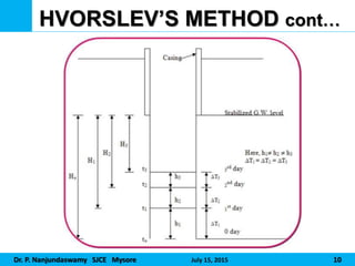
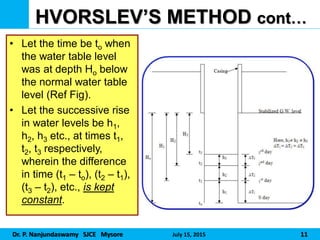
HVORSLEV’S METHOD cont…
• Let the time be to when
the water table level
was at depth Ho below
the normal water table
level (Ref Fig).
• Let the successive rise
in water levels be h1,
h2, h3 etc., at times t1,
t2, t3 respectively,
wherein the difference
in time (t1 – to), (t2 – t1),
(t3 – t2), etc., is kept
constant.
12.
Dr. P. NanjundaswamySJCE Mysore July 15, 2015 12
HVORSLEV’S METHOD cont…
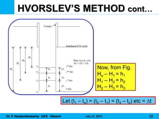
Let (t1 – to) = (t2 – t1) = (t3 – t2) etc = t
Now, from Fig.
Ho – H1 = h1
H1 – H2 = h2
H2 – H3 = h3
13.
Dr. P. NanjundaswamySJCE Mysore July 15, 2015 13
HVORSLEV’S METHOD cont…
2
1
2
1
h
h
h
Ho
2
1
2
2
2
h
h
h
H
3
2
2
3
3
h
h
h
H
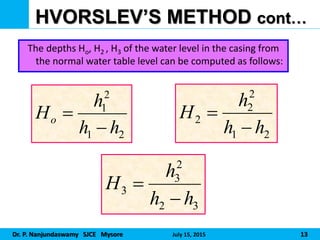
The depths Ho, H2 , H3 of the water level in the casing from
the normal water table level can be computed as follows:
14.
Dr. P. NanjundaswamySJCE Mysore July 15, 2015 14
HVORSLEV’S METHOD cont…
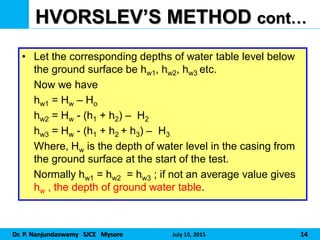
• Let the corresponding depths of water table level below
the ground surface be hw1, hw2, hw3 etc.
Now we have
hw1 = Hw – Ho
hw2 = Hw - (h1 + h2) – H2
hw3 = Hw - (h1 + h2 + h3) – H3
Where, Hw is the depth of water level in the casing from
the ground surface at the start of the test.
Normally hw1 = hw2 = hw3 ; if not an average value gives
hw , the depth of ground water table.
15.
Dr. P. NanjundaswamySJCE Mysore July 15, 2015 15
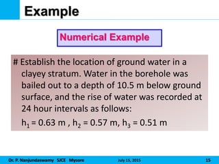
Example
Numerical Example
# Establish the location of ground water in a
clayey stratum. Water in the borehole was
bailed out to a depth of 10.5 m below ground
surface, and the rise of water was recorded at
24 hour intervals as follows:
h1 = 0.63 m , h2 = 0.57 m, h3 = 0.51 m
16.
Dr. P. NanjundaswamySJCE Mysore July 15, 2015 16
Example . . . .
m
h
h
h
Ho 615
.
6
057
63
.
0
63
.
0 2
2
1
2
1
m
h
h
h
H 415
.
5
057
63
.
0
57
.
0 2
2
1
2
2
2
m
h
h
h
H 335
.
4
51
.
0
57
.
0
51
.
0 2
3
2
2
3
3
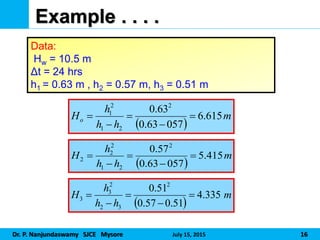
Data:
Hw = 10.5 m
Δt = 24 hrs
h1 = 0.63 m , h2 = 0.57 m, h3 = 0.51 m
17.
Dr. P. NanjundaswamySJCE Mysore July 15, 2015 17
Example . . . .
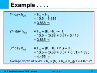
1st day hw1 = Hw – Ho
= 10.5 – 6.615
= 3.885 m
2nd day hw2 = Hw – (h1 +h2) – H2
= 10.5 – (0.63 + 0.57)- 5.415
= 3.885 m
3rd day hw3 = Hw – (h1 +h2 + h3) – H3
= 10.5 – (0.63 + 0.57 + 0.51)- 4.335
= 4.455 m
Average depth of G.W.L = hw = (hw1+ hw2+ hw3)/3 = 4.075 m
Dr. P. NanjundaswamySJCE Mysore July 15, 2015 19
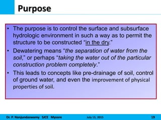
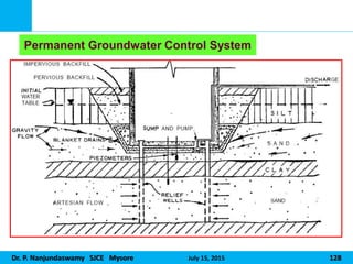
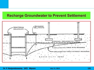
Purpose
• The purpose is to control the surface and subsurface
hydrologic environment in such a way as to permit the
structure to be constructed “in the dry.”
• Dewatering means “the separation of water from the
soil,” or perhaps “taking the water out of the particular
construction problem completely.”
• This leads to concepts like pre-drainage of soil, control
of ground water, and even the improvement of physical
properties of soil.
20.
Dr. P. NanjundaswamySJCE Mysore July 15, 2015 20
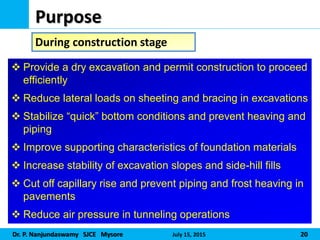
Purpose
During construction stage
Provide a dry excavation and permit construction to proceed
efficiently
Reduce lateral loads on sheeting and bracing in excavations
Stabilize “quick” bottom conditions and prevent heaving and
piping
Improve supporting characteristics of foundation materials
Increase stability of excavation slopes and side-hill fills
Cut off capillary rise and prevent piping and frost heaving in
pavements
Reduce air pressure in tunneling operations
21.
Dr. P. NanjundaswamySJCE Mysore July 15, 2015 21
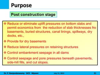
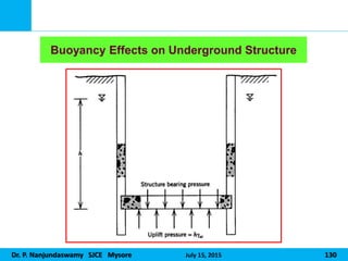
Purpose
Post construction stage
Reduce or eliminate uplift pressures on bottom slabs and
permit economics from the reduction of slab thicknesses fro
basements, buried structures, canal linings, spillways, dry
docks, etc.,
Provide for dry basements
Reduce lateral pressures on retaining structures
Control embankment seepage in all dams
Control seepage and pore pressures beneath pavements,
side-hill fills, and cut slopes.
Dr. P. NanjundaswamySJCE Mysore July 15, 2015 23
Methods
Exclusion Techniques
Dewatering Techniques
24.
Dr. P. NanjundaswamySJCE Mysore July 15, 2015 24
Methods . . . .
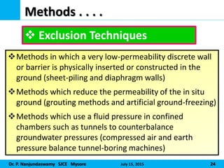
Exclusion Techniques
Methods in which a very low-permeability discrete wall
or barrier is physically inserted or constructed in the
ground (sheet-piling and diaphragm walls)
Methods which reduce the permeability of the in situ
ground (grouting methods and artificial ground-freezing)
Methods which use a fluid pressure in confined
chambers such as tunnels to counterbalance
groundwater pressures (compressed air and earth
pressure balance tunnel-boring machines)
25.
Dr. P. NanjundaswamySJCE Mysore July 15, 2015 25
Methods . . . .
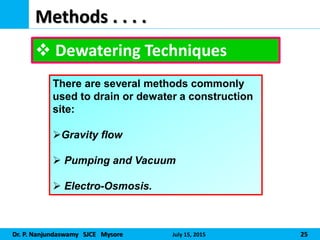
Dewatering Techniques
There are several methods commonly
used to drain or dewater a construction
site:
Gravity flow
Pumping and Vacuum
Electro-Osmosis.
Dr. P. NanjundaswamySJCE Mysore July 15, 2015 27
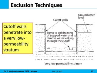
Exclusion Techniques
Cutoff walls
penetrate into
a very low-
permeability
stratum
28.
Dr. P. NanjundaswamySJCE Mysore July 15, 2015 28
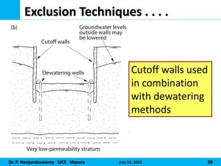
Exclusion Techniques . . . .
Cutoff walls used
in combination
with dewatering
methods
29.
Dr. P. NanjundaswamySJCE Mysore July 15, 2015 29
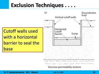
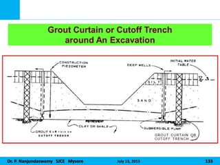
Exclusion Techniques . . . .
Cutoff walls used
with a horizontal
barrier to seal the
base
30.
Dr. P. NanjundaswamySJCE Mysore July 15, 2015 30
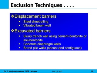
Exclusion Techniques . . . .
Displacement barriers
Steel sheet-piling
Vibrated beam wall
Excavated barriers
Slurry trench wall using cement-bentonite or
soil-bentonite
Concrete diaphragm walls
Bored pile walls (secant and contiguous)
31.
Dr. P. NanjundaswamySJCE Mysore July 15, 2015 31
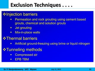
Exclusion Techniques . . . .
Injection barriers
Permeation and rock grouting using cement based
grouts, chemical and solution grouts
Jet grouting
Mix-in-place walls
Thermal barriers
Artificial ground-freezing using brine or liquid nitrogen
Tunneling methods
Compressed air
EPB TBM
Dr. P. NanjundaswamySJCE Mysore July 15, 2015 33
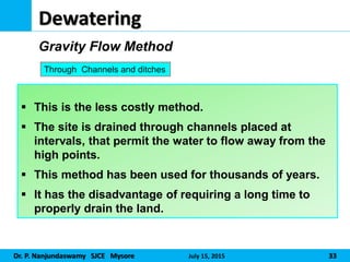
Dewatering
This is the less costly method.
The site is drained through channels placed at
intervals, that permit the water to flow away from the
high points.
This method has been used for thousands of years.
It has the disadvantage of requiring a long time to
properly drain the land.
Gravity Flow Method
Through Channels and ditches
34.
Dr. P. NanjundaswamySJCE Mysore July 15, 2015 34
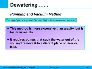
Dewatering . . . .
This method is more expensive than gravity, but is
faster in results.
It requires pumps that suck the water out of the
soil and remove it to a distant place or river or
lake.
Pumping and Vacuum Method
Through Open sumps and Ditches, Well points system and Vacuum
35.
Dr. P. NanjundaswamySJCE Mysore July 15, 2015 35
Dewatering . . . .
This method is most expensive
It is only effective method of
dewatering in deep clay soils.
Electro-Osmosis
Through use of Cathodes and Anodes with passage of Electrical current
36.
Dr. P. NanjundaswamySJCE Mysore July 15, 2015 36
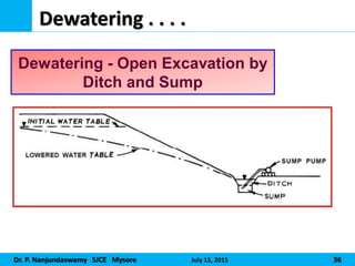
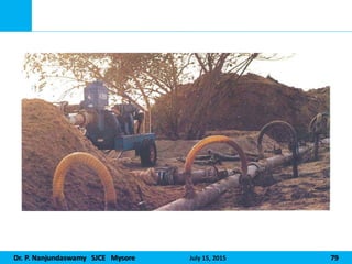
Dewatering . . . .
Dewatering - Open Excavation by
Ditch and Sump
37.
Dr. P. NanjundaswamySJCE Mysore July 15, 2015 37
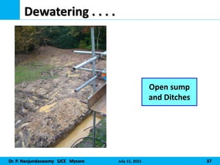
Dewatering . . . .
Open sump
and Ditches
38.
Dr. P. NanjundaswamySJCE Mysore July 15, 2015 38
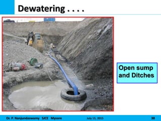
Dewatering . . . .
Open sump
and Ditches
39.
Dr. P. NanjundaswamySJCE Mysore July 15, 2015 39
Dewatering . . . .
CASE STUDY-1
No. 65, PUTANNA ROAD, GANDHIBAZAAR, BANGALORE
40.
Dr. P. NanjundaswamySJCE Mysore July 15, 2015 40
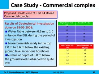
Case Study - Commercial complex
Results of Geotechnical Investigation
done on 18-05-2008:
Water Table between 0.6 m to 1.0
m below the EGL during the period of
investigation
Loose brownish sandy in the top
2.0 m to 3.6 m below the existing
ground level in various boreholes
N-value at depth of 3.0 m below
the ground level is observed to quite
low.
Proposed Construction of Stilt +4 storied
Commercial complex
Depth below NGL
(m)
Recorded N-value
1.5 4
2.0 7
2.5 10
3.0 12
4.5 30
Depth below NGL
(m)
Recommended SBC
(kN/m2)
1.5 60
2.0 100
2.5 130
3.0 160
4.5 300
41.
Dr. P. NanjundaswamySJCE Mysore July 15, 2015 41
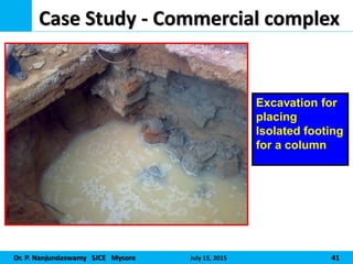
Case Study - Commercial complex
Excavation for
placing
Isolated footing
for a column
42.
Dr. P. NanjundaswamySJCE Mysore July 15, 2015 42
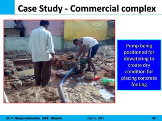
Case Study - Commercial complex
Pump being
positioned for
dewatering to
create dry
condition for
placing concrete
footing
43.
Dr. P. NanjundaswamySJCE Mysore July 15, 2015 43
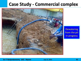
Case Study - Commercial complex
Dewatering
from the pit
in progress
44.
Dr. P. NanjundaswamySJCE Mysore July 15, 2015 44
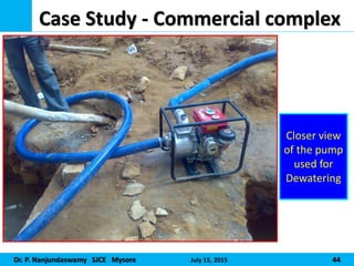
Case Study - Commercial complex
Closer view
of the pump
used for
Dewatering
45.
Dr. P. NanjundaswamySJCE Mysore July 15, 2015 45
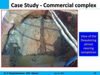
Case Study - Commercial complex
View of the
Dewatering
almost
nearing
completion
46.
Dr. P. NanjundaswamySJCE Mysore July 15, 2015 46
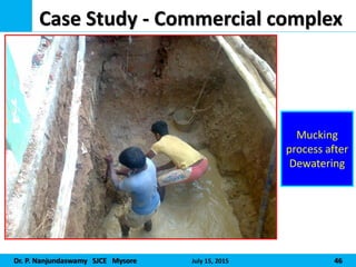
Case Study - Commercial complex
Mucking
process after
Dewatering
47.
Dr. P. NanjundaswamySJCE Mysore July 15, 2015 47
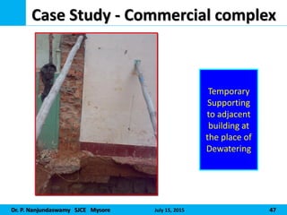
Case Study - Commercial complex
Temporary
Supporting
to adjacent
building at
the place of
Dewatering
48.
Dr. P. NanjundaswamySJCE Mysore July 15, 2015 48
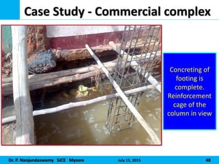
Case Study - Commercial complex
Concreting of
footing is
complete.
Reinforcement
cage of the
column in view
49.
Dr. P. NanjundaswamySJCE Mysore July 15, 2015 49
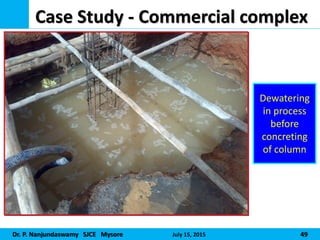
Case Study - Commercial complex
Dewatering
in process
before
concreting
of column
50.
Dr. P. NanjundaswamySJCE Mysore July 15, 2015 50
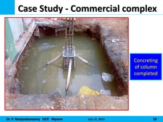
Case Study - Commercial complex
Concreting
of column
completed
51.
Dr. P. NanjundaswamySJCE Mysore July 15, 2015 51
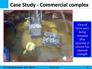
Case Study - Commercial complex
View of
Form work
being
removed
after
concrete of
column has
attained
strength
52.
Dr. P. NanjundaswamySJCE Mysore July 15, 2015 52
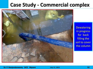
Case Study - Commercial complex
Dewatering
in progress
for back
filling the
soil to cover
the column
53.
Dr. P. NanjundaswamySJCE Mysore July 15, 2015 53
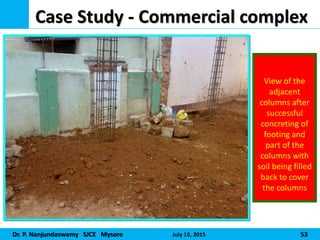
Case Study - Commercial complex
View of the
adjacent
columns after
successful
concreting of
footing and
part of the
columns with
soil being filled
back to cover
the columns
54.
Dr. P. NanjundaswamySJCE Mysore July 15, 2015 54
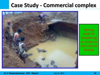
Case Study - Commercial complex
Getting
ready for
Dewatering
to construct
next column
footing
55.
Dr. P. NanjundaswamySJCE Mysore July 15, 2015 55
CASE STUDY-2
LIC OF INDIA, JEEVAN BHEEMA NAGAR,
BANGALORE
56.
Dr. P. NanjundaswamySJCE Mysore July 15, 2015 56
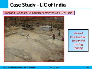
Case Study - LIC of India
View of
Construction
activity for
placing
footing
Proposed Residential Quarters for Employees of LIC of India
57.
Dr. P. NanjundaswamySJCE Mysore July 15, 2015 57
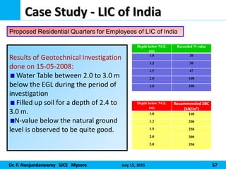
Case Study - LIC of India
Results of Geotechnical Investigation
done on 15-05-2008:
Water Table between 2.0 to 3.0 m
below the EGL during the period of
investigation
Filled up soil for a depth of 2.4 to
3.0 m.
N-value below the natural ground
level is observed to be quite good.
Proposed Residential Quarters for Employees of LIC of India
Depth below NGL
(m)
Recorded N-value
1.0 20
1.2 30
1.5 47
2.0 100
3.0 100
Depth below NGL
(m)
Recommended SBC
(kN/m2)
1.0 160
1.2 200
1.5 250
2.0 300
3.0 350
58.
Dr. P. NanjundaswamySJCE Mysore July 15, 2015 58
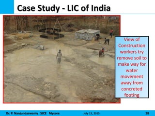
Case Study - LIC of India
View of
Construction
workers try
remove soil to
make way for
water
movement
away from
concreted
footing
59.
Dr. P. NanjundaswamySJCE Mysore July 15, 2015 59
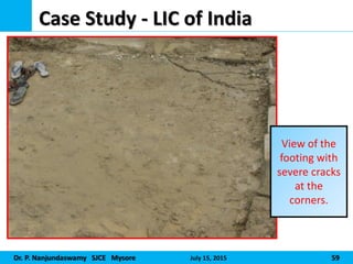
Case Study - LIC of India
View of the
footing with
severe cracks
at the
corners.
60.
Dr. P. NanjundaswamySJCE Mysore July 15, 2015 60
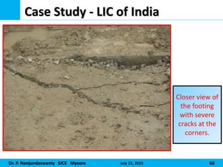
Case Study - LIC of India
Closer view of
the footing
with severe
cracks at the
corners.
61.
Dr. P. NanjundaswamySJCE Mysore July 15, 2015 61
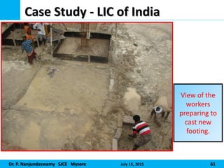
Case Study - LIC of India
View of the
workers
preparing to
cast new
footing.
62.
Dr. P. NanjundaswamySJCE Mysore July 15, 2015 62
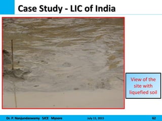
Case Study - LIC of India
View of the
site with
liquefied soil
63.
Dr. P. NanjundaswamySJCE Mysore July 15, 2015 63
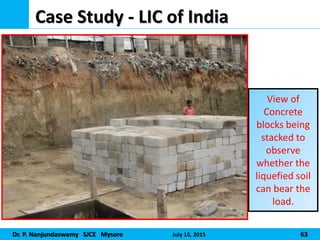
Case Study - LIC of India
View of
Concrete
blocks being
stacked to
observe
whether the
liquefied soil
can bear the
load.
64.
Dr. P. NanjundaswamySJCE Mysore July 15, 2015 64
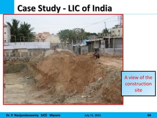
Case Study - LIC of India
A view of the
construction
site
65.
Dr. P. NanjundaswamySJCE Mysore July 15, 2015 65
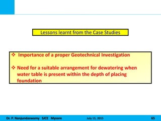
Lessons learnt from the Case Studies
Importance of a proper Geotechnical Investigation
Need for a suitable arrangement for dewatering when
water table is present within the depth of placing
foundation
66.
Dr. P. NanjundaswamySJCE Mysore July 15, 2015 66
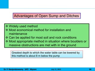
Advantages of Open Sump and Ditches
Widely used method
Most economical method for installation and
maintenance
Can be applied for most soil and rock conditions
Most appropriate method in situation where boulders or
massive obstructions are met with in the ground
Greatest depth to which the water table can be lowered by
this method is about 8 m below the pump
67.
Dr. P. NanjundaswamySJCE Mysore July 15, 2015 67
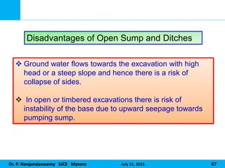
Disadvantages of Open Sump and Ditches
Ground water flows towards the excavation with high
head or a steep slope and hence there is a risk of
collapse of sides.
In open or timbered excavations there is risk of
instability of the base due to upward seepage towards
pumping sump.
68.
Dr. P. NanjundaswamySJCE Mysore July 15, 2015 68
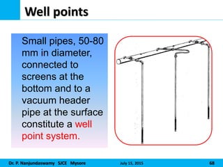
Well points
Small pipes, 50-80
mm in diameter,
connected to
screens at the
bottom and to a
vacuum header
pipe at the surface
constitute a well
point system.
69.
Dr. P. NanjundaswamySJCE Mysore July 15, 2015 69
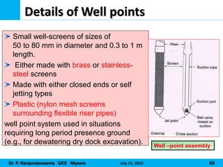
Details of Well points
Small well-screens of sizes of
50 to 80 mm in diameter and 0.3 to 1 m
length.
Either made with brass or stainless-
steel screens
Made with either closed ends or self
jetting types
Plastic (nylon mesh screens
surrounding flexible riser pipes)
well point system used in situations
requiring long period presence ground
(e.g., for dewatering dry dock excavation). Well –point assembly
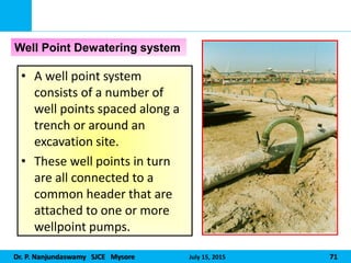
Dr. P. NanjundaswamySJCE Mysore July 15, 2015 71
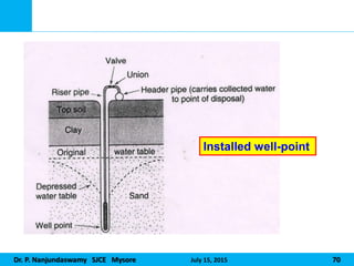
• A well point system
consists of a number of
well points spaced along a
trench or around an
excavation site.
• These well points in turn
are all connected to a
common header that are
attached to one or more
wellpoint pumps.
Well Point Dewatering system
72.
Dr. P. NanjundaswamySJCE Mysore July 15, 2015 72
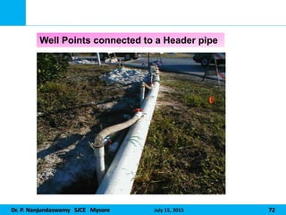
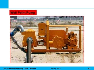
Well Points connected to a Header pipe
Dr. P. NanjundaswamySJCE Mysore July 15, 2015 80
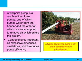
• A wellpoint pump is a
combination of two
pumps, one of which
pumps water from the
header and the other of
which is a vacuum pump
to remove air which enters
the system.
• Control of air is important,
as excessive air causes
cavitations, which reduces
pump efficiency.
A typical dewatering pump is a 6"
diesel powered vacuum
primed pump.
Dr. P. NanjundaswamySJCE Mysore July 15, 2015 82
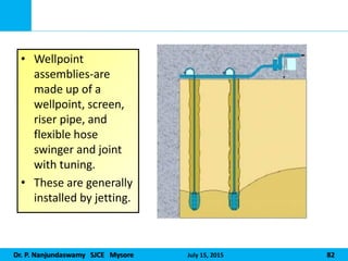
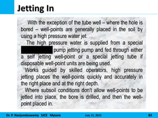
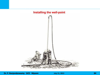
• Wellpoint
assemblies-are
made up of a
wellpoint, screen,
riser pipe, and
flexible hose
swinger and joint
with tuning.
• These are generally
installed by jetting.
Dr. P. NanjundaswamySJCE Mysore July 15, 2015 87
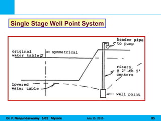
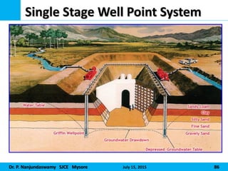
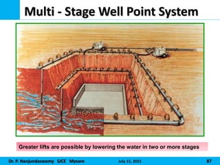
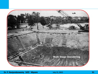
Multi - Stage Well Point System
Greater lifts are possible by lowering the water in two or more stages
88.
Dr. P. NanjundaswamySJCE Mysore July 15, 2015 88
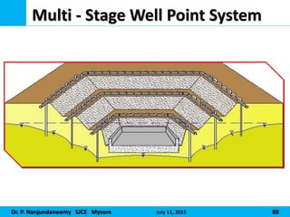
Multi - Stage Well Point System
89.
Dr. P. NanjundaswamySJCE Mysore July 15, 2015 89
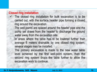
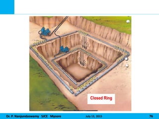
• Well point systems are frequently the most logical
and economical choice for dewatering construction
sites where the required lowering of ground water
level is approximately 6 m (20 feet)or less. However,
greater lifts are possible by lowering the water in two
or more stages.
• The 20-foot lift restriction results from the fact that
the water is lifted by difference between ambient air
pressure and the lowered pressure created by the
pump.
90.
Dr. P. NanjundaswamySJCE Mysore July 15, 2015 90
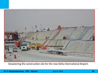
Dewatering the construction site for the new Doha International Airport.
Dr. P. NanjundaswamySJCE Mysore July 15, 2015 92
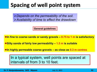
Spacing of well point system
General guidelines
Depends on the permeability of the soil.
Availability of time to effect the drawdown
In fine to coarse sands or sandy gravels – 0.75 to 1 m is satisfactory
Silty sands of fairly low permeability – 1.5 m is suitable
In highly permeable coarse gravels – as close as 0.3 m centres
In a typical system, well points are spaced at
intervals of from 3 to 10 feet.
93.
Dr. P. NanjundaswamySJCE Mysore July 15, 2015 93
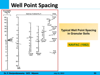
Well Point Spacing
Typical Well Point Spacing
in Granular Soils
NAVFAC (1982)
94.
Dr. P. NanjundaswamySJCE Mysore July 15, 2015 94
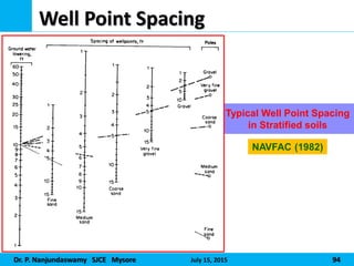
Well Point Spacing
Typical Well Point Spacing
in Stratified soils
NAVFAC (1982)
95.
Dr. P. NanjundaswamySJCE Mysore July 15, 2015 95
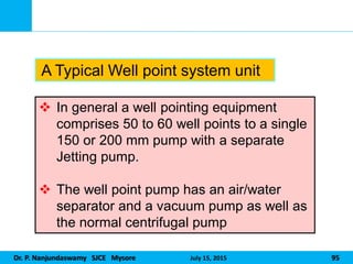
In general a well pointing equipment
comprises 50 to 60 well points to a single
150 or 200 mm pump with a separate
Jetting pump.
The well point pump has an air/water
separator and a vacuum pump as well as
the normal centrifugal pump
A Typical Well point system unit
96.
Dr. P. NanjundaswamySJCE Mysore July 15, 2015 96
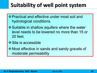
Suitability of well point system
Practical and effective under most soil and
hydrological conditions.
Suitable in shallow aquifers where the water
level needs to be lowered no more than 15 or
20 feet.
Site is accessible
Most effective in sands and sandy gravels of
moderate permeability
97.
Dr. P. NanjundaswamySJCE Mysore July 15, 2015 97
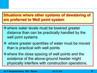
Situations where other systems of dewatering of
are preferred to Well point system
where water levels must be lowered greater
distance than can be practically handled by the
well point systems
where greater quantities of water must be moved
than is practical with well points
where the close spacing of well points and the
existence of the above-ground header might
physically interfere with construction operations.
98.
Dr. P. NanjundaswamySJCE Mysore July 15, 2015 98
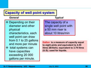
Capacity of well point system
Depending on their
diameter and other
physical
characteristics, each
well point can draw
from 0.1 to 25 gallons
and more per minute
total systems can
have capacities
exceeding 20 000
gallons per minute.
General Typical
The capacity of a
single well point with
a 50 mm riser is
about 10 litres/min
Gallon is a measure of capacity equal
to eight pints and equivalent to 4.55
litres (British); equivalent to 3.79 litres
(U.S); used for liquids.
99.
Dr. P. NanjundaswamySJCE Mysore July 15, 2015 99
The physical layout
Adjacent areas
Soil conditions
Permeability of the soil
The amount of water to be pumped
Depth to imperviousness
Stratification
Design considerations of well-point system
When designing a well point system, it is necessary
to give first consideration to the physical conditions
of the site to be dewatered
100.
Dr. P. NanjundaswamySJCE Mysore July 15, 2015 100
Advantages of well point system
Installation is very rapid
Requires reasonably simple and less costly
equipment
Water is filtered and carries little or no soil particles.
There is less danger of subsidence of the
surrounding ground than with open-sump pumping
101.
Dr. P. NanjundaswamySJCE Mysore July 15, 2015 101
Limitations of well point system
A lowering of about 6 m (20 ft) below pump level
is generally possible beyond which excessive air
shall be drawn into the system through the joints in
the pipes, valves, etc., resulting in the loss of
pumping efficiency
If the ground is consisting mainly of large gravel,
stiff clay or soil containing cobbles or boulders it is
not possible to install well points.
Dr. P. NanjundaswamySJCE Mysore July 15, 2015 103
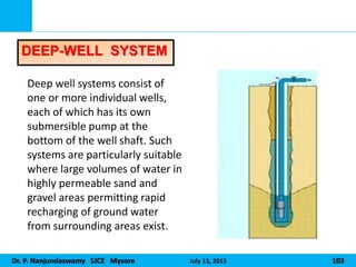
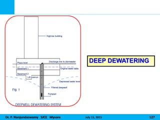
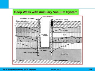
Deep well systems consist of
one or more individual wells,
each of which has its own
submersible pump at the
bottom of the well shaft. Such
systems are particularly suitable
where large volumes of water in
highly permeable sand and
gravel areas permitting rapid
recharging of ground water
from surrounding areas exist.
DEEP-WELL SYSTEM
104.
Dr. P. NanjundaswamySJCE Mysore July 15, 2015 104
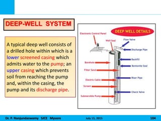
A typical deep well consists of
a drilled hole within which is a
lower screened casing which
admits water to the pump; an
upper casing which prevents
soil from reaching the pump
and, within the casing, the
pump and its discharge pipe.
DEEP-WELL SYSTEM
105.
Dr. P. NanjundaswamySJCE Mysore July 15, 2015 105
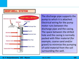
The discharge pipe supports the
pump to which it is attached.
Electrical wiring for the pump
motor runs between the
discharge pipe and the casing.
The space between the drilled
hole and the casing is normally
packed with filter material (for
example, coarse sand and/or
gravel) to minimize the pumping
of solid material from the soil
surrounding the well.
DEEP-WELL SYSTEM
106.
Dr. P. NanjundaswamySJCE Mysore July 15, 2015 106
Normally, individual wells are spaced at an
approximate distance of 50 feet apart.
However, depending upon soil conditions and the
dewatering plan the spacing may need to be just a
few feet apart.
Spacing of Deep well point system
107.
Dr. P. NanjundaswamySJCE Mysore July 15, 2015 107
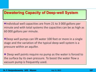
Individual well capacities are from 21 to 3 000 gallons per
minute and with total systems the capacities can be as high as
60 000 gallons per minute.
Deep well pumps can lift water 100 feet or more in a single
stage and the variation of the typical deep well system is a
pressure within an aquifer.
Deep well points require no pump as the water is forced to
the surface by its own pressure. To boost the water flow a
vacuum pump is frequently used.
Dewatering Capacity of Deep-well System
108.
Dr. P. NanjundaswamySJCE Mysore July 15, 2015 108
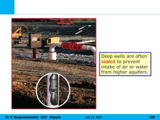
Deep wells are often
sealed to prevent
intake of air or water
from higher aquifers.
109.
Dr. P. NanjundaswamySJCE Mysore July 15, 2015 109
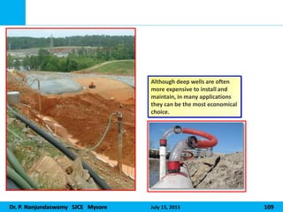
Although deep wells are often
more expensive to install and
maintain, in many applications
they can be the most economical
choice.
110.
Dr. P. NanjundaswamySJCE Mysore July 15, 2015 110
Design considerations of Deep well-point system
The soil investigation report
The grain size analysis and permeability tests
The hydrology of the area
The topography
The space limitations of the site and surrounding
structure.
The projected method of excavation and shoring
if any
The construction schedule
111.
Dr. P. NanjundaswamySJCE Mysore July 15, 2015 111
VACUUM DEWATERING
OR
EJECTOR/EDUCTOR
DEWATERING SYSTEMS
112.
Dr. P. NanjundaswamySJCE Mysore July 15, 2015 112
Ejector/Eductor dewatering systems are
employed to control pore pressures
To lower groundwater levels to provide
stable working conditions in excavations.
They are particularly suited to operating
in fine soil conditions.
SITUATIONS NEEDING EJECTOR/EDUCTOR
DEWATERING SYSTEMS
113.
Dr. P. NanjundaswamySJCE Mysore July 15, 2015 113
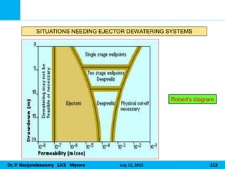
SITUATIONS NEEDING EJECTOR DEWATERING SYSTEMS
Robert’s diagram
114.
Dr. P. NanjundaswamySJCE Mysore July 15, 2015 114
Eductor systems are able to extract
groundwater and generate a high vacuum at
the base of wells up to 50 m deep and of as
little as 50 mm diameter.
Vacuum drainage can provide dramatic
improvement in the stability of silty fine sands
and laminated silts and clays by the control of
excess pore pressures.
Eductor wells have been successfully installed
in raking boreholes to dewater beneath
inaccessible areas such as railway lines and
canals.
115.
Dr. P. NanjundaswamySJCE Mysore July 15, 2015 115
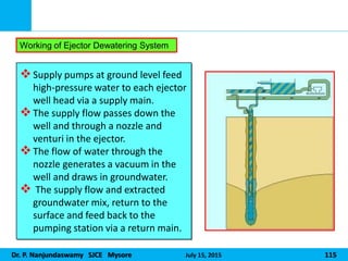
Supply pumps at ground level feed
high-pressure water to each ejector
well head via a supply main.
The supply flow passes down the
well and through a nozzle and
venturi in the ejector.
The flow of water through the
nozzle generates a vacuum in the
well and draws in groundwater.
The supply flow and extracted
groundwater mix, return to the
surface and feed back to the
pumping station via a return main.
Working of Ejector Dewatering System
116.
Dr. P. NanjundaswamySJCE Mysore July 15, 2015 116
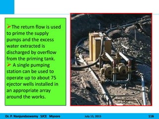
The return flow is used
to prime the supply
pumps and the excess
water extracted is
discharged by overflow
from the priming tank.
A single pumping
station can be used to
operate up to about 75
ejector wells installed in
an appropriate array
around the works.
Dr. P. NanjundaswamySJCE Mysore July 15, 2015 119
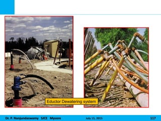
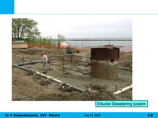
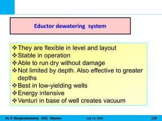
Eductor dewatering system
They are flexible in level and layout
Stable in operation
Able to run dry without damage
Not limited by depth. Also effective to greater
depths
Best in low-yielding wells
Energy intensive
Venturi in base of well creates vacuum
120.
Dr. P. NanjundaswamySJCE Mysore July 15, 2015 120
Only effective method of
dewatering in deep clay soils.
Electro-Osmosis
Through use of Cathodes and Anodes with passage of Electrical current
121.
Dr. P. NanjundaswamySJCE Mysore July 15, 2015 121
Electro-osmosis is the movement of water
(and whatever is contained in the water)
through a porous media by applying a
direct current (DC) field.
Definition
Dr. P. NanjundaswamySJCE Mysore July 15, 2015 123
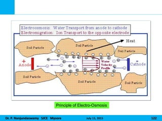
When electrodes are placed across a clay mass and
a direct current is applied, water in the clay pore
space is transported to the cathodically charged
electrode by electro-osmosis.
Electro-osmotic transport of water through a clay is
a result of diffuse double layer cations in the clay
pores being attracted to a negatively charged
electrode or cathode.
As these cations move toward the cathode, they
bring with them water molecules that clump around
the cations as a consequence of their dipolar nature.
Mechanism of Electro-osmosis
124.
Dr. P. NanjundaswamySJCE Mysore July 15, 2015 124
In addition, the frictional drag of these molecules as
they move through the clay pores help transport
additional water to the cathode.
The macroscopic effect is a reduction of water
content at the anode and an increase in water content
of the clay at the cathode.
In particular, free water appears at the interface
between the clay and the cathode surface.
This excess of free water at the cathode has
lubricating effects.
Mechanism of Electro-osmosis Cont’d
125.
Dr. P. NanjundaswamySJCE Mysore July 15, 2015 125
First, electro-osmosis provides uniform pore water movement in
most types of soil. Since the boundary layer movement towards the
cathode provides the motive force for the bulk pore water, the size
of the pore is not important.
Unlike hydraulic conductivity, electro-osmotic flow rate is NOT
sensitive to pore size. Electro-osmotic flow rate is primarily a
function of applied voltage. The electro-osmotic permeability for
any soil at 20oC is around 1 x 10⁻⁵ cm/s at 1 volt/cm.
The entire soil mass between the electrodes is basically treated
equally.
Effectiveness of Electro-osmosis
Electro-osmosis provides two benefits when properly applied
This is why electro-osmosis is so effective in clayey and heterogeneous soils.
126.
Dr. P. NanjundaswamySJCE Mysore July 15, 2015 126
Some Applications and Precautions in
Construction Dewatering and its control