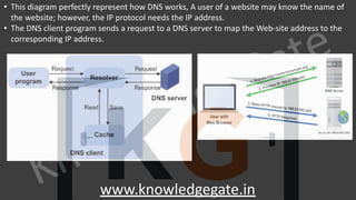
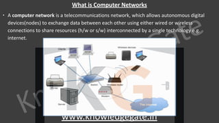
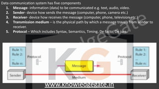
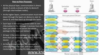
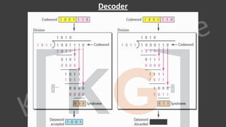
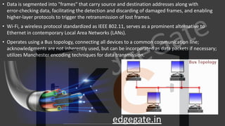
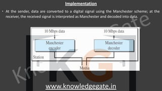
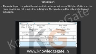
A computer network is a telecommunications network that enables digital devices to exchange data and resources, utilizing either wired or wireless connections. Key goals include facilitating communication, resource sharing, data access, cost efficiency, and enhancing reliability. The document also outlines various network topologies, models, and the layered architecture essential for effective data communication.


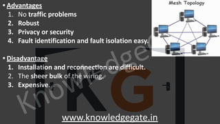


![KnowledgeGate
www.knowledgegate.in
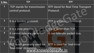
∙ Data
∙ It is a variable length field which contains the actual data, also called as a payload field.
∙ The length of this field lies in the range [46 bytes, 1500 bytes], i.e. in an Ethernet frame, minimum data has
to be 46 bytes and maximum data can be 1500 bytes.
∙ If it is less than 46 bytes, it needs to be padded with extra 0s.
∙ If more than 1500 bytes, it should be fragmented and encapsulated in more than one frame.](https://image.slidesharecdn.com/7-cnnotespptxwatermark1lyst8361-240317182742-af7f0545/85/Computer-network-notes-with-company-specific-questions-151-320.jpg)


![KnowledgeGate
www.knowledgegate.in
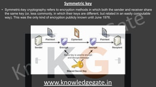
• Point to Note
• The length of IP header always lies in the range of [20 bytes, 60 bytes]
• The initial 5 rows of the IP header are always used. So, minimum length of IP header = 5 x 4 bytes =
20 bytes.
• The size of Options field can go up to 40 bytes. So, maximum length of IP header = 20 bytes + 40
bytes = 60 bytes.
• The range of header length field value is always [5, 15] as [20/4 = 5, 60/4 = 15]
• The range of header length is always [20, 60].](https://image.slidesharecdn.com/7-cnnotespptxwatermark1lyst8361-240317182742-af7f0545/85/Computer-network-notes-with-company-specific-questions-168-320.jpg)


![KnowledgeGate
www.knowledgegate.in
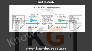
Class A
• In Class A NetID = 8 bits and HostID = 24.
• How to identify class A address
• First bit is reserved to 0 in binary notation
• Range of 1st
octet is [0, 127] in dotted decimal notation](https://image.slidesharecdn.com/7-cnnotespptxwatermark1lyst8361-240317182742-af7f0545/85/Computer-network-notes-with-company-specific-questions-225-320.jpg)
![KnowledgeGate
www.knowledgegate.in
• Total number of connections in class A is 231 (
2,14,74,83,648)
• There are 27
-2 = 126 networks in Class A network.
• In Class A, total network available are 2 less, because:
• IP Address 0.0.0.0 is reserved for broadcasting requirements
• IP Address 127.0.0.1 is reserved for loopback address / self-connectivity.
• The range of 1st
octet is [0, 127] but since two addresses are reserved it is: [1, 126].](https://image.slidesharecdn.com/7-cnnotespptxwatermark1lyst8361-240317182742-af7f0545/85/Computer-network-notes-with-company-specific-questions-226-320.jpg)

![KnowledgeGate
www.knowledgegate.in
Class B
• In Class B NetID = 16 bits and HostID = 16.
• How to identify class B address
• First two bits are reserved to 10 in binary notation
• Range of 1st
octet is [128, 191] in dotted decimal notation](https://image.slidesharecdn.com/7-cnnotespptxwatermark1lyst8361-240317182742-af7f0545/85/Computer-network-notes-with-company-specific-questions-228-320.jpg)

![KnowledgeGate
www.knowledgegate.in
Class C
• In Class C NetID = 24 bits and HostID = 8.
• How to identify class C address
• First three bits are reserved to 110 in binary notation
• Range of 1st
octet is [192, 223] in dotted decimal notation](https://image.slidesharecdn.com/7-cnnotespptxwatermark1lyst8361-240317182742-af7f0545/85/Computer-network-notes-with-company-specific-questions-230-320.jpg)

![KnowledgeGate
www.knowledgegate.in
Class D
• Class D is not divided into Network ID and Host ID.
• How to identify class D address
• First four bits are reserved to 1110 in binary notation
• Range of 1st
octet is [224, 239] in dotted decimal notation](https://image.slidesharecdn.com/7-cnnotespptxwatermark1lyst8361-240317182742-af7f0545/85/Computer-network-notes-with-company-specific-questions-232-320.jpg)

![KnowledgeGate
www.knowledgegate.in
Class E
• Class E is not divided into Network ID and Host ID.
• How to identify class E address
• First four bits are reserved to 1111 in binary notation
• Range of 1st
octet is [240, 255] in dotted decimal notation](https://image.slidesharecdn.com/7-cnnotespptxwatermark1lyst8361-240317182742-af7f0545/85/Computer-network-notes-with-company-specific-questions-234-320.jpg)


![KnowledgeGate
www.knowledgegate.in
Q Consider the network having IP Address 200.1.2.0. Divide this network into two subnets.
1st Subnet
∙ IP Address of the subnet / Subnet id = 200.1.2.0
∙ Direct Broadcast Address = 200.1.2.01111111 = 200.1.2.127
∙ Total number of IP Addresses = 27
= 128
∙ Range of IP Addresses = [200.1.2.0, 200.1.2.127]
∙ Total number of hosts that can be configured = 128 – 2 = 126
∙ Range of Allocated IP Addresses = [200.1.2.1, 200.1.2.126]
2nd Subnet
∙ IP Address of the subnet / Subnet id = 200.1.2.128
∙ Direct Broadcast Address = 200.1.2.11111111 = 200.1.2.255
∙ Total number of IP Addresses = 27
= 128
∙ Range of IP Addresses = [200.1.2.128, 200.1.2.255]
∙ Total number of hosts that can be configured = 128 – 2 = 126
∙ Range of Allocated IP Addresses = [200.1.2.129, 200.1.2.254]](https://image.slidesharecdn.com/7-cnnotespptxwatermark1lyst8361-240317182742-af7f0545/85/Computer-network-notes-with-company-specific-questions-251-320.jpg)
![KnowledgeGate
www.knowledgegate.in
Q Consider we have a big single network having IP Address 200.1.2.0. We want to do subnetting
and divide this network into 4 subnets.
1st Subnet
∙ IP Address of the subnet / Subnet id = 200.1.2.0
∙ Direct Broadcast Address = 200.1.2.00111111 = 200.1.2.63
∙ Total number of IP Addresses = 26
= 64
∙ Range of IP Addresses = [200.1.2.0, 200.1.2.63]
∙ Total number of hosts that can be configured = 64 – 2 = 62
∙ Range of Allocated IP Addresses = [200.1.2.1, 200.1.2.62]
2nd Subnet
∙ IP Address of the subnet / Subnet id = 200.1.2.64
∙ Direct Broadcast Address = 200.1.2.01111111 = 200.1.2.127
∙ Total number of IP Addresses = 26
= 64
∙ Range of IP Addresses = [200.1.2.64, 200.1.2.127]
∙ Total number of hosts that can be configured = 64 – 2 = 62
∙ Range of Allocated IP Addresses = [200.1.2.65, 200.1.2.126]
3rd Subnet
∙ IP Address of the subnet / Subnet id = 200.1.2.128
∙ Direct Broadcast Address = 200.1.2.10111111 = 200.1.2.191
∙ Total number of IP Addresses = 26
= 64
∙ Range of IP Addresses = [200.1.2.128, 200.1.2.191]
∙ Total number of hosts that can be configured = 64 – 2 = 62
∙ Range of Allocated IP Addresses = [200.1.2.129, 200.1.2.190]
4th Subnet
∙ IP Address of the subnet / Subnet id = 200.1.2.192
∙ Direct Broadcast Address = 200.1.2.11111111 = 200.1.2.255
∙ Total number of IP Addresses = 26
= 64
∙ Range of IP Addresses = [200.1.2.192, 200.1.2.255]
∙ Total number of hosts that can be configured = 64 – 2 = 62
∙ Range of Allocated IP Addresses = [200.1.2.193, 200.1.2.254]](https://image.slidesharecdn.com/7-cnnotespptxwatermark1lyst8361-240317182742-af7f0545/85/Computer-network-notes-with-company-specific-questions-253-320.jpg)


![KnowledgeGate
www.knowledgegate.in
Q Consider we have a big single network having IP Address 200.1.2.0. We want to do subnetting and divide this
network into 3 subnets, such that first contains 126 hosts, and other two contains 62 hosts each?
1st Subnet
∙ IP Address of the subnet / Subnet id = 200.1.2.0
∙ Direct Broadcast Address = 200.1.2.01111111 = 200.1.2.127
∙ Total number of IP Addresses = 27
= 128
∙ Range of IP Addresses = [200.1.2.0, 200.1.2.127]
∙ Total number of hosts that can be configured = 128 – 2 = 126
∙ Range of Allocated IP Addresses = [200.1.2.1, 200.1.2.126]
2nd Subnet
∙ IP Address of the subnet / Subnet id = 200.1.2.128
∙ Direct Broadcast Address = 200.1.2.101111111 = 200.1.2.191
∙ Total number of IP Addresses = 26
= 64
∙ Range of IP Addresses = [200.1.2.128, 200.1.2.191]
∙ Total number of hosts that can be configured = 64 – 2 = 62
∙ Range of Allocated IP Addresses = [200.1.2.129, 200.1.2.190]
3rd Subnet
∙ IP Address of the subnet / Subnet id = 200.1.2.192
∙ Direct Broadcast Address = 200.1.2.111111111 = 200.1.2.255
∙ Total number of IP Addresses = 26
= 64
∙ Range of IP Addresses = [200.1.2.192, 200.1.2.255]
∙ Total number of hosts that can be configured = 64 – 2 = 62
∙ Range of Allocated IP Addresses = [200.1.2.193, 200.1.2.254]](https://image.slidesharecdn.com/7-cnnotespptxwatermark1lyst8361-240317182742-af7f0545/85/Computer-network-notes-with-company-specific-questions-256-320.jpg)
![KnowledgeGate
www.knowledgegate.in
Q Consider we have a big single network having IP Address 200.1.2.0. We want to do subnetting and divide this
network into 3 subnets, such that first contains 126 hosts, and other two contains 62 hosts each?
1st Subnet
∙ IP Address of the subnet / Subnet id = 200.1.2.0
∙ Direct Broadcast Address = 200.1.2.00111111 = 200.1.2.63
∙ Total number of IP Addresses = 26
= 64
∙ Range of IP Addresses = [200.1.2.0, 200.1.2.63]
∙ Total number of hosts that can be configured = 64 – 2 = 62
∙ Range of Allocated IP Addresses = [200.1.2.1, 200.1.2.62]
2nd Subnet
∙ IP Address of the subnet / Subnet id = 200.1.2.64
∙ Direct Broadcast Address = 200.1.2.011111111 = 200.1.2.127
∙ Total number of IP Addresses = 26
= 64
∙ Range of IP Addresses = [200.1.2.64, 200.1.2.127]
∙ Total number of hosts that can be configured = 64 – 2 = 62
∙ Range of Allocated IP Addresses = [200.1.2.65, 200.1.2.126]
3rd Subnet
∙ IP Address of the subnet / Subnet id = 200.1.2.128
∙ Direct Broadcast Address = 200.1.2.111111111 = 200.1.2.255
∙ Total number of IP Addresses = 27
= 128
∙ Range of IP Addresses = [200.1.2.128, 200.1.2.255]
∙ Total number of hosts that can be configured = 128 – 2 = 126
∙ Range of Allocated IP Addresses = [200.1.2.129, 200.1.2.254]](https://image.slidesharecdn.com/7-cnnotespptxwatermark1lyst8361-240317182742-af7f0545/85/Computer-network-notes-with-company-specific-questions-257-320.jpg)


![KnowledgeGate
www.knowledgegate.in
Address Mask
∙ The address mask is a 32-bit number in which the n leftmost bits are set to 1s
and the rest of the bits (32 − n) are set to 0s.
∙ It is another way to find the first and last addresses in the block.
∙ Using the three bit-wise operations NOT, AND, and OR a computer can find:
1. The number of addresses in the block N = NOT (mask) + 1.
2. The first address in the block = (Any address in the block) AND (mask).
3. The last address in the block = (Any address in the block) OR [(NOT (mask)].](https://image.slidesharecdn.com/7-cnnotespptxwatermark1lyst8361-240317182742-af7f0545/85/Computer-network-notes-with-company-specific-questions-267-320.jpg)


![KnowledgeGate
www.knowledgegate.in
Q Consider the network having IP Address 40.30.20.10/25 Divide this network into two subnets.
1st Subnet
∙ 40.30.20.00001010
∙ Total number of IP Addresses = 26
= 64
∙ First Address of the Subnet = 40.30.20.00000000
∙ Last Address of the Subnet = 40.30.20.00111111
∙ Range of IP Addresses = [40.30.20.0, 40.30.20.63]
∙ Total number of hosts that can be configured = 64 – 2 = 62
∙ Range of Allocated IP Addresses = [40.30.20.1, 40.30.20.62]
∙ CIRD Representation 40.30.20. __/26
40.30.20.00001010
0,1,2,3,4,5,-----------------------------------------------------------,63
2st Subnet
∙ 40.30.20.01001010
∙ Total number of IP Addresses = 26
= 64
∙ First Address of the Subnet = 40.30.20.01000000
∙ Last Address of the Subnet = 40.30.20.01111111
∙ Range of IP Addresses = [40.30.20.64, 40.30.20.127]
∙ Total number of hosts that can be configured = 64 – 2 = 62
∙ Range of Allocated IP Addresses = [40.30.20.65, 40.30.20.126]
∙ CIRD Representation 40.30.20. __/26
64,65,66,67,-------------------------------------------------------,127](https://image.slidesharecdn.com/7-cnnotespptxwatermark1lyst8361-240317182742-af7f0545/85/Computer-network-notes-with-company-specific-questions-270-320.jpg)

![KnowledgeGate
www.knowledgegate.in
Q Consider we have a big single network having IP Address 200.1.2.0/24. We want to do
subnetting and divide this network into 4 subnets.
1st Subnet
∙ IP Address of the subnet / Subnet id = 200.1.2.0
∙ Direct Broadcast Address = 200.1.2.00111111 = 200.1.2.63
∙ Total number of IP Addresses = 26
= 64
∙ Range of IP Addresses = [200.1.2.0, 200.1.2.63]
∙ Total number of hosts that can be configured = 64 – 2 = 62
∙ Range of Allocated IP Addresses = [200.1.2.1, 200.1.2.62]
2nd Subnet
∙ IP Address of the subnet / Subnet id = 200.1.2.64
∙ Direct Broadcast Address = 200.1.2.01111111 = 200.1.2.127
∙ Total number of IP Addresses = 26
= 64
∙ Range of IP Addresses = [200.1.2.64, 200.1.2.127]
∙ Total number of hosts that can be configured = 64 – 2 = 62
∙ Range of Allocated IP Addresses = [200.1.2.65, 200.1.2.126]
3rd Subnet
∙ IP Address of the subnet / Subnet id = 200.1.2.128
∙ Direct Broadcast Address = 200.1.2.10111111 = 200.1.2.191
∙ Total number of IP Addresses = 26
= 64
∙ Range of IP Addresses = [200.1.2.128, 200.1.2.191]
∙ Total number of hosts that can be configured = 64 – 2 = 62
∙ Range of Allocated IP Addresses = [200.1.2.129, 200.1.2.190]
4th Subnet
∙ IP Address of the subnet / Subnet id = 200.1.2.192
∙ Direct Broadcast Address = 200.1.2.11111111 = 200.1.2.255
∙ Total number of IP Addresses = 26
= 64
∙ Range of IP Addresses = [200.1.2.192, 200.1.2.255]
∙ Total number of hosts that can be configured = 64 – 2 = 62
∙ Range of Allocated IP Addresses = [200.1.2.193, 200.1.2.254]](https://image.slidesharecdn.com/7-cnnotespptxwatermark1lyst8361-240317182742-af7f0545/85/Computer-network-notes-with-company-specific-questions-272-320.jpg)

![KnowledgeGate
www.knowledgegate.in
Q Consider we have a big single network having IP Address 200.1.2.0/24. We want to do subnetting and divide this
network into 3 subnets, such that first contains 126 hosts, and other two contains 62 hosts each?
1st Subnet
∙ IP Address of the subnet / Subnet id = 200.1.2.0
∙ Direct Broadcast Address = 200.1.2.01111111 = 200.1.2.127
∙ Total number of IP Addresses = 27
= 128
∙ Range of IP Addresses = [200.1.2.0, 200.1.2.127]
∙ Total number of hosts that can be configured = 128 – 2 = 126
∙ Range of Allocated IP Addresses = [200.1.2.1, 200.1.2.126]
2nd Subnet
∙ IP Address of the subnet / Subnet id = 200.1.2.128
∙ Direct Broadcast Address = 200.1.2.101111111 = 200.1.2.191
∙ Total number of IP Addresses = 26
= 64
∙ Range of IP Addresses = [200.1.2.128, 200.1.2.191]
∙ Total number of hosts that can be configured = 64 – 2 = 62
∙ Range of Allocated IP Addresses = [200.1.2.129, 200.1.2.190]
3rd Subnet
∙ IP Address of the subnet / Subnet id = 200.1.2.192
∙ Direct Broadcast Address = 200.1.2.111111111 = 200.1.2.255
∙ Total number of IP Addresses = 26
= 64
∙ Range of IP Addresses = [200.1.2.192, 200.1.2.255]
∙ Total number of hosts that can be configured = 64 – 2 = 62
∙ Range of Allocated IP Addresses = [200.1.2.193, 200.1.2.254]](https://image.slidesharecdn.com/7-cnnotespptxwatermark1lyst8361-240317182742-af7f0545/85/Computer-network-notes-with-company-specific-questions-274-320.jpg)
![KnowledgeGate
www.knowledgegate.in
Q Consider we have a big single network having IP Address 200.1.2.0/24. We want to do subnetting and divide this
network into 3 subnets, such that first contains 126 hosts, and other two contains 62 hosts each?
1st Subnet
∙ IP Address of the subnet / Subnet id = 200.1.2.0
∙ Direct Broadcast Address = 200.1.2.00111111 = 200.1.2.63
∙ Total number of IP Addresses = 26
= 64
∙ Range of IP Addresses = [200.1.2.0, 200.1.2.63]
∙ Total number of hosts that can be configured = 64 – 2 = 62
∙ Range of Allocated IP Addresses = [200.1.2.1, 200.1.2.62]
2nd Subnet
∙ IP Address of the subnet / Subnet id = 200.1.2.64
∙ Direct Broadcast Address = 200.1.2.011111111 = 200.1.2.127
∙ Total number of IP Addresses = 26
= 64
∙ Range of IP Addresses = [200.1.2.64, 200.1.2.127]
∙ Total number of hosts that can be configured = 64 – 2 = 62
∙ Range of Allocated IP Addresses = [200.1.2.65, 200.1.2.126]
3rd Subnet
∙ IP Address of the subnet / Subnet id = 200.1.2.128
∙ Direct Broadcast Address = 200.1.2.111111111 = 200.1.2.255
∙ Total number of IP Addresses = 27
= 128
∙ Range of IP Addresses = [200.1.2.128, 200.1.2.255]
∙ Total number of hosts that can be configured = 128 – 2 = 126
∙ Range of Allocated IP Addresses = [200.1.2.129, 200.1.2.254]](https://image.slidesharecdn.com/7-cnnotespptxwatermark1lyst8361-240317182742-af7f0545/85/Computer-network-notes-with-company-specific-questions-275-320.jpg)


![KnowledgeGate
www.knowledgegate.in
Sequence number
• TCP is a stream transport protocol. To ensure connectivity, each byte to be transmitted is numbered. Sequence number is
32-bit field defines the number assigned to the first byte of data contained in this segment. So, maximum number of possible
sequence numbers = 232
. These sequence numbers lie in the range [0, 232
– 1].
• During connection establishment, each party uses a random number generator to create an initial sequence number (ISN),
which is usually different in each direction. Sequence number should be started at random, to remove duplication problem.
The sequence number of any other segment is the sequence number of the previous segment plus the number of bytes (real
or imaginary) carried by the previous segment.](https://image.slidesharecdn.com/7-cnnotespptxwatermark1lyst8361-240317182742-af7f0545/85/Computer-network-notes-with-company-specific-questions-312-320.jpg)