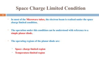
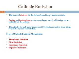
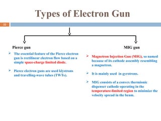
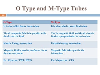
The document outlines a comprehensive examination related to a PhD program in Electronics & Communication Engineering, detailing coursework and content including advanced antenna engineering, RF IC design, satellite communication, and computational electromagnetics. It discusses critical concepts like space charge, cathode emission types, and various high power microwave sources such as relativistic klystrons and magnetrons. Additionally, it includes references and technical descriptions relevant to the topics covered.
![Cont….
(1)
Where, = Beam propagation constant
= Plasma propagation constant
The dispersion relation has been obtained with reference to a beam of infinite cross-section. There are two
space-charge waves corresponding to the plus and minus signs, respectively.
Fig.1.Dispersion diagram for space-charge waves[6]
0
p
e p
v
e
p
12](https://image.slidesharecdn.com/comprehensiveexamination-241203062542-a24ff4a3/85/Comprehensive-Examination-ppt-based-on-comprehensive-viva-for-phd-exam-12-320.jpg)
![Cont…
Fig.4. Potential distribution in the anode cathode region[6]
14](https://image.slidesharecdn.com/comprehensiveexamination-241203062542-a24ff4a3/85/Comprehensive-Examination-ppt-based-on-comprehensive-viva-for-phd-exam-14-320.jpg)
![The Child–Langmuir relation under the space-
charge-limited condition of emission
A Child –Langmuir relation states that for a planar diode how the anode
current depends on the anode potential as well as on the separation between
the cathode and the anode[2].
The Child –Langmuir relation is also known as the 3/2 power law.
[2]
Where,
= distance between the planar anode and cathode
= anode current
= anode potential
= current density
3/2
0 0
0 2
4 2
9
I V
J
A d
0
I
0
V
d
15
J](https://image.slidesharecdn.com/comprehensiveexamination-241203062542-a24ff4a3/85/Comprehensive-Examination-ppt-based-on-comprehensive-viva-for-phd-exam-15-320.jpg)
![Thermionic Emission
The emission of electrons resulting from the heating of a surface is referred to as thermionic
emission.
The intensity of thermionic emission depends on the metal used for the emission as well as
the temperature of the metal.
Thermionic emission cathodes are used in linear beam tubes.
Fig.5.Energy level near the surface of a metal[2]
17](https://image.slidesharecdn.com/comprehensiveexamination-241203062542-a24ff4a3/85/Comprehensive-Examination-ppt-based-on-comprehensive-viva-for-phd-exam-17-320.jpg)
![Field Emission
Field emission is formed by using a very high electric field.
This emission is also referred to as cold cathode emission.
The emission is a field emission if the energy responsible for it is in the form of
electric energy.
Fig.6. Energy profile with a very strong electric field[2]
18](https://image.slidesharecdn.com/comprehensiveexamination-241203062542-a24ff4a3/85/Comprehensive-Examination-ppt-based-on-comprehensive-viva-for-phd-exam-18-320.jpg)
![Secondary Emission
When electrons bombard a surface, they may cause other electrons to be emitted from
that surface. The bombarding electrons are called primary electrons and the emitted
electrons are called secondary electrons.
Secondary emission is often used in conventional crossed-field microwave tubes to
decrease (or eliminate) the required heater power.
Fig.7. Secondary emission[2]
19](https://image.slidesharecdn.com/comprehensiveexamination-241203062542-a24ff4a3/85/Comprehensive-Examination-ppt-based-on-comprehensive-viva-for-phd-exam-19-320.jpg)
![Explosive Emission
The emission of electrons from a plasma created on the cathode surface by the application of a
strong electric field.
Field-enhancement usually at the metallic surfaces tips of microprotrusions causes explosive
vaporization. This causes very high density metal plasma to form near the cathode surface.
For large pulse power system (explosive electron emission) EEE methods are used to generate Giga-
watt power pulsed high current electron beams.
Fig.8. Microscopic view of the local electric field enhancement at the tip of a whisker-like protrusion on
the cathode surface[10]
20](https://image.slidesharecdn.com/comprehensiveexamination-241203062542-a24ff4a3/85/Comprehensive-Examination-ppt-based-on-comprehensive-viva-for-phd-exam-20-320.jpg)
![Electron Gun
It is used to generate, form and shape the electron beam prior to its use.
The electron gun emits electrons and forms them into a beam by the help of a
heater, cathode, grid, pre-accelerating, accelerating and focusing anode.
The two principal parameters of electron gun design are perveance and
convergence ratio.
Fig.8. Electron Gun
Fig.9. Eletron gun[5]
21](https://image.slidesharecdn.com/comprehensiveexamination-241203062542-a24ff4a3/85/Comprehensive-Examination-ppt-based-on-comprehensive-viva-for-phd-exam-21-320.jpg)
![Relativistic Klystron
It is a relativistic version of conventional Klystron.
It is widely used as high energy drivers for free electron lasers, directed energy weapons,
colliders and accelerators.
Features:
Linear Beam Device
Magnetic Field- Axial
O-Type Devices
Velocity Modulation for Electron Bunching
Fig.10.Schematic of relativistic klystron[7]
26](https://image.slidesharecdn.com/comprehensiveexamination-241203062542-a24ff4a3/85/Comprehensive-Examination-ppt-based-on-comprehensive-viva-for-phd-exam-26-320.jpg)
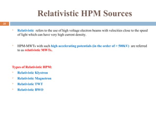
![Relativistic Backward Wave
Oscillator
It is the relativistic version, an O-type and Cherenkov radiation based device, operating at higher current and voltage.
It is widely used to the high power microwave generation for the military applications.
The reflector plays a vital role in the RBWO operation as it transforms the backward reflected waves into the forward propagating waves.
The SWS structure is used to decrease the phase velocity of the RF wave in such a manner that the electron beam gets synchronized with
it.
Fig.11.Schematic of RBWO[7]
27](https://image.slidesharecdn.com/comprehensiveexamination-241203062542-a24ff4a3/85/Comprehensive-Examination-ppt-based-on-comprehensive-viva-for-phd-exam-27-320.jpg)
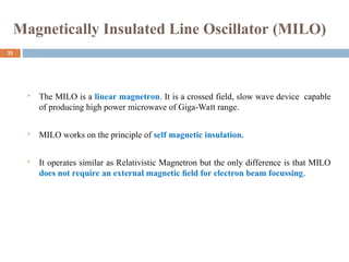
![Relativistic Magnetron
The relativistic magnetron is the relativistic version of the conventional magnetron
which is driven by DC pulsed power and cold cathode technology, and
fundamental difference is that it uses high voltage and current.
The suitable operating voltages and the fields can be determined from the
mathematical relations known as Buneman-Hartree condition and the Hull cutoff
condition.
Fig.12. Schematic of Relativistic magnetron[7]
28](https://image.slidesharecdn.com/comprehensiveexamination-241203062542-a24ff4a3/85/Comprehensive-Examination-ppt-based-on-comprehensive-viva-for-phd-exam-28-320.jpg)
![Cont…
The electron just gazes the anode as indicated in Figure (a), which is the Hull Cutoff condition.
The electron strikes the anode as indicated in Figure (b).
The electron returns to the cathode Figure (c).
Fig.13.Electron trajectories for various anode potential[2]
29
a
V
H
V
=Anode Voltage
= Hull cutoff voltage](https://image.slidesharecdn.com/comprehensiveexamination-241203062542-a24ff4a3/85/Comprehensive-Examination-ppt-based-on-comprehensive-viva-for-phd-exam-29-320.jpg)
![Cont…
MILO consists of a coaxial loaded metal discs working as the slow wave structure
(SWS), explosive emission cathode, metal discs acting as a filter cum choke cavity,
extractor cavity, stub and the collector.
Features of MILO:
Self-Magnetic field generation
M-Type Microwave Tube (crossed-field device)
Slow-wave Device Fig.14. Schematic of MILO[8]
π - mode of operation
32](https://image.slidesharecdn.com/comprehensiveexamination-241203062542-a24ff4a3/85/Comprehensive-Examination-ppt-based-on-comprehensive-viva-for-phd-exam-32-320.jpg)
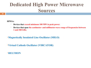
![Virtual Cathode Oscillator (VIRCATOR)
It is a high power microwave oscillator, which are essentially based on bremsstrahlung
radiation in the magnetic field.
Vircator differs from the rest HPM Devices in the way that microwave radiation is not
generated from the interaction of an electron beam and a cavity.
Vircator depends on the phenomena of formation of virtual cathode.
Features:
No external magnetic is required,
Simple design
Frequency tunability.
Low efficiency.
Fig.15.Basic Vircator Geometry[7]
Insulator Anode
Virtual Cathode
Window
Cathode
33](https://image.slidesharecdn.com/comprehensiveexamination-241203062542-a24ff4a3/85/Comprehensive-Examination-ppt-based-on-comprehensive-viva-for-phd-exam-33-320.jpg)
![Cont…
When a virtual cathode is formed , two things happen:
The location of the virtual cathode oscillates back and forth at roughly the beam plasma
frequency.
The oscillation of electrons between cathode and virtual cathode are known as reflexing.
Fig.16. Basic vircator geometries: (a) axial extraction and (b) side extraction.[1]
34](https://image.slidesharecdn.com/comprehensiveexamination-241203062542-a24ff4a3/85/Comprehensive-Examination-ppt-based-on-comprehensive-viva-for-phd-exam-34-320.jpg)
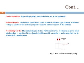
![Cont…
Elements of Reltron
Power Modulator
Electron Source
Modulating Cavity
Post acceleration Gap
Extraction Cavity
Beam Dump
Fig.17. Schematic of Reltron[7]
37](https://image.slidesharecdn.com/comprehensiveexamination-241203062542-a24ff4a3/85/Comprehensive-Examination-ppt-based-on-comprehensive-viva-for-phd-exam-37-320.jpg)
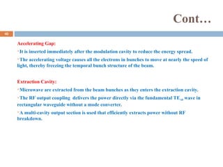
![Cont…
Fig.19. The electric field amplitudes of the three resonant mode of the beam modulation structure[7]
The modulating cavity has three resonant modes that can exist inside the cavity, i.e. 0, π/2
and π modes.
The coupling cavity is adjusted with the main cavity in such a way that modulating cavity
resonate at desired π/2 mode and maximum RF energy transfer occurs through this mode.
39](https://image.slidesharecdn.com/comprehensiveexamination-241203062542-a24ff4a3/85/Comprehensive-Examination-ppt-based-on-comprehensive-viva-for-phd-exam-39-320.jpg)
![Reference
[1]J. Benford, J. A. Swegle and E. Schamilogdu, “High Power Microwave”, 2nd
Edition , Taylor & Francis,
2007.
[2] Gilmour A S 2011 Klystrons, Traveling Wave Tubes, Magnetrons Crossed-Field Amplifiers, and
Gyrotrons (Boston: Artech House)
[3] Collin R E 1992 Foundations for Microwave Engineering 2nd edn (New York: Wiley-IEEE Press)
[4] Basu B N 1996 Electromagnetic Theory and Applications in Beam-wave Electronics (Singapore: World
Scientific)
[5]Roy, Amitava Saxena, A.K., & Ray, A.K. (Eds.). (2010). Electronic emission and electron guns. India:
Bhabha Atomic Research Centre.
[6] Vishal Keshari, Basu B N High Power Microwave Tubes, Volume 1: Basics and Trends
[7] Vishal Keshari, Basu B N High Power Microwave Tubes, Volume 2: Basics and Trends
[8] Mahto,M and jain, P.K.,2017, “Analysis, Design and Simulation of the HPM source-Reltron,” Ph.D.
Thesis, IIT BHU, Varanasi, 2017.
[9] Gargi Dixit, Arjun Kumar, and P. K. Jain, “Design analysis and simulation study of an efficiency
enhanced L-band MILO,” Physics of Plasmas 24, 013113 (2017).
[10] R. B. Miller, “An Introduction to the Physics of Intense Charged Particle Beams”, Springer, 1982.
41](https://image.slidesharecdn.com/comprehensiveexamination-241203062542-a24ff4a3/85/Comprehensive-Examination-ppt-based-on-comprehensive-viva-for-phd-exam-41-320.jpg)