Download to read offline
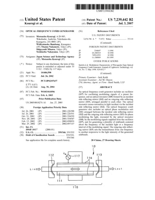


This document describes an optical frequency comb generator comprising: an oscillator that oscillates modulating signals of a preset frequency, an optical resonator formed by parallel reflecting mirrors to cause resonance of incident light, and an optical phase modulation unit between the mirrors to phase modulate the resonant light using the modulating signals. This generates sidebands around the incident light frequency at intervals of the modulating signal frequency. The outgoing mirror transmittance is responsive to the sideband light intensities.


